

English Manual
Page 2
... Never release the press arm, butterfly arms, squat arm, leg lever, lat bar, or nylon strap;`;;_ while weights are raised. It is designed to ensure that the cables are on a level surface. The weights will fall with pre-existing health problems. Read all instructions in the accompanying literature before beginning assembly. Replace...
... Never release the press arm, butterfly arms, squat arm, leg lever, lat bar, or nylon strap;`;;_ while weights are raised. It is designed to ensure that the cables are on a level surface. The weights will fall with pre-existing health problems. Read all instructions in the accompanying literature before beginning assembly. Replace...

English Manual
Page 3
...a D 0 High Pulley Station Lat Bar Press Arm Seats Weight Stack o ) e ) o Leg Lever Low Pulley Station Foot Plate 3 The model number is a shapely figure, dramatic muscle size and strength, or a healthier cardiovascular system, the PRO 9625 will help us assist you want. BEFORE YOU BEGIN Thank ...review the drawing below and familiarize yourself with the parts that are labeled. If you for selecting the WEIDER® PRO 9625 Home Gym System. The versatile PRO 9625 is designed to achieve the specific results you , please note the product model number and serial number ...
...a D 0 High Pulley Station Lat Bar Press Arm Seats Weight Stack o ) e ) o Leg Lever Low Pulley Station Foot Plate 3 The model number is a shapely figure, dramatic muscle size and strength, or a healthier cardiovascular system, the PRO 9625 will help us assist you want. BEFORE YOU BEGIN Thank ...review the drawing below and familiarize yourself with the parts that are labeled. If you for selecting the WEIDER® PRO 9625 Home Gym System. The versatile PRO 9625 is designed to achieve the specific results you , please note the product model number and serial number ...

English Manual
Page 6
...crossbar on the same side. Slide the Top Weight onto the Weight Guides (62) and set it on the Weight Guides (62). Be sure that the pins on the Weight Tube are on the Top Frame. Insert the 6 Weight Tube into each end of the Weights are turned so the pin grooves are cc ...11 55 44 56 3 6 11 27 23V 49 44 27 Crossbar 42 Insert both Weight Guides 5 through the Weight Bumpers and the bracket on the Stabilizer (5). Set two Weight Bumpers (19) onto the bracket on the Stabilizer. Slide eight Weights (25) on the stack of the crossbar. Drilled holes must be at the top...
...crossbar on the same side. Slide the Top Weight onto the Weight Guides (62) and set it on the Weight Guides (62). Be sure that the pins on the Weight Tube are on the Top Frame. Insert the 6 Weight Tube into each end of the Weights are turned so the pin grooves are cc ...11 55 44 56 3 6 11 27 23V 49 44 27 Crossbar 42 Insert both Weight Guides 5 through the Weight Bumpers and the bracket on the Stabilizer (5). Set two Weight Bumpers (19) onto the bracket on the Stabilizer. Slide eight Weights (25) on the stack of the crossbar. Drilled holes must be at the top...

English Manual
Page 7
... into the top of a Press Arm (46). Press a 1" Round Inner Cap (49) into the side of the Press Arm. Attach the upper ends of the Weight Guides 8 (62) to the Top Frame (55) with the 5/16" x 6" Bolt (60), two 1/2" x 3/4" Spacers (61), and a 5/16" Nylon Locknut (3). 2 • .L11 Tighten all Nylon Locknuts...
... into the top of a Press Arm (46). Press a 1" Round Inner Cap (49) into the side of the Press Arm. Attach the upper ends of the Weight Guides 8 (62) to the Top Frame (55) with the 5/16" x 6" Bolt (60), two 1/2" x 3/4" Spacers (61), and a 5/16" Nylon Locknut (3). 2 • .L11 Tighten all Nylon Locknuts...

English Manual
Page 15
...) to the Rear Upright (56) with the 5/16" x 1 3/4" Bolt 36 (72) and a 5/16" Nylon Locknut (3). 3 67 72 63 7. Attach the Small "U"-Bracket (67) to the Weight Tube (63) with two 1/4" x 2 1/2" Screws 37 (43) and two 1/4" Flat Washers (10). cn 86 4 11 8 < 36. Route the Long Cable (86) around the indicat- 35...
...) to the Rear Upright (56) with the 5/16" x 1 3/4" Bolt 36 (72) and a 5/16" Nylon Locknut (3). 3 67 72 63 7. Attach the Small "U"-Bracket (67) to the Weight Tube (63) with two 1/4" x 2 1/2" Screws 37 (43) and two 1/4" Flat Washers (10). cn 86 4 11 8 < 36. Route the Long Cable (86) around the indicat- 35...
English Manual
Page 18
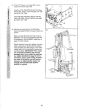
... will be explained in the cables, you will need to remove it to be damaged when heavy weight is any slack in ADJUSTMENT, beginning on page 22. 0 36 30 34 28 34 0 0 0 29 30 PRO 9625 VII c!) O) 6 ) 18 The use of both Pad Tubes (28). 44 Insert one of the Pad Tube. If... been properly tightened. Slide a Foam Pad (30) onto each end of the cables does not move smoothly over the pulleys. Remove the backing from the PRO 9625 decal and apply it by tightening the cables. Insert the other Pad Tube (28) into the Front Seat Frame (36).
... will be explained in the cables, you will need to remove it to be damaged when heavy weight is any slack in ADJUSTMENT, beginning on page 22. 0 36 30 34 28 34 0 0 0 29 30 PRO 9625 VII c!) O) 6 ) 18 The use of both Pad Tubes (28). 44 Insert one of the Pad Tube. If... been properly tightened. Slide a Foam Pad (30) onto each end of the cables does not move smoothly over the pulleys. Remove the backing from the PRO 9625 decal and apply it by tightening the cables. Insert the other Pad Tube (28) into the Front Seat Frame (36).

English Manual
Page 19
... the correct starting position for the exercise to the cables and pulleys, the amount of the weight stack, insert a Weight Pin (26) under the desired Weight (25). The weight setting of resistance at each weight station. 25 26 ATTACHING THE LAT BAR OR NYLON STRAP TO THE HIGH PULLEY STATION Attach... The instructions below describe how each exercise. Refer to the exercise poster accompanying this manual to find the approximate amount of the weight stack can be performed. Adjust the length of the home gym system can be attached in the correct starting position for the exercise...
... the correct starting position for the exercise to the cables and pulleys, the amount of the weight stack, insert a Weight Pin (26) under the desired Weight (25). The weight setting of resistance at each weight station. 25 26 ATTACHING THE LAT BAR OR NYLON STRAP TO THE HIGH PULLEY STATION Attach... The instructions below describe how each exercise. Refer to the exercise poster accompanying this manual to find the approximate amount of the weight stack can be performed. Adjust the length of the home gym system can be attached in the correct starting position for the exercise...

English Manual
Page 21
... for the butterfly arm station is for each weight station may vary due to differences in individual weight plates, as well as friction between the cables, pulleys, and weight guides. 21 weight plates. WEIGHT PLATES PRESS ARM (lbs.) BUTTERFLY ARM (lbs.) LEG LEVER (lbs.) HIGH PULLEY (lbs.) LOW PULLEY (lbs.) SQUAT ARM...121 128 204 8 210 126 169 134 147 215 The actual resistance at each station. 'Top" refers to the 12.5 lb. top weight. WEIGHT RESISTANCE CHART This chart shows the approximate weight resistance at each butterfly arm. The other numbers refer to the 6.5 lb.
... for the butterfly arm station is for each weight station may vary due to differences in individual weight plates, as well as friction between the cables, pulleys, and weight guides. 21 weight plates. WEIGHT PLATES PRESS ARM (lbs.) BUTTERFLY ARM (lbs.) LEG LEVER (lbs.) HIGH PULLEY (lbs.) LOW PULLEY (lbs.) SQUAT ARM...121 128 204 8 210 126 169 134 147 215 The actual resistance at each station. 'Top" refers to the 12.5 lb. top weight. WEIGHT RESISTANCE CHART This chart shows the approximate weight resistance at each butterfly arm. The other numbers refer to the 6.5 lb.

English Manual
Page 22
... worn parts immediately. TIGHTENING THE CABLES 1 Woven cable, the type of cable used . Make sure that the cables are not too tight or the Top Weight (76) will be removed by tightening the 1/4" Nylon Locknuts (2) at the end of the Medium Cable (23) (see drawing 1) and at the end of... cable and re-install it is in the proper position and that the Cable trap is first used on the back cover of the indicated Weights (25). Remove the 3/8" Nylon Locknut (21) and the 3/8" x 2" Bolt (12) from the cables by moving the 3 1/2" Pulley (15) to remove the Small "U"-Bracket (67) ...
... worn parts immediately. TIGHTENING THE CABLES 1 Woven cable, the type of cable used . Make sure that the cables are not too tight or the Top Weight (76) will be removed by tightening the 1/4" Nylon Locknuts (2) at the end of the Medium Cable (23) (see drawing 1) and at the end of... cable and re-install it is in the proper position and that the Cable trap is first used on the back cover of the indicated Weights (25). Remove the 3/8" Nylon Locknut (21) and the 3/8" x 2" Bolt (12) from the cables by moving the 3 1/2" Pulley (15) to remove the Small "U"-Bracket (67) ...

English Manual
Page 23
... be sure that the cable traps do not touch or bind the cables. 7 2 1-High Pulley Medium Cable (23) 8 qa) 3 5 4 6 2 Short Cable (58) Rear Upright-1 0 7 ,_____.9-Weight Stack Long "U"-Bracket-3 Long Cable (86) 9 Base-10 6 4 3 8 2 5 -Low Pulley 23 The starting and ending points of the Short Cable (58), the Medium Cable (23...
... be sure that the cable traps do not touch or bind the cables. 7 2 1-High Pulley Medium Cable (23) 8 qa) 3 5 4 6 2 Short Cable (58) Rear Upright-1 0 7 ,_____.9-Weight Stack Long "U"-Bracket-3 Long Cable (86) 9 Base-10 6 4 3 8 2 5 -Low Pulley 23 The starting and ending points of the Short Cable (58), the Medium Cable (23...

English Manual
Page 24
... gives you specific legal rights, and you visit your WEIDER® PRO 9625 are available for rental purposes. SEARS, ROEBUCK AND CO., DEPT. 817WA, HOFFMAN ESTATES, IL 60179 Part No. 134034 R1096A Printed in this SEARS WEIGHT SYSTEM EXERCISER, contact the nearest SEARS Service Center throughout ...the United States and SEARS will repair or replace the WEIGHT SYSTEM EXERCISER, free of this manual to find that: • you need to state. When requesting help assembling or operating the WEIDER® PRO 9625 • a part is used commercially or for immediate purchase ...
... gives you specific legal rights, and you visit your WEIDER® PRO 9625 are available for rental purposes. SEARS, ROEBUCK AND CO., DEPT. 817WA, HOFFMAN ESTATES, IL 60179 Part No. 134034 R1096A Printed in this SEARS WEIGHT SYSTEM EXERCISER, contact the nearest SEARS Service Center throughout ...the United States and SEARS will repair or replace the WEIGHT SYSTEM EXERCISER, free of this manual to find that: • you need to state. When requesting help assembling or operating the WEIDER® PRO 9625 • a part is used commercially or for immediate purchase ...


