
English Manual
Page 1
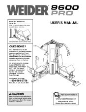
.... Serial Number Decal (Under Seat) QUESTIONS? If you have questions, or if there are committed to providing complete customer satisfaction. USER'S MANUAL Visit our website at www.weiderfitness.com new products, prizes, fitness tips, and much more! TO AVOID DELAYS, PLEASE CALL DIRECT TO OUR TOLL-FREE CUSTOMER HOT LINE. MST CAUTION Read all precautions and instructions in the space...
.... Serial Number Decal (Under Seat) QUESTIONS? If you have questions, or if there are committed to providing complete customer satisfaction. USER'S MANUAL Visit our website at www.weiderfitness.com new products, prizes, fitness tips, and much more! TO AVOID DELAYS, PLEASE CALL DIRECT TO OUR TOLL-FREE CUSTOMER HOT LINE. MST CAUTION Read all precautions and instructions in the space...
English Manual
Page 2
..., or products used as store display models. TABLE OF CONTENTS LIMITED WARRANTY 2 IMPORTANT PRECAUTIONS 3 BEFORE YOU BEGIN 4 ASSEMBLY 5 ADJUSTMENTS 21 WEIGHT RESISTANCE CHART 23 TROUBLESHOOTING AND MAINTENANCE 24 CABLE DIAGRAMS 25 ORDERING REPLACEMENT PARTS Back Cover Note: A PART IDENTIFICATION CHART and a PART LIST/EXPLODED DRAWING are attached in lieu of any product or damage to a product caused by or attributable to the original purchaser. WEIDER is authorized by an ICON authorized service center, products used for...
..., or products used as store display models. TABLE OF CONTENTS LIMITED WARRANTY 2 IMPORTANT PRECAUTIONS 3 BEFORE YOU BEGIN 4 ASSEMBLY 5 ADJUSTMENTS 21 WEIGHT RESISTANCE CHART 23 TROUBLESHOOTING AND MAINTENANCE 24 CABLE DIAGRAMS 25 ORDERING REPLACEMENT PARTS Back Cover Note: A PART IDENTIFICATION CHART and a PART LIST/EXPLODED DRAWING are attached in lieu of any product or damage to a product caused by or attributable to the original purchaser. WEIDER is authorized by an ICON authorized service center, products used for...
English Manual
Page 3
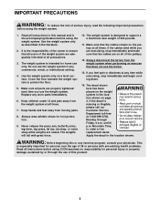
... moving parts. 8. If the decal is intended for foot protection. 9. This is designed to order a free replacement decal. Always wear athletic shoes for home use the lat bar. 13. Replace any commercial, rental, or institutional setting. 4. Use the weight system only on the pulleys at 1-800-999-3756, Monday through the use of this or any time while exercising, stop immediately and make sure that all users...
... moving parts. 8. If the decal is intended for foot protection. 9. This is designed to order a free replacement decal. Always wear athletic shoes for home use the lat bar. 13. Replace any commercial, rental, or institutional setting. 4. Use the weight system only on the pulleys at 1-800-999-3756, Monday through the use of this or any time while exercising, stop immediately and make sure that all users...
English Manual
Page 4
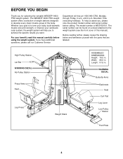
... model number is to achieve the specific results you for selecting the versatile WEIDER® 9600 PRO weight system. High Pulley Station Lat Bar WARNING DECAL Ab Pulley Station Press Arms Seat Leg Press Weight Stack ASSEMBLED DIMENSIONS: Height: 76.0 in . Mountain Time (excluding holidays). Before reading further, please review the drawing below and familiarize yourself with the parts that are labeled. To help you to tone your body, build dramatic muscle size...
... model number is to achieve the specific results you for selecting the versatile WEIDER® 9600 PRO weight system. High Pulley Station Lat Bar WARNING DECAL Ab Pulley Station Press Arms Seat Leg Press Weight Stack ASSEMBLED DIMENSIONS: Height: 76.0 in . Mountain Time (excluding holidays). Before reading further, please review the drawing below and familiarize yourself with the parts that are labeled. To help you to tone your body, build dramatic muscle size...
English Manual
Page 5
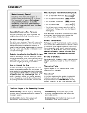
... and use it . Note: Assembly will attach the cables and pulleys that connect the arms to make sure that the weight system can be used in a cleared area and remove the packing materials. How to do otherwise. Cable Assembly-During this manual is completed. ASSEMBLY Make Assembly Easier! Everything in the location where it . Before beginning assembly, make assembly as easy as you assemble them, unless instructed to Identify Parts To...
... and use it . Note: Assembly will attach the cables and pulleys that connect the arms to make sure that the weight system can be used in a cleared area and remove the packing materials. How to do otherwise. Cable Assembly-During this manual is completed. ASSEMBLY Make Assembly Easier! Everything in the location where it . Before beginning assembly, make assembly as easy as you assemble them, unless instructed to Identify Parts To...
English Manual
Page 6
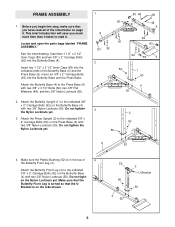
... Butterfly Base (4) with two 3/8" Nylon Locknuts (50). Do not tighten 3 the Nylon Locknuts yet. 2 3. Attach the Butterfly Front Leg (3) to the Press Base (6) with two 3/8" Nylon Locknuts (50). Do not tighten the Nylon Locknuts yet. Locate and open the parts bags labeled "FRAME ASSEMBLY." FRAME ASSEMBLY 1 1. Attach the Press Upright (2) to the indicated 3/8" x 2" Carriage Bolts (92) on the side shown. 52 50 4 92 3 U-Bracket...
... Butterfly Base (4) with two 3/8" Nylon Locknuts (50). Do not tighten 3 the Nylon Locknuts yet. 2 3. Attach the Butterfly Front Leg (3) to the Press Base (6) with two 3/8" Nylon Locknuts (50). Do not tighten the Nylon Locknuts yet. Locate and open the parts bags labeled "FRAME ASSEMBLY." FRAME ASSEMBLY 1 1. Attach the Press Upright (2) to the indicated 3/8" x 2" Carriage Bolts (92) on the side shown. 52 50 4 92 3 U-Bracket...
English Manual
Page 10
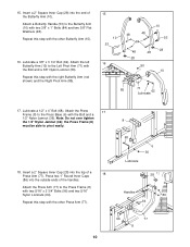
...tighten the 1/2" Nylon Jamnut (36); Attach the Press Arm (77) to the Left Pivot Arm (71) with the Bolt and a 3/8" Nylon Locknut (50). Attach the left Butterfly Arm (10) to the Press Frame (8) with the Bolt and a 1/2" Nylon Jamnut (36). the Press Frame (8) must be able to the Press Base (6) with two 5/16" x 2 3/4" Bolts... ends of a 18 Press Arm (77). Repeat this step with two 3/8" x 1" Bolts (84) and two 3/8" Flat Washers (48). Attach the Press 17 Frame (8) to pivot easily. 18. Repeat this step with the other Press Arm (77). 8 68 6 36 Lubricate 28 Handles 86 64 ...
...tighten the 1/2" Nylon Jamnut (36); Attach the Press Arm (77) to the Left Pivot Arm (71) with the Bolt and a 3/8" Nylon Locknut (50). Attach the left Butterfly Arm (10) to the Press Frame (8) with the Bolt and a 1/2" Nylon Jamnut (36). the Press Frame (8) must be able to the Press Base (6) with two 5/16" x 2 3/4" Bolts... ends of a 18 Press Arm (77). Repeat this step with two 3/8" x 1" Bolts (84) and two 3/8" Flat Washers (48). Attach the Press 17 Frame (8) to pivot easily. 18. Repeat this step with the other Press Arm (77). 8 68 6 36 Lubricate 28 Handles 86 64 ...
English Manual
Page 11
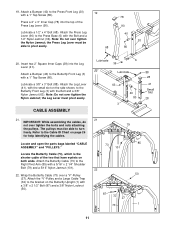
... Leg (3) with a 1" Tap Screw (80). Note: Do not over tighten the Nylon Jamnut; Locate and open the parts bags labeled "CABLE ASSEMBLY" and "PULLEYS." Attach the "V"-Pulley and a Large Cable Trap (32) to the bracket on the side shown, to the Cable ID Chart on both ends. the Press Leg Lever must pivot easily. the Leg Lever must be able to the Press Front Leg (20) 19 with the Bolt...
... Leg (3) with a 1" Tap Screw (80). Note: Do not over tighten the Nylon Jamnut; Locate and open the parts bags labeled "CABLE ASSEMBLY" and "PULLEYS." Attach the "V"-Pulley and a Large Cable Trap (32) to the bracket on the side shown, to the Cable ID Chart on both ends. the Press Leg Lever must pivot easily. the Leg Lever must be able to the Press Front Leg (20) 19 with the Bolt...
English Manual
Page 12
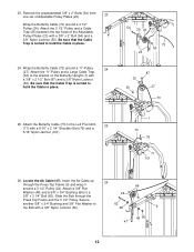
... 73 25. Slide the Bolt through the Press Top Frame (9) and wrap it 66 around a 3 1/2" Pulley (24). 23. Be sure that the Cable Trap is turned to the bracket on the Butterfly Upright (1) with a 3/8" Nylon Locknut (50). 48 9 48 50 47 12 Locate the Ab Cable (47). Remove the preassembled 3/8" x 2" Bolts (54) from one set of the Adjustable Pulley Plates (23) with a 5/16...
... 73 25. Slide the Bolt through the Press Top Frame (9) and wrap it 66 around a 3 1/2" Pulley (24). 23. Be sure that the Cable Trap is turned to the bracket on the Butterfly Upright (1) with a 3/8" Nylon Locknut (50). 48 9 48 50 47 12 Locate the Ab Cable (47). Remove the preassembled 3/8" x 2" Bolts (54) from one set of the Adjustable Pulley Plates (23) with a 5/16...
English Manual
Page 14
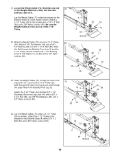
... Front Leg (3) and the 3 1/2" Pulley. Be sure the Weight Cable is in the manner shown. Attach the 3 1/2" Pulley to the Leg Lever (41) with a 3/8" x 2" Bolt (54) and a 3/8" Nylon Locknut (50). Note that one end 31 of the 3 1/2" Pulley. 3 24 54 4 72 50 Bracket 32. Secure another 5/8" x 3/4" Bushing and 3/8" Flat Washer to a 3/8" x 3 1/4" Bolt (62). Locate the Weight Cable (72). 31. Lay the Weight Cable (72) under a 3 1/2" Pulley...
... Front Leg (3) and the 3 1/2" Pulley. Be sure the Weight Cable is in the manner shown. Attach the 3 1/2" Pulley to the Leg Lever (41) with a 3/8" x 2" Bolt (54) and a 3/8" Nylon Locknut (50). Note that one end 31 of the 3 1/2" Pulley. 3 24 54 4 72 50 Bracket 32. Secure another 5/8" x 3/4" Bushing and 3/8" Flat Washer to a 3/8" x 3 1/4" Bolt (62). Locate the Weight Cable (72). 31. Lay the Weight Cable (72) under a 3 1/2" Pulley...
English Manual
Page 17
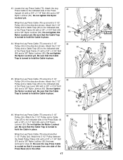
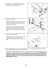
... not tighten the Nylon Locknut yet. Attach the 3 1/2" Pulley and a Cable Trap (25) to hold the Cable in the direction shown. Be sure that it crosses from one side of the Press Seat Frame (7) with a 3/8" x 5 1/2" Bolt (55) and a 3/8" Nylon Locknut (50). Wrap the Leg Press Cable (75) around a 3 1/2" 46 Pulley (24). Be sure that the Cable 60 24 Trap is routed so that the Cable Trap is turned...
... not tighten the Nylon Locknut yet. Attach the 3 1/2" Pulley and a Cable Trap (25) to hold the Cable in the direction shown. Be sure that it crosses from one side of the Press Seat Frame (7) with a 3/8" x 5 1/2" Bolt (55) and a 3/8" Nylon Locknut (50). Wrap the Leg Press Cable (75) around a 3 1/2" 46 Pulley (24). Be sure that the Cable 60 24 Trap is routed so that the Cable Trap is turned...
English Manual
Page 19
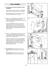
... (44) into the Press Upright and snap the Adjustment Knob into the end of the Butterfly Backrest Frame (70). See drawing A. SEAT ASSEMBLY 51 51. Locate and open the parts bag labeled "SEAT ASSEMBLY." Attach the Shroud (34) to the Butterfly Backrest Frame with four 1/4" x 3/4" Bolts (49). Attach a Seat (13) to the Press Backrest Frame with four 1/4" x 3/4" Bolts (49). 35 49 Pull out the Adjustment Knob (5) on the Butterfly...
... (44) into the Press Upright and snap the Adjustment Knob into the end of the Butterfly Backrest Frame (70). See drawing A. SEAT ASSEMBLY 51 51. Locate and open the parts bag labeled "SEAT ASSEMBLY." Attach the Shroud (34) to the Butterfly Backrest Frame with four 1/4" x 3/4" Bolts (49). Attach a Seat (13) to the Press Backrest Frame with four 1/4" x 3/4" Bolts (49). 35 49 Pull out the Adjustment Knob (5) on the Butterfly...
English Manual
Page 20
...). The use of this manual for proper cable routing. Attach the Curl Pad (91) to the Press Leg Lever (90) with four 1/4" x 3/4" Bolts (49). IMPORTANT: If the cables are not properly installed, they may be sure that all parts have been properly tightened. See TROUBLESHOOTING AND MAINTENANCE on page 21 of the remaining parts will need to remove the slack by inserting the Large Adjustment Knob (46) and turning it...
...). The use of this manual for proper cable routing. Attach the Curl Pad (91) to the Press Leg Lever (90) with four 1/4" x 3/4" Bolts (49). IMPORTANT: If the cables are not properly installed, they may be sure that all parts have been properly tightened. See TROUBLESHOOTING AND MAINTENANCE on page 21 of the remaining parts will need to remove the slack by inserting the Large Adjustment Knob (46) and turning it...
English Manual
Page 21
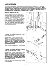
... THE HIGH PULLEY STATION Attach the Lat Bar (61) to the Ab Cable (47) with two Cable Clips. The Ab Strap (81) can be changed from the weight setting. CHANGING THE WEIGHT SETTING To change the weight setting of the weight stack, insert the Weight Pin (19) under the desired Weight (21) until the bent end of the Weight Pin is in 10 pound increments. Turn the bent end downward. Use the WEIGHT RESISTANCE CHART on page...
... THE HIGH PULLEY STATION Attach the Lat Bar (61) to the Ab Cable (47) with two Cable Clips. The Ab Strap (81) can be changed from the weight setting. CHANGING THE WEIGHT SETTING To change the weight setting of the weight stack, insert the Weight Pin (19) under the desired Weight (21) until the bent end of the Weight Pin is in 10 pound increments. Turn the bent end downward. Use the WEIGHT RESISTANCE CHART on page...
English Manual
Page 22
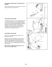
... To adjust a Backrest (12), loosen the Adjustment Knob (5) on the Press Upright (2) or the Butterfly Upright (not shown) by turning the Adjustment Knob clockwise until tight. ATTACHING THE AB STRAP TO THE AB PULLEY STATION Attach the Ab Strap (81) to the desired position, and snap the Adjustment Knob into a hole in the Backrest Frame (not shown). ADJUSTING THE CURL PAD Remove the Large Adjustment Knob (46) from the weight system...
... To adjust a Backrest (12), loosen the Adjustment Knob (5) on the Press Upright (2) or the Butterfly Upright (not shown) by turning the Adjustment Knob clockwise until tight. ATTACHING THE AB STRAP TO THE AB PULLEY STATION Attach the Ab Strap (81) to the desired position, and snap the Adjustment Knob into a hole in the Backrest Frame (not shown). ADJUSTING THE CURL PAD Remove the Large Adjustment Knob (46) from the weight system...
English Manual
Page 23
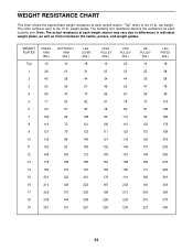
...arm resistance listed is the resistance for each weight station. Note: The actual resistance at each butterfly arm. weight plates. "Top" refers to differences in individual weight plates, as well as friction between the cables, pulleys, and weight guides. WEIGHT RESISTANCE CHART This chart shows the approximate weight resistance at each weight station may vary due to the 10 lb. top weight. The other numbers refer to the 10 lb. WEIGHT... 180 191 202 213 225 236 AB PULLEY (lbs.) 14 25 36 47 59 70 81 92 103 115 126 137 148 159 171 182 193 204 215 227 LEG PRESS (lbs.) 18 38 58 78 98 ...
...arm resistance listed is the resistance for each weight station. Note: The actual resistance at each butterfly arm. weight plates. "Top" refers to differences in individual weight plates, as well as friction between the cables, pulleys, and weight guides. WEIGHT RESISTANCE CHART This chart shows the approximate weight resistance at each weight station may vary due to the 10 lb. top weight. The other numbers refer to the 10 lb. WEIGHT... 180 191 202 213 225 236 AB PULLEY (lbs.) 14 25 36 47 59 70 81 92 103 115 126 137 148 159 171 182 193 204 215 227 LEG PRESS (lbs.) 18 38 58 78 98 ...
English Manual
Page 24
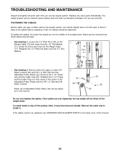
... the cables are over tighten the cables. If a cable tends to slip off the weight stack. If the cables need to the center of cable used . Loosen the 1/2" Plain Nut (100) on the back cover of the weight stack. The weight system can stretch slightly when it . TIGHTENING THE CABLES Woven cable, the type of the Adjustable Pulley Plates with the 3/8" x 2" Bolt and 3/8" Nylon Locknut. Screw the bolt a few turns into the...
... the cables are over tighten the cables. If a cable tends to slip off the weight stack. If the cables need to the center of cable used . Loosen the 1/2" Plain Nut (100) on the back cover of the weight stack. The weight system can stretch slightly when it . TIGHTENING THE CABLES Woven cable, the type of the Adjustable Pulley Plates with the 3/8" x 2" Bolt and 3/8" Nylon Locknut. Screw the bolt a few turns into the...

English Manual
Page 25
... Pulley 3 6 9 10 11-Press Upright 7 5 3 2 1-Press Upright Butterfly Cable (73) 4 5-Left Arm 2 3 1-Right Arm 25 The starting and ending points of the Leg Press Cable (75), the Ab Cable (47), the Butterfly Cable (73), and the Weight Cable (72). CABLE DIAGRAMS The cable diagrams on this page and the next page show the proper route for each Cable have not been correctly routed, the weight system will not function properly and damage may occur. Use...
... Pulley 3 6 9 10 11-Press Upright 7 5 3 2 1-Press Upright Butterfly Cable (73) 4 5-Left Arm 2 3 1-Right Arm 25 The starting and ending points of the Leg Press Cable (75), the Ab Cable (47), the Butterfly Cable (73), and the Weight Cable (72). CABLE DIAGRAMS The cable diagrams on this page and the next page show the proper route for each Cable have not been correctly routed, the weight system will not function properly and damage may occur. Use...
English Manual
Page 28
...; 2002 ICON Health & Fitness, Inc. The SERIAL NUMBER of the product (see the PART LIST and EXPLODED DRAWING attached at 1-800-999-3756, Monday through Friday, 6 a.m. Mountain Time (excluding holidays). The MODEL NUMBER of the product (WEIDER® 9600 PRO weight system) 3. To help us assist you, please be prepared to give the following information: 1. The KEY NUMBER and DESCRIPTION of the part(s) (see the front cover of this manual...
...; 2002 ICON Health & Fitness, Inc. The SERIAL NUMBER of the product (see the PART LIST and EXPLODED DRAWING attached at 1-800-999-3756, Monday through Friday, 6 a.m. Mountain Time (excluding holidays). The MODEL NUMBER of the product (WEIDER® 9600 PRO weight system) 3. To help us assist you, please be prepared to give the following information: 1. The KEY NUMBER and DESCRIPTION of the part(s) (see the front cover of this manual...
English Manual
Page 34
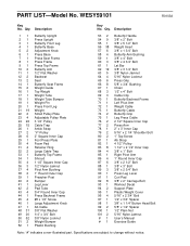
... Frame Left Pivot Arm Weight Cable Butterfly Cable Butterfly Grip Leg Press Cable 2 1/2" Square Inner Cap Press Arm 2" x 3" Inner Cap 5/16" x 2 1/4" Shoulder Bolt 1" Tap Screw Ab Strap 4 1/2" Pulley 1 1/2" x 2 1/2" Inner Cap 3/8" x 1" Bolt Right Pivot Arm 1" Round Inner Cap 3/8" x 2 1/2" Bolt 3/8" x 3" Bolt 3/8" x 2 3/4" Bolt Press Leg Lever Curl Pad 3/8" x 2" Carriage Bolt Workout Decal Support Plate Plastic Weight Cover 5/16" x 2 3/4" Bolt 1/2" x 3/4" Spacer 3/8" x 1 1/4" Button Head Bolt 5/8" x 1/2" Spacer 1/2" Plain Nut 5/16" Nylon Jamnut User's Manual Exercise Guide Note: "#" indicates...
... Frame Left Pivot Arm Weight Cable Butterfly Cable Butterfly Grip Leg Press Cable 2 1/2" Square Inner Cap Press Arm 2" x 3" Inner Cap 5/16" x 2 1/4" Shoulder Bolt 1" Tap Screw Ab Strap 4 1/2" Pulley 1 1/2" x 2 1/2" Inner Cap 3/8" x 1" Bolt Right Pivot Arm 1" Round Inner Cap 3/8" x 2 1/2" Bolt 3/8" x 3" Bolt 3/8" x 2 3/4" Bolt Press Leg Lever Curl Pad 3/8" x 2" Carriage Bolt Workout Decal Support Plate Plastic Weight Cover 5/16" x 2 3/4" Bolt 1/2" x 3/4" Spacer 3/8" x 1 1/4" Button Head Bolt 5/8" x 1/2" Spacer 1/2" Plain Nut 5/16" Nylon Jamnut User's Manual Exercise Guide Note: "#" indicates...


