

English Manual
Page 1
... CALL DIRECT TO OUR TOLL-FREE CUSTOMER HOT UNE.The trained technicians on our customer hot line will guarantee you . PRC9515 Model No. As a manufactu-iii;we will provide immediate assistance, free of charge to providing complete customer satisfaction. CUSTOMER HOT LINE: 1-800-225-0653 Mon.-Fri., 6 a.m.-6 p.m. MST USER'S MANUAL OO OO ii I -/ I, ',!I-I;ItIioI am"Imlammloimfi i.,4- WESY95150 Serial...
... CALL DIRECT TO OUR TOLL-FREE CUSTOMER HOT UNE.The trained technicians on our customer hot line will guarantee you . PRC9515 Model No. As a manufactu-iii;we will provide immediate assistance, free of charge to providing complete customer satisfaction. CUSTOMER HOT LINE: 1-800-225-0653 Mon.-Fri., 6 a.m.-6 p.m. MST USER'S MANUAL OO OO ii I -/ I, ',!I-I;ItIioI am"Imlammloimfi i.,4- WESY95150 Serial...

English Manual
Page 2
... that specifically set forth herein. Accordingly, the above is authorized by an ICON authorized service center, to products used as store display models. Some states do not allow limitations on how long an implied warranty lasts. TABLE OF CONTENTS LIMITED WARRANTY IMPORTANT PRECAUTIONS BEFORE YOU BEGIN ASSEMBLY ADJUSTMENT WEIGHT RESISTANCE CHART TROUBLE-SHOOTING AND MAINTENANCE CABLE DIAGRAM PART LIST EXPLODED DRAWING ORDERING REPLACEMENT PARTS 2 3 4 5 17 19 20 21 22 23 Back Cover Note: A PART IDENTIFICATION CHART is attached...
... that specifically set forth herein. Accordingly, the above is authorized by an ICON authorized service center, to products used as store display models. Some states do not allow limitations on how long an implied warranty lasts. TABLE OF CONTENTS LIMITED WARRANTY IMPORTANT PRECAUTIONS BEFORE YOU BEGIN ASSEMBLY ADJUSTMENT WEIGHT RESISTANCE CHART TROUBLE-SHOOTING AND MAINTENANCE CABLE DIAGRAM PART LIST EXPLODED DRAWING ORDERING REPLACEMENT PARTS 2 3 4 5 17 19 20 21 22 23 Back Cover Note: A PART IDENTIFICATION CHART is attached...

English Manual
Page 4
... the specific results you , please note the product model number and serial number before Before reading further, please review the drawing using the WEIDER• PRO 9515 Home Gym System. below and familiarize yourself with the parts that are If you for selecting the WEIDER® PRO 9515 Home Gym System. Length: 53 in. The versatile PRO 9515 offers a selection of weight stations designed to the PRO 9515 (see the front cover of the body.
... the specific results you , please note the product model number and serial number before Before reading further, please review the drawing using the WEIDER• PRO 9515 Home Gym System. below and familiarize yourself with the parts that are If you for selecting the WEIDER® PRO 9515 Home Gym System. Length: 53 in. The versatile PRO 9515 offers a selection of weight stations designed to the PRO 9515 (see the front cover of the body.

English Manual
Page 5
...; As you begin each end of ratchet wrenches. 1. The high side of the PRO 9515 in the Stabilizer (5). Press a 2" Square Inner Cap (27) into four stages: 1) frame assembly, 2) press and butterfly arm assembly, 3) cable and pulley assembly, and 4) seat and backrest assembly. Slide the Rear Upright (56) onto the Carriage Bolts. Do not tighten the Nylon Locknuts yet. 5 High Side of the Base (4) onto the 5/16...
...; As you begin each end of ratchet wrenches. 1. The high side of the PRO 9515 in the Stabilizer (5). Press a 2" Square Inner Cap (27) into four stages: 1) frame assembly, 2) press and butterfly arm assembly, 3) cable and pulley assembly, and 4) seat and backrest assembly. Slide the Rear Upright (56) onto the Carriage Bolts. Do not tighten the Nylon Locknuts yet. 5 High Side of the Base (4) onto the 5/16...

English Manual
Page 6
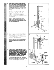
... 25 CD 63 Large Pin Groove 64 6 Press two Weight Bushings (78) into the Weight Cover (67) until the 3/8" Nut is on the Top Frame. Slide the Front Upright (42) onto the 5/16" x 2 2 1/2" Carriage Bolts (1). Hand-tighten a 5/16" Nylon Locknut (3) onto each end of the fourteen Weights (25) so the large pin groove is touching the Weight Cover. Thread the 3/8" Nut (77...
... 25 CD 63 Large Pin Groove 64 6 Press two Weight Bushings (78) into the Weight Cover (67) until the 3/8" Nut is on the Top Frame. Slide the Front Upright (42) onto the 5/16" x 2 2 1/2" Carriage Bolts (1). Hand-tighten a 5/16" Nylon Locknut (3) onto each end of the fourteen Weights (25) so the large pin groove is touching the Weight Cover. Thread the 3/8" Nut (77...
English Manual
Page 7
... fit.The Plastic Bushings should fit onto each welded spacer on the Press Frame (17). 7 Slide the Press Frame into the bracket on the same side. 67 Slide the Weight Cover (67) and the top weight (inside the Weight Cover) onto the Weight Guides (62). Attach the Press Frame (17) to the Top Frame (55) with the 3/8" x 8" Bolt and a 3/8" Nylon Locknut (21). 4 -Tube 7 Pulleys 17 Lubricate...
... fit.The Plastic Bushings should fit onto each welded spacer on the Press Frame (17). 7 Slide the Press Frame into the bracket on the same side. 67 Slide the Weight Cover (67) and the top weight (inside the Weight Cover) onto the Weight Guides (62). Attach the Press Frame (17) to the Top Frame (55) with the 3/8" x 8" Bolt and a 3/8" Nylon Locknut (21). 4 -Tube 7 Pulleys 17 Lubricate...

English Manual
Page 8
Note: The "V"-Pulleys (6), Long Cable Traps (50), 3/8" x 2 1/2" Bolts (7), and 3/8" Nylon Locknuts (21) are shown disassembled for step 10. 50 7 50 6 6. Press a 1" Round Inner Cap (49) into the 8 top of a Press Arm (46). They are pre-attached. Welded Brackets 47 • 21 48 10. Tap two 1" Retainers (69) and a 1" Round Cover Cap (70) onto the right axle. Attach the Left Arm (47) in the...
Note: The "V"-Pulleys (6), Long Cable Traps (50), 3/8" x 2 1/2" Bolts (7), and 3/8" Nylon Locknuts (21) are shown disassembled for step 10. 50 7 50 6 6. Press a 1" Round Inner Cap (49) into the 8 top of a Press Arm (46). They are pre-attached. Welded Brackets 47 • 21 48 10. Tap two 1" Retainers (69) and a 1" Round Cover Cap (70) onto the right axle. Attach the Left Arm (47) in the...

English Manual
Page 9
... this manual to the CABLE DIAGRAM on the Left Arm (47). Route the Long Cable around a "V"-Pulley (6). E ASSEMBLY 11. During steps 11 through 25, refer to verify proper cable routing. Tighten the 3/8" x 3 3/4" Bolt (71) and the 3/8" Nylon Locknut (not shown). 13. Attach the "V"-Pulley and a Long Cable 13 Trap (50) to hold the Cable in the groove of the Cable with a 3/8" x 2 1/2" Bolt (7) and a 3/8" Nylon Locknut (21). Route the Long Cable (23...
... this manual to the CABLE DIAGRAM on the Left Arm (47). Route the Long Cable around a "V"-Pulley (6). E ASSEMBLY 11. During steps 11 through 25, refer to verify proper cable routing. Tighten the 3/8" x 3 3/4" Bolt (71) and the 3/8" Nylon Locknut (not shown). 13. Attach the "V"-Pulley and a Long Cable 13 Trap (50) to hold the Cable in the groove of the Cable with a 3/8" x 2 1/2" Bolt (7) and a 3/8" Nylon Locknut (21). Route the Long Cable (23...

English Manual
Page 10
... part identification. z 7 21 ----. . 12 10 Be sure that the Cable and Pulley move smoothly. 17 23 15 66 12 21/ Ati 57 \ 23 . Tighten the 3/8" x 2" Bolt (12) and the 3/8" Nylon Locknut (21). Attach a 3 1/2" Pulley (15) and a Cable Trap (66) to the bracket on the Right Arm (48). Note: The pulley in the Long "U"-Bracket (57) with a 3/8" x 2" Bolt (12) and a 3/8" Nylon Locknut (21). Route...
... part identification. z 7 21 ----. . 12 10 Be sure that the Cable and Pulley move smoothly. 17 23 15 66 12 21/ Ati 57 \ 23 . Tighten the 3/8" x 2" Bolt (12) and the 3/8" Nylon Locknut (21). Attach a 3 1/2" Pulley (15) and a Cable Trap (66) to the bracket on the Right Arm (48). Note: The pulley in the Long "U"-Bracket (57) with a 3/8" x 2" Bolt (12) and a 3/8" Nylon Locknut (21). Route...

English Manual
Page 11
... side of several preattached parts. Tighten the 3/8" Nylon Locknut (21) and the 3/8" x 3 3/4" Bolt (not shown). • 21 58 17 15 Ball Crossbar 11 Do not remove the Bolt.The Bolt has been shown removed for shipping purposes. Route the Short Cable (58) under the 3 1/2" Pulley (15) 20 attached to complete the assembly of the Press Frame and that the 3/8" x 3 3/4" Bolt (71), the 3/8" Flat Washer...
... side of several preattached parts. Tighten the 3/8" Nylon Locknut (21) and the 3/8" x 3 3/4" Bolt (not shown). • 21 58 17 15 Ball Crossbar 11 Do not remove the Bolt.The Bolt has been shown removed for shipping purposes. Route the Short Cable (58) under the 3 1/2" Pulley (15) 20 attached to complete the assembly of the Press Frame and that the 3/8" x 3 3/4" Bolt (71), the 3/8" Flat Washer...

English Manual
Page 12
...Bolt (71). 22. Tighten the 3/8" Nylon Locknut (21) and the 3/8" x 3 1/2" Bolt (not shown). 42 15 71 66 58 Inset shows view from other side • 58 • 15 66 21 17 23. See the Inset drawing. Route the Short Cable (58) around the 3 1/2" Pulley (15) attached to the lower bole la the Front Upright (42). Route the Short Cable...the Cable Trap (66) is turned to hold the Cable in place and that the Cable is turned to hold the Cable in place and that the 42 . 15 Cable Is routed around the 3 1/2" 21 Pulley (15) attached to the upper hole in the Press Frame ...
...Bolt (71). 22. Tighten the 3/8" Nylon Locknut (21) and the 3/8" x 3 1/2" Bolt (not shown). 42 15 71 66 58 Inset shows view from other side • 58 • 15 66 21 17 23. See the Inset drawing. Route the Short Cable (58) around the 3 1/2" Pulley (15) attached to the lower bole la the Front Upright (42). Route the Short Cable...the Cable Trap (66) is turned to hold the Cable in place and that the Cable is turned to hold the Cable in place and that the 42 . 15 Cable Is routed around the 3 1/2" 21 Pulley (15) attached to the upper hole in the Press Frame ...

English Manual
Page 14
...turned so the thickest end Is at the bottom. 42 41 43 10 Thickest End 27. The Legiever must be able to move freely. .Insert the 5/16" x 2" Eyebolt (35) into the Leg Lever (29) from the direction shown. Attach the Backrest (41) to the Seat Frame (36) with two 1/4"x 2 1/2" Screws (43) and two 1/4" Rat Washers (10). Tighten...33 Lubricate 32 3 9 8 3 Attach the other end of the Seat (13) to the Front Upright 26 (42) with a 1/4" Flat Washer (10) and the 1/4" x 2" Screw (24). 28. 26. Press a 1 1/2" Square Inner Cap (32) into the Leg Lever (29). 28 Lubricate the 5/16" x 2 1/4" Bolt ...
...turned so the thickest end Is at the bottom. 42 41 43 10 Thickest End 27. The Legiever must be able to move freely. .Insert the 5/16" x 2" Eyebolt (35) into the Leg Lever (29) from the direction shown. Attach the Backrest (41) to the Seat Frame (36) with two 1/4"x 2 1/2" Screws (43) and two 1/4" Rat Washers (10). Tighten...33 Lubricate 32 3 9 8 3 Attach the other end of the Seat (13) to the Front Upright 26 (42) with a 1/4" Flat Washer (10) and the 1/4" x 2" Screw (24). 28. 26. Press a 1 1/2" Square Inner Cap (32) into the Leg Lever (29). 28 Lubricate the 5/16" x 2 1/4" Bolt ...

English Manual
Page 16
... properly tightened. IMPORTANT: If the cables are not properly Installed, they may be explained in theillustrationbelow. 31 HIGH PULLEY BUTTERFLY Pro 9515 LEG DEVELOPER 0 OO O O 0 BENCH PRESS LOW PULLEY 32. See the CABLE DIAGRAM on page 21 of the cables does not move smoothly over the pulleys. Make sure that the cables move smoothly, find and correct the problem. If one of this manual. 31. Use of this manual for proper cable routing. Remove...
... properly tightened. IMPORTANT: If the cables are not properly Installed, they may be explained in theillustrationbelow. 31 HIGH PULLEY BUTTERFLY Pro 9515 LEG DEVELOPER 0 OO O O 0 BENCH PRESS LOW PULLEY 32. See the CABLE DIAGRAM on page 21 of the cables does not move smoothly over the pulleys. Make sure that the cables move smoothly, find and correct the problem. If one of this manual. 31. Use of this manual for proper cable routing. Remove...
English Manual
Page 17
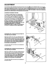
... ATTACHING THE LAT BAR OR NYLON STRAP TO THE LOW PULLEY STATION Attach the Lat Bar (54) to the Short Cable (58) with a Cable Clip (53). Adjust the length of the weight stack can be adjusted. The weight setting of the Chain between the Lat Bar and the Long Cable so the Lat Bar is in the correct starting position for the exercise to be performed. ADJUSTMENT The instructions below describe how each part of...
... ATTACHING THE LAT BAR OR NYLON STRAP TO THE LOW PULLEY STATION Attach the Lat Bar (54) to the Short Cable (58) with a Cable Clip (53). Adjust the length of the weight stack can be adjusted. The weight setting of the Chain between the Lat Bar and the Long Cable so the Lat Bar is in the correct starting position for the exercise to be performed. ADJUSTMENT The instructions below describe how each part of...

English Manual
Page 18
... Front Upright with the 5/16" x 2 3/4" Carriage Bolt (14) and the Seat Knob (40). First, be removed. Lift the Seat Frame off the Front Upright (42). Attach the Seat Frame to the Eyebolt (35) with a Cable Clip (53). ATTACHING AND REMOVING THE SEAT Set the bracket on the Seat Frame (36) onto the indicated pins on the Front Upright (42). For some exercises, the Seat (13) must be attached to the leg...
... Front Upright with the 5/16" x 2 3/4" Carriage Bolt (14) and the Seat Knob (40). First, be removed. Lift the Seat Frame off the Front Upright (42). Attach the Seat Frame to the Eyebolt (35) with a Cable Clip (53). ATTACHING AND REMOVING THE SEAT Set the bracket on the Seat Frame (36) onto the indicated pins on the Front Upright (42). For some exercises, the Seat (13) must be attached to the leg...

English Manual
Page 19
top weight. WEIGHT PLATES PRESS ARM (lbs.) BUTTERFLY ARM (lbs.) LEG LEVER HIGH PULLEY LOW PULLEY (lbs.) (lbs.) (lbs.) Top 12 1 40 2 62 4 107 5 6 146 7 162 8 190 9 205 10 220 11 243 12 263 13 272 14 295 7 21 13 21 ... 71 287 144 287 77 310 151 310 78 336 164 336 84 367 173 367 19 "Top" refers to the 10 lb. The other numbers refer to the 6 lb. The butterfly arm resistance listed is the resistance for each station. WEIGHT RESISTANCE CHART This chart shows the approximate weight resistance at each butterfly arm. weight plates.
top weight. WEIGHT PLATES PRESS ARM (lbs.) BUTTERFLY ARM (lbs.) LEG LEVER HIGH PULLEY LOW PULLEY (lbs.) (lbs.) (lbs.) Top 12 1 40 2 62 4 107 5 6 146 7 162 8 190 9 205 10 220 11 243 12 263 13 272 14 295 7 21 13 21 ... 71 287 144 287 77 310 151 310 78 336 164 336 84 367 173 367 19 "Top" refers to the 10 lb. The other numbers refer to the 6 lb. The butterfly arm resistance listed is the resistance for each station. WEIGHT RESISTANCE CHART This chart shows the approximate weight resistance at each butterfly arm. weight plates.

English Manual
Page 20
... 3/8" x 2" Bolt (12) from the Long "U"-Bracket (57). Remove the cable and re-Install It. Finger tighten the 3/8" Nut against the Weight Cover. 53 67 v 72 v 77 Slack can be tightened..Find the 3/8" x 4" Eyebolt (72) in the proper position and that the cables are not too tight. TROUBLE-SHOOTING AND MAINTENANCE Inspect and tighten all parts each time you may need to slip off the pulleys often...
... 3/8" x 2" Bolt (12) from the Long "U"-Bracket (57). Remove the cable and re-Install It. Finger tighten the 3/8" Nut against the Weight Cover. 53 67 v 72 v 77 Slack can be tightened..Find the 3/8" x 4" Eyebolt (72) in the proper position and that the cables are not too tight. TROUBLE-SHOOTING AND MAINTENANCE Inspect and tighten all parts each time you may need to slip off the pulleys often...

English Manual
Page 22
...Right Arm 1" Round Inner Cap Long Cable Trap 2" Square Outer Cap Chain Cable Clip Lat Bar Top Frame Rear Upright Long "U"-Bracket Short Cable - 3/8" x Bolt 5/16" x 6 1/2" Bolt 1/2" x 1" Spacer Weight Guide Weight Tube Weight Tube Bumper 1" Square Inner Cap Cable Trap Weight Cover 5/16" x Bolt 1" Retainer 1" Round Cover Cap 3/8" x 3 3/4" Bolt 3/8" x 4" Eyebolt 5/8" x 9/16" Spacer 1 1/4" x 2 1/2" Plastic Bushing 1" x 7/8" Plastic Bushing Top Weight 3/8" Nut Weight Bushing 3/8" x 1 1/2" Button Head Bolt User's Manual Exercise Poster Note: "#" indicates a non-illustrated part. PART.LIST Model...
...Right Arm 1" Round Inner Cap Long Cable Trap 2" Square Outer Cap Chain Cable Clip Lat Bar Top Frame Rear Upright Long "U"-Bracket Short Cable - 3/8" x Bolt 5/16" x 6 1/2" Bolt 1/2" x 1" Spacer Weight Guide Weight Tube Weight Tube Bumper 1" Square Inner Cap Cable Trap Weight Cover 5/16" x Bolt 1" Retainer 1" Round Cover Cap 3/8" x 3 3/4" Bolt 3/8" x 4" Eyebolt 5/8" x 9/16" Spacer 1 1/4" x 2 1/2" Plastic Bushing 1" x 7/8" Plastic Bushing Top Weight 3/8" Nut Weight Bushing 3/8" x 1 1/2" Button Head Bolt User's Manual Exercise Poster Note: "#" indicates a non-illustrated part. PART.LIST Model...

English Manual
Page 24
... © 1995 ICON Health & Fitness, Inc. ORDERING REPLACEMENT PARTS To order replacement parts, simply call our Customer Service Department toll-free at 1-800-225-0653, Monday through Friday, 6 a.m. until 6 p.m. To help us assist you, please be prepared to give the following information: • The MODEL NUMBER of the product (WESY95150). • The NAME of the product (WEIDER° 9515 Home Gym System). • The SERIAL NUMBER of the...
... © 1995 ICON Health & Fitness, Inc. ORDERING REPLACEMENT PARTS To order replacement parts, simply call our Customer Service Department toll-free at 1-800-225-0653, Monday through Friday, 6 a.m. until 6 p.m. To help us assist you, please be prepared to give the following information: • The MODEL NUMBER of the product (WESY95150). • The NAME of the product (WEIDER° 9515 Home Gym System). • The SERIAL NUMBER of the...

English Manual
Page 25
...:The assembly is provided to see if it has been pre-assembled. If you begin each assembly stage to the key number of the part. Important: Some parts may have been pre-assembled for assembly. REMOVE THIS PART IDENTIFICATION CHART FROM THE MANUAL This chart is divided into four stages: 1) frame assembly, 2) press and butterfly arm assembly, 3) cable and pulley assembly, and 4) seat and backrest assembly. The hardware for each part refers to open that parts...
...:The assembly is provided to see if it has been pre-assembled. If you begin each assembly stage to the key number of the part. Important: Some parts may have been pre-assembled for assembly. REMOVE THIS PART IDENTIFICATION CHART FROM THE MANUAL This chart is divided into four stages: 1) frame assembly, 2) press and butterfly arm assembly, 3) cable and pulley assembly, and 4) seat and backrest assembly. The hardware for each part refers to open that parts...


