
English Manual
Page 2
... PART LIST/EXPLODED DRAWING before beginning assembly. TABLE OF CONTENTS WARNING DECAL PLACEMENT 2 IMPORTANT PRECAUTIONS 3 BEFORE YOU BEGIN 4 ASSEMBLY 5 ADJUSTMENTS 24 WEIGHT RESISTANCE CHART 26 CABLE DIAGRAM 27 MAINTENANCE 29 EXERCISE GUIDELINES 30 ORDERING REPLACEMENT PARTS Back Cover FULL 90-DAY WARRANTY Back Cover Note: A PART IDENTIFICATION CHART and a PART LIST...
... PART LIST/EXPLODED DRAWING before beginning assembly. TABLE OF CONTENTS WARNING DECAL PLACEMENT 2 IMPORTANT PRECAUTIONS 3 BEFORE YOU BEGIN 4 ASSEMBLY 5 ADJUSTMENTS 24 WEIGHT RESISTANCE CHART 26 CABLE DIAGRAM 27 MAINTENANCE 29 EXERCISE GUIDELINES 30 ORDERING REPLACEMENT PARTS Back Cover FULL 90-DAY WARRANTY Back Cover Note: A PART IDENTIFICATION CHART and a PART LIST...
English Manual
Page 3
... the weight system. The weight system is designed to ensure that all users of the weight system are adequately informed of all times. Replace all cables at all precautions. 3. Always secure the weight stack with the lock pin and lock after exercising to protect the floor. 5. The weight system ... the weight system (see LOCKING THE WEIGHT STACK on page 25). 12. It is especially important for home use of 300 pounds. 8. If the cables bind as described in any exercise program, consult your physician. If you are on a level surface. Make sure all times. 10. Replace any time...
... the weight system. The weight system is designed to ensure that all users of the weight system are adequately informed of all times. Replace all cables at all precautions. 3. Always secure the weight stack with the lock pin and lock after exercising to protect the floor. 5. The weight system ... the weight system (see LOCKING THE WEIGHT STACK on page 25). 12. It is especially important for home use of 300 pounds. 8. If the cables bind as described in any exercise program, consult your physician. If you are on a level surface. Make sure all times. 10. Replace any time...
English Manual
Page 5
... the packing materials until you have divided the assembly process into four stages. How to make the task enjoyable, assembly will attach the cables and pulleys that the weight system can be assembled successfully by deciding to Unpack the Box To make sure to assemble the weight system... over a couple of another person. Do not dispose of time and by anyone. Cable Assembly-During this stage you assemble them, unless instructed to the weights. Assembly Requires Two Persons For your convenience and safety, assemble the weight...
... the packing materials until you have divided the assembly process into four stages. How to make the task enjoyable, assembly will attach the cables and pulleys that the weight system can be assembled successfully by deciding to Unpack the Box To make sure to assemble the weight system... over a couple of another person. Do not dispose of time and by anyone. Cable Assembly-During this stage you assemble them, unless instructed to the weights. Assembly Requires Two Persons For your convenience and safety, assemble the weight...
English Manual
Page 13
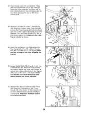
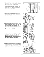
... Top Frame with an M10 x 80mm Bolt (111), two M10 Washers (116), two 19mm Spacers (77), and an M10 Nylon Locknut (114). 24. Cable Assembly 22. Route the Cable up through the Right Top Frame (7). Attach the Pulley inside the Top Frame with an M10 x 52mm Bolt (102) and an M10 Nylon... Locknut (114). Attach the Pulley, a Small Cable Trap (48), and two Half Finger Guards (42) at the second hole from the top of the two Pulley Plates (51) with an M10 x 80mm...
... Top Frame with an M10 x 80mm Bolt (111), two M10 Washers (116), two 19mm Spacers (77), and an M10 Nylon Locknut (114). 24. Cable Assembly 22. Route the Cable up through the Right Top Frame (7). Attach the Pulley inside the Top Frame with an M10 x 52mm Bolt (102) and an M10 Nylon... Locknut (114). Attach the Pulley, a Small Cable Trap (48), and two Half Finger Guards (42) at the second hole from the top of the two Pulley Plates (51) with an M10 x 80mm...
English Manual
Page 14
... "U"-bracket (52) with an M10 x 232mm Bolt (108), three M10 Washers (116), two 40mm Spacers (74), and an M10 Nylon Locknut (114). Locate the Ab Cable (72). Attach the Pulley and two Half Finger Guards (42) to the Dip Assist (21) with an M10 x 48mm Bolt (101) and an M10 Nylon...) to the Right Upright (4) with an M10 x 108mm Bolt (99), an M10 Washer (116), and an M10 Nylon Locknut (114). Wrap the Lat Cable (71) under a 90mm Pulley 31 (39). Make sure that the rod is inserted through the Left Top Frame (8). Make sure the Finger Guards are oriented ...
... "U"-bracket (52) with an M10 x 232mm Bolt (108), three M10 Washers (116), two 40mm Spacers (74), and an M10 Nylon Locknut (114). Locate the Ab Cable (72). Attach the Pulley and two Half Finger Guards (42) to the Dip Assist (21) with an M10 x 48mm Bolt (101) and an M10 Nylon...) to the Right Upright (4) with an M10 x 108mm Bolt (99), an M10 Washer (116), and an M10 Nylon Locknut (114). Wrap the Lat Cable (71) under a 90mm Pulley 31 (39). Make sure that the rod is inserted through the Left Top Frame (8). Make sure the Finger Guards are oriented ...
English Manual
Page 15
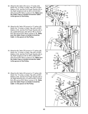
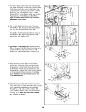
...) to the Right Butterfly Arm (17) with an M10 x 61mm Bolt (90) and an M10 Nylon Locknut (114). Wrap the Ab Cable (72) around a "V"-pulley (40). 34 Attach the "V"-pulley, a Cable Trap (49), an M10 Washer (116), and two Full Finger Guards (43) to the Right Upright (4) with an M10 x 61mm Bolt... (90) and an M10 Nylon Locknut (114). Make sure the Cable Trap is oriented to hold the Cable in the groove of the Pulley. 90 43 116 72 40 49 43 18 114 114 43 116 40 49 43 93...
...) to the Right Butterfly Arm (17) with an M10 x 61mm Bolt (90) and an M10 Nylon Locknut (114). Wrap the Ab Cable (72) around a "V"-pulley (40). 34 Attach the "V"-pulley, a Cable Trap (49), an M10 Washer (116), and two Full Finger Guards (43) to the Right Upright (4) with an M10 x 61mm Bolt... (90) and an M10 Nylon Locknut (114). Make sure the Cable Trap is oriented to hold the Cable in the groove of the Pulley. 90 43 116 72 40 49 43 18 114 114 43 116 40 49 43 93...
English Manual
Page 16
... are oriented as shown. 16 114 42 4 70 39 101 1 42 114 42 52 42 101 39 70 Make sure the flat edge of the Cable is over the rod in the Seat Frame. 116 75 Attach a 90mm Pulley (39) inside the Right Seat 38 Frame (9), over the Leg Lever... Cable (70), with the Bolt and an M8 Nylon Locknut (115). Attach a 90mm Pulley (39) inside the Leg Lever (11), over a 90mm 40 Pulley (39). 36. ...
... are oriented as shown. 16 114 42 4 70 39 101 1 42 114 42 52 42 101 39 70 Make sure the flat edge of the Cable is over the rod in the Seat Frame. 116 75 Attach a 90mm Pulley (39) inside the Right Seat 38 Frame (9), over the Leg Lever... Cable (70), with the Bolt and an M8 Nylon Locknut (115). Attach a 90mm Pulley (39) inside the Leg Lever (11), over a 90mm 40 Pulley (39). 36. ...
English Manual
Page 17
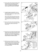
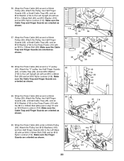
... (42) to the "U"-bracket on the Right Base (1) with an M10 x 48mm Bolt (101) and an M10 Nylon Locknut (114). 41. Attach the Pulley, a Small Cable Trap (48), and two Half Finger Guards (42) at the sec- Attach the Pulley and two Half Finger Guards (42) to the Right Base (1) with...). 1 70 42 114 39 42 48 102 1 Bracket 111 77 116 41 7 70 116 77 114 17 Wrap the Leg Lever Cable (70) under a 90mm 41 Pulley (39). Make sure the Cable Trap and Finger Guards are on the Right Base (1) with an M10 x 48mm Bolt (101) and an M10 Nylon Locknut...
... (42) to the "U"-bracket on the Right Base (1) with an M10 x 48mm Bolt (101) and an M10 Nylon Locknut (114). 41. Attach the Pulley, a Small Cable Trap (48), and two Half Finger Guards (42) at the sec- Attach the Pulley and two Half Finger Guards (42) to the Right Base (1) with...). 1 70 42 114 39 42 48 102 1 Bracket 111 77 116 41 7 70 116 77 114 17 Wrap the Leg Lever Cable (70) under a 90mm 41 Pulley (39). Make sure the Cable Trap and Finger Guards are on the Right Base (1) with an M10 x 48mm Bolt (101) and an M10 Nylon Locknut...
English Manual
Page 18
... a 90mm 50 Pulley (39). Tighten the M12 Nut (128) against the M12 Washer (129). 47. Attach the Pulley, a Small Cable Trap (48), and two Half Finger Guards (42) to hold the Cable in the indicated "U"-bracket (50) with an M10 x 110mm Bolt (73) and an M10 Nylon Locknut (114). 18 70 128... 8 68 117 115 42 39 68 48 42 114 50 102 114 8 68 40 49 137 73 48 39 68 7 114 Attach the "V"-pulley and a Cable Trap (49) to the Right Top Frame (7) with an M10 x 52mm Bolt (102) and an M10 Nylon Locknut (114). Make sure the...
... a 90mm 50 Pulley (39). Tighten the M12 Nut (128) against the M12 Washer (129). 47. Attach the Pulley, a Small Cable Trap (48), and two Half Finger Guards (42) to hold the Cable in the indicated "U"-bracket (50) with an M10 x 110mm Bolt (73) and an M10 Nylon Locknut (114). 18 70 128... 8 68 117 115 42 39 68 48 42 114 50 102 114 8 68 40 49 137 73 48 39 68 7 114 Attach the "V"-pulley and a Cable Trap (49) to the Right Top Frame (7) with an M10 x 52mm Bolt (102) and an M10 Nylon Locknut (114). Make sure the...
English Manual
Page 19
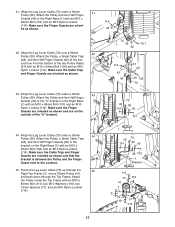
... Washer (129). 114 77 116 39 124 116 111 7 68 48 68 128 129 36 53. Attach the Pulley, two Half Finger Guards (42), a Small Cable Trap (48), and an M10 Washer (116) to the Left Seat Frame (10) with an M10 x 80mm Bolt (111), two M10 Washers (116), a 19mm Spacer... Bolt (100), an M10 Washer (116), and an M10 Nylon Locknut (114). Make sure the 16mm Spacer and the Small Cable Trap are oriented as shown. 55. Make sure the Cable Trap and Finger Guards are oriented as shown. 53 117 69 86 115 12 54 114 116 10 42 48 42...
... Washer (129). 114 77 116 39 124 116 111 7 68 48 68 128 129 36 53. Attach the Pulley, two Half Finger Guards (42), a Small Cable Trap (48), and an M10 Washer (116) to the Left Seat Frame (10) with an M10 x 80mm Bolt (111), two M10 Washers (116), a 19mm Spacer... Bolt (100), an M10 Washer (116), and an M10 Nylon Locknut (114). Make sure the 16mm Spacer and the Small Cable Trap are oriented as shown. 55. Make sure the Cable Trap and Finger Guards are oriented as shown. 53 117 69 86 115 12 54 114 116 10 42 48 42...
English Manual
Page 20
...the Left Base (2) with an M10 x 135mm Bolt (98). Attach the Pulley, two Half Finger Guards (42), a Small Cable Trap (48), and an M10 Washer (116) to the Press Frame (13) with an M10 x 52mm Bolt (102) ...and an M10 Nylon Locknut (114). Attach the Pulley, two Half Finger Guards (42), a Small Cable Trap (48), and an M10 Washer (116) to the Left Upright (5) with an M10 x 68mm Bolt (93) and... Bolt (99), an M10 Washer (116), and an M10 Nylon Locknut (114). 56. Make sure the Cable Trap and Finger Guards are oriented as shown. 20 42 114 39 48 116 42 98 13 116 42 ...
...the Left Base (2) with an M10 x 135mm Bolt (98). Attach the Pulley, two Half Finger Guards (42), a Small Cable Trap (48), and an M10 Washer (116) to the Press Frame (13) with an M10 x 52mm Bolt (102) ...and an M10 Nylon Locknut (114). Attach the Pulley, two Half Finger Guards (42), a Small Cable Trap (48), and an M10 Washer (116) to the Left Upright (5) with an M10 x 68mm Bolt (93) and... Bolt (99), an M10 Washer (116), and an M10 Nylon Locknut (114). 56. Make sure the Cable Trap and Finger Guards are oriented as shown. 20 42 114 39 48 116 42 98 13 116 42 ...

English Manual
Page 21
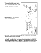
... this step with four M6 x 16mm Screws (85). 29 9 85 85 4 85 28 85 64. Note: Do not complete- 61. Attach the end of the Cable show 115 past the Locknut, as shown in the inset draw- it is tight. 132 21 Attach the Left Backrest (33) to the Backrest 64... the Upright and Backrest Frame, and turn it clockwise 121 139 until it should be tightened so that only two threads of the Leg Press Cable (69) to the Right Seat Frame (9) with an M8 Washer (117) and an M8 Nylon Locknut (115). ing. 117 50 50 69 115 Seat Assembly...
... this step with four M6 x 16mm Screws (85). 29 9 85 85 4 85 28 85 64. Note: Do not complete- 61. Attach the end of the Cable show 115 past the Locknut, as shown in the inset draw- it is tight. 132 21 Attach the Left Backrest (33) to the Backrest 64... the Upright and Backrest Frame, and turn it clockwise 121 139 until it should be tightened so that only two threads of the Leg Press Cable (69) to the Right Seat Frame (9) with an M8 Washer (117) and an M8 Nylon Locknut (115). ing. 117 50 50 69 115 Seat Assembly...
English Manual
Page 23
... Tubes. Slide two Small Foam Pads (32) onto the Pad Tube. Attach the Knee Pad (30) to remove the slack by tightening the cables. Make sure that the cables move smoothly, find and correct the problem. Slide the Pad Tube (31) through the Right Seat Frame (9). If one of the remaining parts... Dip Assist (21) 68 with the Leg Lever (11). 67 58 9 32 31 11 32 58 68. IMPORTANT: If the cables are not properly installed, they may be explained in the cables, you will be damaged when heavy weight is any slack in ADJUSTMENTS, beginning on the following page. Before using the...
... Tubes. Slide two Small Foam Pads (32) onto the Pad Tube. Attach the Knee Pad (30) to remove the slack by tightening the cables. Make sure that the cables move smoothly, find and correct the problem. Slide the Pad Tube (31) through the Right Seat Frame (9). If one of the remaining parts... Dip Assist (21) 68 with the Leg Lever (11). 67 58 9 32 31 11 32 58 68. IMPORTANT: If the cables are not properly installed, they may be explained in the cables, you will be damaged when heavy weight is any slack in ADJUSTMENTS, beginning on the following page. Before using the...
English Manual
Page 24
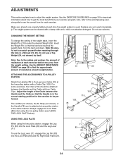
... 103 78 103 110 70 11 83 80 9 24 CHANGING THE WEIGHT SETTING To change the setting of the Chain between the Handle and the Cable with a damp cloth and a mild, non-abrasive detergent. Note: Be careful not to scratch yourself when reaching through the hole in the correct starting ...position for the exercise to find the approximate amount of resistance at the low pulley station with a Cable Clip (103). Use the WEIGHT RESISTANCE CHART on page 30 for each exercise station may vary from your exercise program. The Lat Bar (not shown...
... 103 78 103 110 70 11 83 80 9 24 CHANGING THE WEIGHT SETTING To change the setting of the Chain between the Handle and the Cable with a damp cloth and a mild, non-abrasive detergent. Note: Be careful not to scratch yourself when reaching through the hole in the correct starting ...position for the exercise to find the approximate amount of resistance at the low pulley station with a Cable Clip (103). Use the WEIGHT RESISTANCE CHART on page 30 for each exercise station may vary from your exercise program. The Lat Bar (not shown...

English Manual
Page 26
... 40 54 70 80 94 109 129 155 - 26 The other numbers refer to differences in individual weight plates as well as friction between the cables, pulleys, and weight guides. Note: The actual resistance at each arm. PRESS ARM (lbs.) 35 60 80 105 125 150 178 200 215 245 260...
... 40 54 70 80 94 109 129 155 - 26 The other numbers refer to differences in individual weight plates as well as friction between the cables, pulleys, and weight guides. Note: The actual resistance at each arm. PRESS ARM (lbs.) 35 60 80 105 125 150 178 200 215 245 260...
English Manual
Page 27
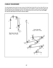
... proper routing of the Right Stack Cable (68), the Press Cable (69), the Leg Lever Cable (70), the Lat Cable (71), and the Ab Cable (72). Use the diagram to make sure that the cable traps do not touch or bind the cables. 43 1 5 2 6 Right Stack Cable (68) Length: 7 feet 7 inches 9 Press Cable (69) Length: 15 feet 7 inches 6 8 4 7 5 3 2 1 27...
... proper routing of the Right Stack Cable (68), the Press Cable (69), the Leg Lever Cable (70), the Lat Cable (71), and the Ab Cable (72). Use the diagram to make sure that the cable traps do not touch or bind the cables. 43 1 5 2 6 Right Stack Cable (68) Length: 7 feet 7 inches 9 Press Cable (69) Length: 15 feet 7 inches 6 8 4 7 5 3 2 1 27...

English Manual
Page 28
7 6 5 4 Lat Cable (71) 6 Length: 16 feet 5 2 4 1 3 8 7 3 9 1 Ab Cable (72) Length: 10 feet 3 inches 2 10 6 8 Leg Lever Cable (70) 2 Length: 21 feet 11 inches 1 4 3 7 5 28
7 6 5 4 Lat Cable (71) 6 Length: 16 feet 5 2 4 1 3 8 7 3 9 1 Ab Cable (72) Length: 10 feet 3 inches 2 10 6 8 Leg Lever Cable (70) 2 Length: 21 feet 11 inches 1 4 3 7 5 28
English Manual
Page 29
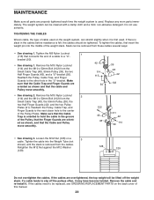
... weight system, can stretch slightly when it is first used . Remove the M10 Nylon Locknut (114) and the M10 x 52mm Bolt (102) from the Small Cable Trap (48), the 90mm Pulley (39), the two Half Finger Guards (42), and the two Pulley Plates (51). ed as shown and that the... move smoothly. 42 114 115 50 39 48 42 102 102 42 48 51 42 114 39 • See drawing 3. If the cables are orient- TIGHTENING THE CABLES Woven cable, the type of a cable to hold the cable in the groove of this manual. 29 If there is slack in the "U"-bracket. Reattach the Pulley...
... weight system, can stretch slightly when it is first used . Remove the M10 Nylon Locknut (114) and the M10 x 52mm Bolt (102) from the Small Cable Trap (48), the 90mm Pulley (39), the two Half Finger Guards (42), and the two Pulley Plates (51). ed as shown and that the... move smoothly. 42 114 115 50 39 48 42 102 102 42 48 51 42 114 39 • See drawing 3. If the cables are orient- TIGHTENING THE CABLES Woven cable, the type of a cable to hold the cable in the groove of this manual. 29 If there is slack in the "U"-bracket. Reattach the Pulley...
English Manual
Page 34
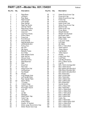
...Pulley 42 32 Half Finger Guard 43 10 Full Finger Guard 44 2 Lock Pin 45 2 Lock 46 1 Lat Bar 47 2 Handgrip 48 11 Small Cable Trap 49 6 Cable Trap 50 1 "U"-bracket 51 2 Pulley Plates 52 1 Double "U"-bracket 53 3 50mm Large Round Inner Cap 54 7 63mm Round Inner Cap 55 ...32mm Round Inner Cap Dip Arm Cap 25mm Outer Cap Cross Brace Weight Bumper Weight Tube Bumper Dip Assist Latch Right Stack Cable Press Cable Leg Lever Cable Lat Cable Ab Cable M10 x 110mm Bolt 40mm Spacer 12mm Spacer Leg Bumper 19mm Spacer Handle Large Foam Pad Lock Plate Left Base Bushing M10...
...Pulley 42 32 Half Finger Guard 43 10 Full Finger Guard 44 2 Lock Pin 45 2 Lock 46 1 Lat Bar 47 2 Handgrip 48 11 Small Cable Trap 49 6 Cable Trap 50 1 "U"-bracket 51 2 Pulley Plates 52 1 Double "U"-bracket 53 3 50mm Large Round Inner Cap 54 7 63mm Round Inner Cap 55 ...32mm Round Inner Cap Dip Arm Cap 25mm Outer Cap Cross Brace Weight Bumper Weight Tube Bumper Dip Assist Latch Right Stack Cable Press Cable Leg Lever Cable Lat Cable Ab Cable M10 x 110mm Bolt 40mm Spacer 12mm Spacer Leg Bumper 19mm Spacer Handle Large Foam Pad Lock Plate Left Base Bushing M10...
English Manual
Page 35
... M10 Nylon Locknut M8 Nylon Locknut M10 Washer M8 Washer Ab Strap Weight Pin Backrest Frame Bushing Knob Guard Short Weight Tube 16mm Spacer Large Cable Trap 28mm Round Inner Cap 127 1 128 2 129 3 130 2 131 1 132 9 133 1 134 4 135 8 136 2 137 1 138 1 139 1 140 2 # 1 # 1 # 1 # 2 25mm Round Inner Cap M12 Nut...
... M10 Nylon Locknut M8 Nylon Locknut M10 Washer M8 Washer Ab Strap Weight Pin Backrest Frame Bushing Knob Guard Short Weight Tube 16mm Spacer Large Cable Trap 28mm Round Inner Cap 127 1 128 2 129 3 130 2 131 1 132 9 133 1 134 4 135 8 136 2 137 1 138 1 139 1 140 2 # 1 # 1 # 1 # 2 25mm Round Inner Cap M12 Nut...


