
English Manual
Page 1
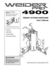
Save this equipment. Sears, Roebuck and Co., Hoffman Estates, IL 60179 Write the serial number in this manual before using this manual for reference. WEIGHT SYSTEM EXERCISER User's Manual Serial Number Decal (under seat) • Assembly • Adjustments • Troubleshooting • Part List and Drawing CAUTION Read all precautions and instructions in the space above for future reference. Model No. 831.154031 Serial No.
Save this equipment. Sears, Roebuck and Co., Hoffman Estates, IL 60179 Write the serial number in this manual before using this manual for reference. WEIGHT SYSTEM EXERCISER User's Manual Serial Number Decal (under seat) • Assembly • Adjustments • Troubleshooting • Part List and Drawing CAUTION Read all precautions and instructions in the space above for future reference. Model No. 831.154031 Serial No.
English Manual
Page 2
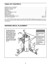
... is missing or illegible, please call toll-free 1-877-992-5999, Monday through Friday, 6 a.m. Mountain Time, to order a free replacement decal. TABLE OF CONTENTS WARNING DECAL PLACEMENT 2 IMPORTANT PRECAUTIONS 3 BEFORE YOU BEGIN 4 ASSEMBLY 5 ADJUSTMENTS 24 WEIGHT RESISTANCE CHART 26 CABLE DIAGRAM 27 MAINTENANCE 29 EXERCISE GUIDELINES 30 ORDERING REPLACEMENT PARTS Back Cover FULL 90-DAY WARRANTY Back Cover Note: A PART IDENTIFICATION CHART and a PART LIST/EXPLODED DRAWING are attached in the location shown. 2
... is missing or illegible, please call toll-free 1-877-992-5999, Monday through Friday, 6 a.m. Mountain Time, to order a free replacement decal. TABLE OF CONTENTS WARNING DECAL PLACEMENT 2 IMPORTANT PRECAUTIONS 3 BEFORE YOU BEGIN 4 ASSEMBLY 5 ADJUSTMENTS 24 WEIGHT RESISTANCE CHART 26 CABLE DIAGRAM 27 MAINTENANCE 29 EXERCISE GUIDELINES 30 ORDERING REPLACEMENT PARTS Back Cover FULL 90-DAY WARRANTY Back Cover Note: A PART IDENTIFICATION CHART and a PART LIST/EXPLODED DRAWING are attached in the location shown. 2
English Manual
Page 3
... any worn parts immediately. 6. Replace any exercise program, consult your physician. Never release the arms, leg lever, lat bar, leg press, ab strap, or handle while weights are properly tightened each time the weight system is designed to support a maximum user weight of serious injury, read the following important precautions before using the weight system. The weight system is used. Do not put the resistance system in this product. 3 Use the weight system only...
... any worn parts immediately. 6. Replace any exercise program, consult your physician. Never release the arms, leg lever, lat bar, leg press, ab strap, or handle while weights are properly tightened each time the weight system is designed to support a maximum user weight of serious injury, read the following important precautions before using the weight system. The weight system is used. Do not put the resistance system in this product. 3 Use the weight system only...
English Manual
Page 4
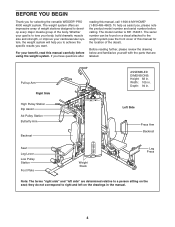
... front cover of this manual, call 1-800-4-MY-HOME® (1-800-469-4663). Pull-up Arm Right Side High Pulley Station Dip Assist Ab Pulley Station Butterfly Arm Backrest ASSEMBLED DIMENSIONS: Height: 82 in the manual. 4 The model number is to achieve the specific results you have questions after reading this manual for selecting the versatile WEIDER® PRO 4900 weight system. Left Side Press Arm Backrest Seat Leg Lever Low Pulley Station...
... front cover of this manual, call 1-800-4-MY-HOME® (1-800-469-4663). Pull-up Arm Right Side High Pulley Station Dip Assist Ab Pulley Station Butterfly Arm Backrest ASSEMBLED DIMENSIONS: Height: 82 in the manual. 4 The model number is to achieve the specific results you have questions after reading this manual for selecting the versatile WEIDER® PRO 4900 weight system. Left Side Press Arm Backrest Seat Leg Lever Low Pulley Station...
English Manual
Page 5
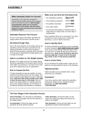
... reading the assembly instructions, please call our Customer Service Department at 1-800-4-MY-HOME® (1-800-469-4663). By setting aside plenty of evenings. You may have included a PART IDENTIFICATION CHART in the center of open the parts bag for that connect the arms to the weights. Do not dispose of soapy water, and clear tape or masking tape. Tightening Parts Tighten all parts are found...
... reading the assembly instructions, please call our Customer Service Department at 1-800-4-MY-HOME® (1-800-469-4663). By setting aside plenty of evenings. You may have included a PART IDENTIFICATION CHART in the center of open the parts bag for that connect the arms to the weights. Do not dispose of soapy water, and clear tape or masking tape. Tightening Parts Tighten all parts are found...
English Manual
Page 11
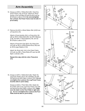
Remove the M10 x 45mm Button Bolt (105) from a Press Arm (14). Do not overtighten the Locknut; Do not overtighten the Locknut; Grease an M10 x 108mm Bolt (99). Attach a Press Handle (16) to pivot easily. Repeat this step with the Bolt and an M10 Nylon Locknut (114). the Leg Press Frame must be able to a Press Arm (14) with an M10 x 65mm Bolt (96), two M10 Washers (116...
Remove the M10 x 45mm Button Bolt (105) from a Press Arm (14). Do not overtighten the Locknut; Do not overtighten the Locknut; Grease an M10 x 108mm Bolt (99). Attach a Press Handle (16) to pivot easily. Repeat this step with the Bolt and an M10 Nylon Locknut (114). the Leg Press Frame must be able to a Press Arm (14) with an M10 x 65mm Bolt (96), two M10 Washers (116...
English Manual
Page 12
... tighten the Locknut; Slide a Large Foam Pad (79) onto the Butterfly Arm. Attach the Leg Lever (11) to pivot easily. Make sure the Dip Assist is on the Rear Upright (6). 20 6 67 Rod 114 21 116 107 116 75 64 116 114 116 108 108 5 114 Grease 21. the Dip Assist Latch must be used for this step with the Bolt...
... tighten the Locknut; Slide a Large Foam Pad (79) onto the Butterfly Arm. Attach the Leg Lever (11) to pivot easily. Make sure the Dip Assist is on the Rear Upright (6). 20 6 67 Rod 114 21 116 107 116 75 64 116 114 116 108 108 5 114 Grease 21. the Dip Assist Latch must be used for this step with the Bolt...
English Manual
Page 19
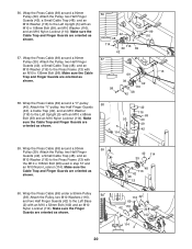
Locate the Press Cable (69). Attach the Cable to the Leg Press Frame (12) with an M10 x 103mm Bolt (106), an M10 Washer (116), and an M10 Nylon Locknut (114). Wrap the Press Cable (69) around a 90mm Pulley (39). Make sure the Finger Guards are on top of the Pulley. 52. 51. Make sure the 16mm Spacer and the Small Cable Trap are oriented...
Locate the Press Cable (69). Attach the Cable to the Leg Press Frame (12) with an M10 x 103mm Bolt (106), an M10 Washer (116), and an M10 Nylon Locknut (114). Wrap the Press Cable (69) around a 90mm Pulley (39). Make sure the Finger Guards are on top of the Pulley. 52. 51. Make sure the 16mm Spacer and the Small Cable Trap are oriented...
English Manual
Page 20
... 42 99 116 57. Attach the Pulley, two Half Finger Guards (42), a Small Cable Trap (48), and an M10 Washer (116) to the Left Base (2) with the M10 x 135mm Bolt (98) used in step 57 and an M10 Nylon Locknut (114). Wrap the Press Cable (69) around a 90mm 59 Pulley (39). Make sure the Cable Trap and Finger Guards are...
... 42 99 116 57. Attach the Pulley, two Half Finger Guards (42), a Small Cable Trap (48), and an M10 Washer (116) to the Left Base (2) with the M10 x 135mm Bolt (98) used in step 57 and an M10 Nylon Locknut (114). Wrap the Press Cable (69) around a 90mm 59 Pulley (39). Make sure the Cable Trap and Finger Guards are...

English Manual
Page 21
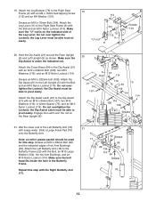
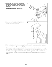
...Knob (121) into the Left Upright (5). Note: Do not complete- Attach the Seat (29) with the serial number decal on the bottom to the Backrest 64 Frame (27) with the other Seat (29) and the Left Seat Frame (not shown). 63. Repeat this step with two M6 x 16mm Screws (85), an M6 x 35mm Screw...into the Upright and Backrest Frame, and turn it clockwise 121 139 until it should be tightened so that only two threads of the Leg Press Cable (69) to the Right 63 Upright (4) with four M6 x 16mm Screws (85). ly tighten the Locknut; Attach the Left Backrest (33) to the Right Seat Frame ...
...Knob (121) into the Left Upright (5). Note: Do not complete- Attach the Seat (29) with the serial number decal on the bottom to the Backrest 64 Frame (27) with the other Seat (29) and the Left Seat Frame (not shown). 63. Repeat this step with two M6 x 16mm Screws (85), an M6 x 35mm Screw...into the Upright and Backrest Frame, and turn it clockwise 121 139 until it should be tightened so that only two threads of the Leg Press Cable (69) to the Right 63 Upright (4) with four M6 x 16mm Screws (85). ly tighten the Locknut; Attach the Left Backrest (33) to the Right Seat Frame ...
English Manual
Page 23
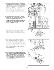
... times to remove the slack by tightening the cables. See MAINTENANCE on pages 26 and 27 of this step with four M6 x 16mm Screws (85). 30 21 85 85 69. Press two Foam Caps (58) into the Pad Tubes. Repeat this manual for proper cable routing. Attach the Knee Pad (30) to the Dip Assist (21) 68 with the Leg Lever (11...
... times to remove the slack by tightening the cables. See MAINTENANCE on pages 26 and 27 of this step with four M6 x 16mm Screws (85). 30 21 85 85 69. Press two Foam Caps (58) into the Pad Tubes. Repeat this manual for proper cable routing. Attach the Knee Pad (30) to the Dip Assist (21) 68 with the Leg Lever (11...
English Manual
Page 24
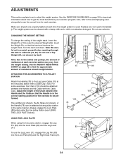
... the weight stack. Use the WEIGHT RESISTANCE CHART on page 30 for each exercise station may vary from your exercise program. CHANGING THE WEIGHT SETTING To change the setting of resistance at the low pulley station with two Cable Clips. The Lat Bar (not shown), the Ab Strap (not shown), or the Handle (78) can be performed. Always engage the Lock Plate (80) when using the low pulley station, engage the Leg Pin...
... the weight stack. Use the WEIGHT RESISTANCE CHART on page 30 for each exercise station may vary from your exercise program. CHANGING THE WEIGHT SETTING To change the setting of resistance at the low pulley station with two Cable Clips. The Lat Bar (not shown), the Ab Strap (not shown), or the Handle (78) can be performed. Always engage the Lock Plate (80) when using the low pulley station, engage the Leg Pin...

English Manual
Page 26
... each exercise station. LEG PRESS (lbs.) 27 58 89 110 147 183 208 238 263 296 327 AB STATION (lbs.) 25 40 54 70 80 94 109 129 155 - 26 WEIGHT RESISTANCE CHART The chart below shows the approximate weight resistance at each station may vary due to differences in individual weight plates as well as friction between the cables, pulleys, and weight guides...
... each exercise station. LEG PRESS (lbs.) 27 58 89 110 147 183 208 238 263 296 327 AB STATION (lbs.) 25 40 54 70 80 94 109 129 155 - 26 WEIGHT RESISTANCE CHART The chart below shows the approximate weight resistance at each station may vary due to differences in individual weight plates as well as friction between the cables, pulleys, and weight guides...
English Manual
Page 27
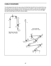
... cables. 43 1 5 2 6 Right Stack Cable (68) Length: 7 feet 7 inches 9 Press Cable (69) Length: 15 feet 7 inches 6 8 4 7 5 3 2 1 27 The numbers show the proper routing of the Right Stack Cable (68), the Press Cable (69), the Leg Lever Cable (70), the Lat Cable (71), and the Ab Cable (72). If the cables have been assembled correctly. Make sure that the cables and the cable traps have not been correctly routed, the weight bench...
... cables. 43 1 5 2 6 Right Stack Cable (68) Length: 7 feet 7 inches 9 Press Cable (69) Length: 15 feet 7 inches 6 8 4 7 5 3 2 1 27 The numbers show the proper routing of the Right Stack Cable (68), the Press Cable (69), the Leg Lever Cable (70), the Lat Cable (71), and the Ab Cable (72). If the cables have been assembled correctly. Make sure that the cables and the cable traps have not been correctly routed, the weight bench...
English Manual
Page 29
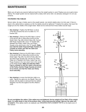
...). MAINTENANCE Make sure all parts are properly tightened each time the weight system is first used. If there is slack in the "U"-bracket. Make sure that the Cable Trap and Finger Guards are orient- Loosen the M12 Nut (128) on the back cover of the Pulley, that connects the end of the Pulley Plates. To tighten the cables, first insert the weight pin into...
...). MAINTENANCE Make sure all parts are properly tightened each time the weight system is first used. If there is slack in the "U"-bracket. Make sure that the Cable Trap and Finger Guards are orient- Loosen the M12 Nut (128) on the back cover of the Pulley, that connects the end of the Pulley Plates. To tighten the cables, first insert the weight pin into...
English Manual
Page 30
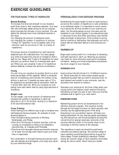
... each set . EXERCISE FORM Maintaining proper form is wrong before continuing. Never hold your heart and lungs. EXERCISE GUIDELINES THE FOUR BASIC TYPES OF WORKOUTS PERSONALIZING YOUR EXERCISE PROGRAM Muscle Building To increase the size and strength of your muscles, push them to a moderate percentage of their maximum capacity. You can complete 3 sets of resistance for 3 minutes after each exercise depends upon the individual user. formed...
... each set . EXERCISE FORM Maintaining proper form is wrong before continuing. Never hold your heart and lungs. EXERCISE GUIDELINES THE FOUR BASIC TYPES OF WORKOUTS PERSONALIZING YOUR EXERCISE PROGRAM Muscle Building To increase the size and strength of your muscles, push them to a moderate percentage of their maximum capacity. You can complete 3 sets of resistance for 3 minutes after each exercise depends upon the individual user. formed...

English Manual
Page 31
...) L. Gastrocnemius (back of sets and repetitions completed. List the date, the exercises performed, the resistance used, and the numbers of calf) 31 Sternomastoid (neck) B. Brachioradials (forearm) F. Trapezius (upper back) P. Spinae Erectors (lower back) U. Include stretches for a weight loss workout. Ease into each set. Record your arms and legs. STAYING MOTIVATED For motivation, keep a record of every month. Pectoralis Major (chest) C. Biceps (front of...
...) L. Gastrocnemius (back of sets and repetitions completed. List the date, the exercises performed, the resistance used, and the numbers of calf) 31 Sternomastoid (neck) B. Brachioradials (forearm) F. Trapezius (upper back) P. Spinae Erectors (lower back) U. Include stretches for a weight loss workout. Ease into each set. Record your arms and legs. STAYING MOTIVATED For motivation, keep a record of every month. Pectoralis Major (chest) C. Biceps (front of...

English Manual
Page 32
... Bolt (88) M6 x 22mm Bolt (109) M6 x 16mm Screw (85) M4 x 16mm Selftapping Screw (113) M8 x 86mm Shoulder Bolt (86) M10 x 86mm Bolt (92) M10 x 103mm Bolt (106) M10 x 108mm Bolt (99) M10 x 110mm Bolt (73) M10 x 118mm Bolt (100) M10 x 135mm Bolt (98) M10 x 155mm Bolt (130) The number in parentheses by each drawing is the key number of the part, from the PART LIST in assembly. PART IDENTIFICATION CHART-Model...
... Bolt (88) M6 x 22mm Bolt (109) M6 x 16mm Screw (85) M4 x 16mm Selftapping Screw (113) M8 x 86mm Shoulder Bolt (86) M10 x 86mm Bolt (92) M10 x 103mm Bolt (106) M10 x 108mm Bolt (99) M10 x 110mm Bolt (73) M10 x 118mm Bolt (100) M10 x 135mm Bolt (98) M10 x 155mm Bolt (130) The number in parentheses by each drawing is the key number of the part, from the PART LIST in assembly. PART IDENTIFICATION CHART-Model...
English Manual
Page 34
... Arm Cap 25mm Outer Cap Cross Brace Weight Bumper Weight Tube Bumper Dip Assist Latch Right Stack Cable Press Cable Leg Lever Cable Lat Cable Ab Cable M10 x 110mm Bolt 40mm Spacer 12mm Spacer Leg Bumper 19mm Spacer Handle Large Foam Pad Lock Plate Left Base Bushing M10 x 38mm Screw Leg Pin M8 x 75mm Carriage Bolt M6 x 16mm Screw M8 x 86mm Shoulder Bolt M8x 69mm Shoulder Bolt M8 x 22mm Shoulder Bolt M8 x 83mm Bolt...
... Arm Cap 25mm Outer Cap Cross Brace Weight Bumper Weight Tube Bumper Dip Assist Latch Right Stack Cable Press Cable Leg Lever Cable Lat Cable Ab Cable M10 x 110mm Bolt 40mm Spacer 12mm Spacer Leg Bumper 19mm Spacer Handle Large Foam Pad Lock Plate Left Base Bushing M10 x 38mm Screw Leg Pin M8 x 75mm Carriage Bolt M6 x 16mm Screw M8 x 86mm Shoulder Bolt M8x 69mm Shoulder Bolt M8 x 22mm Shoulder Bolt M8 x 83mm Bolt...
English Manual
Page 35
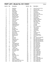
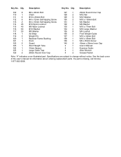
... toll-free 1-877-992-5999. Specifications are subject to change without notice. See the back cover of the user's manual for information about ordering replacement parts. Key No. Description 109 8 110 1 111 6 112 6 113 2 114 45 115 40 116 50 117 20 118 1 119 2 120 1 121 1 122 2 123 1 124 1 125 1 126 2 M6 x 22mm Bolt Chain M10 x 80mm Bolt M4 x 12mm Self-tapping Screw...
... toll-free 1-877-992-5999. Specifications are subject to change without notice. See the back cover of the user's manual for information about ordering replacement parts. Key No. Description 109 8 110 1 111 6 112 6 113 2 114 45 115 40 116 50 117 20 118 1 119 2 120 1 121 1 122 2 123 1 124 1 125 1 126 2 M6 x 22mm Bolt Chain M10 x 80mm Bolt M4 x 12mm Self-tapping Screw...


