
English Manual
Page 1
Model No. 831.154031 Serial No. WEIGHT SYSTEM EXERCISER User's Manual Serial Number Decal (under seat) • Assembly • Adjustments • Troubleshooting • Part List and Drawing CAUTION Read all precautions and instructions in the space above for future reference. Write the serial number in this manual before using this manual for reference. Sears, Roebuck and Co., Hoffman Estates, IL 60179 Save this equipment.
Model No. 831.154031 Serial No. WEIGHT SYSTEM EXERCISER User's Manual Serial Number Decal (under seat) • Assembly • Adjustments • Troubleshooting • Part List and Drawing CAUTION Read all precautions and instructions in the space above for future reference. Write the serial number in this manual before using this manual for reference. Sears, Roebuck and Co., Hoffman Estates, IL 60179 Save this equipment.
English Manual
Page 2
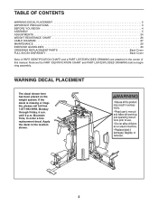
...Monday through Friday, 6 a.m. until 6 p.m. Remove the PART IDENTIFICATION CHART and PART LIST/EXPLODED DRAWING before beginning assembly. Apply the decal in the center of this manual. Mountain Time, to order a free replacement decal. WARNING DECAL PLACEMENT The decal shown here has been placed on... the weight system. TABLE OF CONTENTS WARNING DECAL PLACEMENT 2 IMPORTANT PRECAUTIONS 3 BEFORE YOU BEGIN 4 ASSEMBLY 5 ADJUSTMENTS 24 WEIGHT ...
...Monday through Friday, 6 a.m. until 6 p.m. Remove the PART IDENTIFICATION CHART and PART LIST/EXPLODED DRAWING before beginning assembly. Apply the decal in the center of this manual. Mountain Time, to order a free replacement decal. WARNING DECAL PLACEMENT The decal shown here has been placed on... the weight system. TABLE OF CONTENTS WARNING DECAL PLACEMENT 2 IMPORTANT PRECAUTIONS 3 BEFORE YOU BEGIN 4 ASSEMBLY 5 ADJUSTMENTS 24 WEIGHT ...
English Manual
Page 4
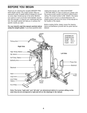
... weight system will help us assist you have questions after reading this manual carefully before calling. To help you to the weight system (see the front cover of this manual for selecting the versatile WEIDER® PRO 4900 weight system. Before reading further, please review the drawing below and ... of the body. Pull-up Arm Right Side High Pulley Station Dip Assist Ab Pulley Station Butterfly Arm Backrest ASSEMBLED DIMENSIONS: Height: 82 in . Width: 105 in the manual. 4 Left Side Press Arm Backrest Seat Leg Lever Low Pulley Station Foot Plate Weight Stack Leg Press Note...
... weight system will help us assist you have questions after reading this manual carefully before calling. To help you to the weight system (see the front cover of this manual for selecting the versatile WEIDER® PRO 4900 weight system. Before reading further, please review the drawing below and ... of the body. Pull-up Arm Right Side High Pulley Station Dip Assist Ab Pulley Station Butterfly Arm Backrest ASSEMBLED DIMENSIONS: Height: 82 in . Width: 105 in the manual. 4 Left Side Press Arm Backrest Seat Leg Lever Low Pulley Station Foot Plate Weight Stack Leg Press Note...
English Manual
Page 5
... found in this stage you will assemble the seats and the backrests. 5 Arm Assembly-During this manual. Before beginning assembly, make sure all parts of ratchet wrenches. Cable Assembly-During this manual is not in a cleared area and remove the packing materials. Assembly Requires Two Persons For your convenience and safety, assemble the weight system with the help...
... found in this stage you will assemble the seats and the backrests. 5 Arm Assembly-During this manual. Before beginning assembly, make sure all parts of ratchet wrenches. Cable Assembly-During this manual is not in a cleared area and remove the packing materials. Assembly Requires Two Persons For your convenience and safety, assemble the weight system with the help...
English Manual
Page 6
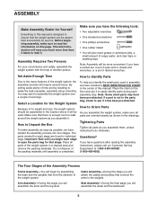
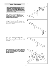
... them in place. 2. Do not tight- Note: It may be help - Insert four M8 x 75mm Carriage Bolts (84) up 2 through the Rear Base (3). Before beginning assembly, make sure you understand the information in place. 1 84 84 2 84 84 3 4. ful to place a piece of tape over the bolt heads to hold them... (1) with two M8 x 83mm Bolts (89) and two M8 Nylon Locknuts (115). Attach the Rear Base (3) and the Left Base (2) to place a piece of this manual for help identifying small parts. Frame Assembly 1 1. en the Locknuts yet. 84 3 89 89 1 6 115 115 2
... them in place. 2. Do not tight- Note: It may be help - Insert four M8 x 75mm Carriage Bolts (84) up 2 through the Rear Base (3). Before beginning assembly, make sure you understand the information in place. 1 84 84 2 84 84 3 4. ful to place a piece of tape over the bolt heads to hold them... (1) with two M8 x 83mm Bolts (89) and two M8 Nylon Locknuts (115). Attach the Rear Base (3) and the Left Base (2) to place a piece of this manual for help identifying small parts. Frame Assembly 1 1. en the Locknuts yet. 84 3 89 89 1 6 115 115 2

English Manual
Page 32
If a part is the key number of the part, from the PART LIST in the center of this manual. The number in parentheses by each drawing is not in assembly. Note: Some small parts may have been pre-attached. PART IDENTIFICATION CHART-Model No. 831.154031 R0804A Refer to the drawings below to...
If a part is the key number of the part, from the PART LIST in the center of this manual. The number in parentheses by each drawing is not in assembly. Note: Some small parts may have been pre-attached. PART IDENTIFICATION CHART-Model No. 831.154031 R0804A Refer to the drawings below to...


