
English Manual
Page 1
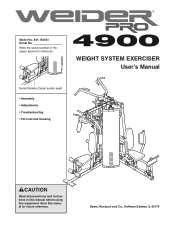
Sears, Roebuck and Co., Hoffman Estates, IL 60179 Save this equipment. Model No. 831.154031 Serial No. WEIGHT SYSTEM EXERCISER User's Manual Serial Number Decal (under seat) • Assembly • Adjustments • Troubleshooting • Part List and Drawing CAUTION Read all precautions and instructions in the space above for future reference. Write the serial number in this manual before using this manual for reference.
Sears, Roebuck and Co., Hoffman Estates, IL 60179 Save this equipment. Model No. 831.154031 Serial No. WEIGHT SYSTEM EXERCISER User's Manual Serial Number Decal (under seat) • Assembly • Adjustments • Troubleshooting • Part List and Drawing CAUTION Read all precautions and instructions in the space above for future reference. Write the serial number in this manual before using this manual for reference.
English Manual
Page 2
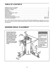
... is missing or illegible, please call toll-free 1-877-992-5999, Monday through Friday, 6 a.m. TABLE OF CONTENTS WARNING DECAL PLACEMENT 2 IMPORTANT PRECAUTIONS 3 BEFORE YOU BEGIN 4 ASSEMBLY 5 ADJUSTMENTS 24 WEIGHT RESISTANCE CHART 26 CABLE DIAGRAM 27 MAINTENANCE 29 EXERCISE GUIDELINES 30 ORDERING REPLACEMENT PARTS Back Cover FULL 90-DAY WARRANTY Back Cover... IDENTIFICATION CHART and a PART LIST/EXPLODED DRAWING are attached in the location shown. 2 Remove the PART IDENTIFICATION CHART and PART LIST/EXPLODED DRAWING before beginning assembly.
... is missing or illegible, please call toll-free 1-877-992-5999, Monday through Friday, 6 a.m. TABLE OF CONTENTS WARNING DECAL PLACEMENT 2 IMPORTANT PRECAUTIONS 3 BEFORE YOU BEGIN 4 ASSEMBLY 5 ADJUSTMENTS 24 WEIGHT RESISTANCE CHART 26 CABLE DIAGRAM 27 MAINTENANCE 29 EXERCISE GUIDELINES 30 ORDERING REPLACEMENT PARTS Back Cover FULL 90-DAY WARRANTY Back Cover... IDENTIFICATION CHART and a PART LIST/EXPLODED DRAWING are attached in the location shown. 2 Remove the PART IDENTIFICATION CHART and PART LIST/EXPLODED DRAWING before beginning assembly.
English Manual
Page 4
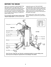
... Side High Pulley Station Dip Assist Ab Pulley Station Butterfly Arm Backrest ASSEMBLED DIMENSIONS: Height: 82 in . they do not correspond to a person sitting on the seat; If you have questions after reading this manual for selecting the versatile WEIDER® PRO 4900 weight system. Before reading further, please review the drawing below and...
... Side High Pulley Station Dip Assist Ab Pulley Station Butterfly Arm Backrest ASSEMBLED DIMENSIONS: Height: 82 in . they do not correspond to a person sitting on the seat; If you have questions after reading this manual for selecting the versatile WEIDER® PRO 4900 weight system. Before reading further, please review the drawing below and...
English Manual
Page 5
... around the weight system as you have included a PART IDENTIFICATION CHART in the center of time and by anyone. The Four Stages of the Assembly Process Frame Assembly-You will begin each stage to open -end or closed-end wrenches, or a set of its weight and size, the weight system should be... a part is designed to ensure that the weight system can be more time than it takes to Unpack the Box To make the task enjoyable, assembly will attach the cables and pulleys that there is completed. Questions? You may have a socket set, a set of open the parts bag for the Weight...
... around the weight system as you have included a PART IDENTIFICATION CHART in the center of time and by anyone. The Four Stages of the Assembly Process Frame Assembly-You will begin each stage to open -end or closed-end wrenches, or a set of its weight and size, the weight system should be... a part is designed to ensure that the weight system can be more time than it takes to Unpack the Box To make the task enjoyable, assembly will attach the cables and pulleys that there is completed. Questions? You may have a socket set, a set of open the parts bag for the Weight...
English Manual
Page 6
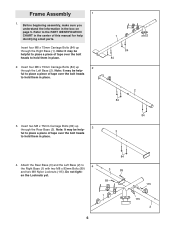
...of tape over the bolt heads to hold them in the box on page 5. en the Locknuts yet. 84 3 89 89 1 6 115 115 2 Before beginning assembly, make sure you understand the information in place. 2. Insert four M8 x 75mm Carriage Bolts (84) up through the Rear Base (3). Attach the Rear Base (3) ... identifying small parts. Refer to the PART IDENTIFICATION CHART in the center of tape over the bolt heads to hold them in place. 3. Frame Assembly 1 1. ful to 4 the Right Base (1) with two M8 x 83mm Bolts (89) and two M8 Nylon Locknuts (115). Note: It may be help...
...of tape over the bolt heads to hold them in the box on page 5. en the Locknuts yet. 84 3 89 89 1 6 115 115 2 Before beginning assembly, make sure you understand the information in place. 2. Insert four M8 x 75mm Carriage Bolts (84) up through the Rear Base (3). Attach the Rear Base (3) ... identifying small parts. Refer to the PART IDENTIFICATION CHART in the center of tape over the bolt heads to hold them in place. 3. Frame Assembly 1 1. ful to 4 the Right Base (1) with two M8 x 83mm Bolts (89) and two M8 Nylon Locknuts (115). Note: It may be help...
English Manual
Page 11
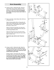
... two M8 x 70mm Bolts (97) and two M8 Nylon Locknuts (115). Grease an M10 x 108mm Bolt (99). Orient the Press Frame (13) as shown. Arm Assembly 16 16. Do not overtighten the Locknut; Remove the M10 x 45mm Button Bolt (105) from a Press Arm (14). Grease an M10 x 108mm Bolt (99).
... two M8 x 70mm Bolts (97) and two M8 Nylon Locknuts (115). Grease an M10 x 108mm Bolt (99). Orient the Press Frame (13) as shown. Arm Assembly 16 16. Do not overtighten the Locknut; Remove the M10 x 45mm Button Bolt (105) from a Press Arm (14). Grease an M10 x 108mm Bolt (99).
English Manual
Page 13
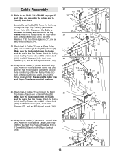
... Washers (116), two 19mm Spacers (77), and an M10 Nylon Locknut (114). 23. Make sure the Cable Trap and Finger Guards are oriented as you assemble the cables and to identify the cables. Wrap the Lat Cable (71) around a 115mm Pulley 26 (41). Make sure the Cable is between the Pulley... the Top Frame. Route the Lat Cable (71) over a 90mm Pulley (39) and down through the Right Top Frame (7) and over a 90mm Pulley (39). Cable Assembly 22.
... Washers (116), two 19mm Spacers (77), and an M10 Nylon Locknut (114). 23. Make sure the Cable Trap and Finger Guards are oriented as you assemble the cables and to identify the cables. Wrap the Lat Cable (71) around a 115mm Pulley 26 (41). Make sure the Cable is between the Pulley... the Top Frame. Route the Lat Cable (71) over a 90mm Pulley (39) and down through the Right Top Frame (7) and over a 90mm Pulley (39). Cable Assembly 22.

English Manual
Page 21
... Washer (117) and an M8 Nylon Locknut (115). Note: Do not complete- it is tight. 132 21 61. ing. 117 50 50 69 115 Seat Assembly 62 62. Repeat this step with two M6 x 16mm Screws (85), an M6 x 35mm Screw (139), and an M6 Washer 85 27 5 (132). 33 Slide...
... Washer (117) and an M8 Nylon Locknut (115). Note: Do not complete- it is tight. 132 21 61. ing. 117 50 50 69 115 Seat Assembly 62 62. Repeat this step with two M6 x 16mm Screws (85), an M6 x 35mm Screw (139), and an M6 Washer 85 27 5 (132). 33 Slide...
English Manual
Page 27
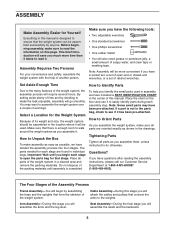
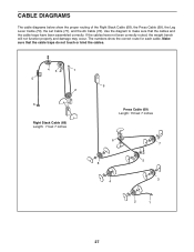
... and the cable traps have not been correctly routed, the weight bench will not function properly and damage may occur. If the cables have been assembled correctly. CABLE DIAGRAMS The cable diagrams below show the correct route for each cable. The numbers show the proper routing of the Right Stack Cable...
... and the cable traps have not been correctly routed, the weight bench will not function properly and damage may occur. If the cables have been assembled correctly. CABLE DIAGRAMS The cable diagrams below show the correct route for each cable. The numbers show the proper routing of the Right Stack Cable...

English Manual
Page 32
... in the center of this manual. The number in parentheses by each drawing is the key number of the part, from the PART LIST in assembly. Note: Some small parts may have been pre-attached. M8 x 80mm Bolt (94) M10 x 45mm Bolt (138) M8 x 75mm Carriage Bolt (84) M10 x 45mm Button...
... in the center of this manual. The number in parentheses by each drawing is the key number of the part, from the PART LIST in assembly. Note: Some small parts may have been pre-attached. M8 x 80mm Bolt (94) M10 x 45mm Bolt (138) M8 x 75mm Carriage Bolt (84) M10 x 45mm Button...


