

Uk Manual
Page 1
USER'S MANUAL Serial Number Decal (Under Seat) QUESTIONS? As a manufacturer, we are missing or damaged parts, please call: 08457 089 009 Or write: ICON Health & Fitness, Ltd. Model No. Save this equipment. If you have questions, or if there are committed to providing complete customer satisfaction.... Estate Revie Road, Beeston Leeds, LS11 8JG UK email: [email protected] CAUTION Read all precautions and instructions in the space above for future reference. WEEVSY2826.0 Serial No. Write the serial number in this manual before using this manual for future reference.
USER'S MANUAL Serial Number Decal (Under Seat) QUESTIONS? As a manufacturer, we are missing or damaged parts, please call: 08457 089 009 Or write: ICON Health & Fitness, Ltd. Model No. Save this equipment. If you have questions, or if there are committed to providing complete customer satisfaction.... Estate Revie Road, Beeston Leeds, LS11 8JG UK email: [email protected] CAUTION Read all precautions and instructions in the space above for future reference. WEEVSY2826.0 Serial No. Write the serial number in this manual before using this manual for future reference.
Uk Manual
Page 2
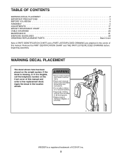
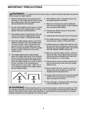
... is missing, or if it is a registered trademark of this manual and order a free replacement decal. Apply the decal in the centre of ICON IP, Inc. 2 TABLE OF CONTENTS WARNING DECAL PLACEMENT 2 IMPORTANT PRECAUTIONS 3 BEFORE YOU BEGIN 4 ASSEMBLY 5 ADJUSTMENTS 17 WEIGHT RESISTANCE CHART 19 CABLE DIAGRAMS 20 MAINTENANCE 21 EXERCISE GUIDELINES 22 ORDERING REPLACEMENT PARTS Back Cover Note: A PART IDENTIFICATION CHART and a PART LIST/EXPLODED DRAWING are attached in the location shown.
... is missing, or if it is a registered trademark of this manual and order a free replacement decal. Apply the decal in the centre of ICON IP, Inc. 2 TABLE OF CONTENTS WARNING DECAL PLACEMENT 2 IMPORTANT PRECAUTIONS 3 BEFORE YOU BEGIN 4 ASSEMBLY 5 ADJUSTMENTS 17 WEIGHT RESISTANCE CHART 19 CABLE DIAGRAMS 20 MAINTENANCE 21 EXERCISE GUIDELINES 22 ORDERING REPLACEMENT PARTS Back Cover Note: A PART IDENTIFICATION CHART and a PART LIST/EXPLODED DRAWING are attached in the location shown.
Uk Manual
Page 3
... with pre-existing health problems. Read all precautions. 3. Never release the arms, leg lever, lat bar, or handle strap while weights are adequately informed of all instructions before using the weight system. 1. If you are exercising, stop immediately and cool down. To prevent access to ensure that the cables are properly tightened each time the weight system is the responsibility of the owner to the weight stack, place the...
... with pre-existing health problems. Read all precautions. 3. Never release the arms, leg lever, lat bar, or handle strap while weights are adequately informed of all instructions before using the weight system. 1. If you are exercising, stop immediately and cool down. To prevent access to ensure that the cables are properly tightened each time the weight system is the responsibility of the owner to the weight stack, place the...
Uk Manual
Page 4
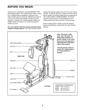
... you to the weight system (see the front cover of the body. The serial number can be found on the drawings in .) 4 Shroud Curl Pad Seat Leg Lever Low Pulley Station Foot Plate Weights Anchor Hole* Left Side ASSEMBLED DIMENSIONS: Height: 193 cm (76 in.) Width: 94 cm (37 in.) Depth: 122 cm (48 in this manual). High Pulley Station Arm Pin Arm Right Side Backrest...
... you to the weight system (see the front cover of the body. The serial number can be found on the drawings in .) 4 Shroud Curl Pad Seat Leg Lever Low Pulley Station Foot Plate Weights Anchor Hole* Left Side ASSEMBLED DIMENSIONS: Height: 193 cm (76 in.) Width: 94 cm (37 in.) Depth: 122 cm (48 in this manual). High Pulley Station Arm Pin Arm Right Side Backrest...
Uk Manual
Page 5
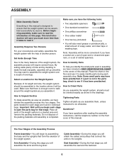
... a socket set, a set of the Assembly Process Frame Assembly-You will assemble the arms and the leg lever. How to Identify Parts To help of its weight and size, the weight system should be assembled in the location where it will assemble the seat and the backrest. 5 Assembly Requires Two Persons For your convenience and safety, assemble the weight system with the help you assemble them, unless instructed to open -end...
... a socket set, a set of the Assembly Process Frame Assembly-You will assemble the arms and the leg lever. How to Identify Parts To help of its weight and size, the weight system should be assembled in the location where it will assemble the seat and the backrest. 5 Assembly Requires Two Persons For your convenience and safety, assemble the weight system with the help you assemble them, unless instructed to open -end...
Uk Manual
Page 6
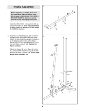
... to the Base (1) with two M10 x 80mm Button Bolts (71), two M10 Washers (57), and two M10 Nylon Locknuts (56). Tighten the Nylon Locknuts. Frame Assembly 1 1. Attach the Upright (3) to the lower ends. Attach the two Weight Guides and the Base (1) to place a piece of this manual for help identifying small parts. Do not tighten the Nylon Locknuts yet. 1 78 78 21 3 58...
... to the Base (1) with two M10 x 80mm Button Bolts (71), two M10 Washers (57), and two M10 Nylon Locknuts (56). Tighten the Nylon Locknuts. Frame Assembly 1 1. Attach the Upright (3) to the lower ends. Attach the two Weight Guides and the Base (1) to place a piece of this manual for help identifying small parts. Do not tighten the Nylon Locknuts yet. 1 78 78 21 3 58...
Uk Manual
Page 9
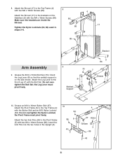
... brackets are inside the Shroud. 17 Tighten the Nylon Locknuts (56, 58) used in the Upright (3). 10 56 86 5 40 4 67 Holes Grease 3 86 40 9 Grease an M10 x 90mm Button Bolt (67). Do not overtighten the Bolt Set; Attach the Leg Lever to the Top Frame (4) with two M4 x 16mm Screws (86). Insert the Arm Pins into the two holes in 86 steps 2-6. 86 Bracket Arm Assembly 9.
... brackets are inside the Shroud. 17 Tighten the Nylon Locknuts (56, 58) used in the Upright (3). 10 56 86 5 40 4 67 Holes Grease 3 86 40 9 Grease an M10 x 90mm Button Bolt (67). Do not overtighten the Bolt Set; Attach the Leg Lever to the Top Frame (4) with two M4 x 16mm Screws (86). Insert the Arm Pins into the two holes in 86 steps 2-6. 86 Bracket Arm Assembly 9.
Uk Manual
Page 10
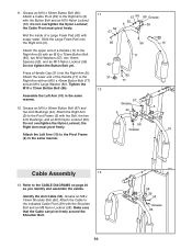
... (56). Press a Handle Cap (31) into the Right Arm (9). Assemble the Left Arm (10) in the same manner. 11 57 56 66 Grease 52 9 39 52 57 85 56 10 11 42 31 12 80 77 67 Grease 5 44 9 56 Grease 10 Cable Assembly 13 13. Grease an M10 x 90mm Button Bolt (67) and two Arm Bushings (44). Attach a Cable Pivot (39) to the CABLE DIAGRAMS on...
... (56). Press a Handle Cap (31) into the Right Arm (9). Assemble the Left Arm (10) in the same manner. 11 57 56 66 Grease 52 9 39 52 57 85 56 10 11 42 31 12 80 77 67 Grease 5 44 9 56 Grease 10 Cable Assembly 13 13. Grease an M10 x 90mm Button Bolt (67) and two Arm Bushings (44). Attach a Cable Pivot (39) to the CABLE DIAGRAMS on...
Uk Manual
Page 12
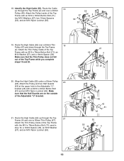
... Attach the Pulley inside of the Top Frame with an M10 x 45mm Button Bolt (81) and an M10 Nylon Locknut (56). Route the High Cable (55) over a 90mm Thin Pulley (47). Route the High Cable (55) up through the Top Frame (4). Make sure that the Thin Pulley does not fall out of the Top Frame with the M10 x 78mm Button Bolt (71) used...
... Attach the Pulley inside of the Top Frame with an M10 x 45mm Button Bolt (81) and an M10 Nylon Locknut (56). Route the High Cable (55) over a 90mm Thin Pulley (47). Route the High Cable (55) up through the Top Frame (4). Make sure that the Thin Pulley does not fall out of the Top Frame with the M10 x 78mm Button Bolt (71) used...
Uk Manual
Page 15
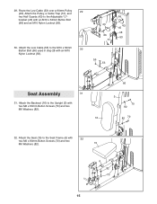
... 3 70 82 82 70 32. Attach the Seat (15) to the Upright (3) with 32 two M6 x 80mm Button Screws (70) and two M6 Washers (82). 15 6 82 70 15 Attach the Pulley, a Cable Trap (51), and two Half Guards (43) to the M10 x 52mm 30 Button Bolt (66) used in step 28 with an M10 x 52mm Button Bolt (66) and an M10 Nylon Locknut...
... 3 70 82 82 70 32. Attach the Seat (15) to the Upright (3) with 32 two M6 x 80mm Button Screws (70) and two M6 Washers (82). 15 6 82 70 15 Attach the Pulley, a Cable Trap (51), and two Half Guards (43) to the M10 x 52mm 30 Button Bolt (66) used in step 28 with an M10 x 52mm Button Bolt (66) and an M10 Nylon Locknut...
Uk Manual
Page 16
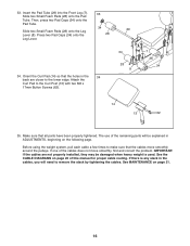
...) onto the Leg 29 Lever (8). Attach the Curl Pad to make sure that all parts have been properly tightened. See MAINTENANCE on page 20 of this manual for proper cable routing. Make sure that the cables move smoothly, find and correct the problem. If one of the remaining parts will need to the lower edge. IMPORTANT: If the cables are not properly installed, they may be...
...) onto the Leg 29 Lever (8). Attach the Curl Pad to make sure that all parts have been properly tightened. See MAINTENANCE on page 20 of this manual for proper cable routing. Make sure that the cables move smoothly, find and correct the problem. If one of the remaining parts will need to the lower edge. IMPORTANT: If the cables are not properly installed, they may be...
Uk Manual
Page 17
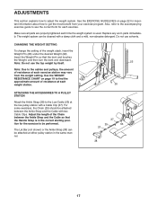
.... Note: Due to the cables and pulleys, the amount of resistance at each exercise station may vary from your exercise program. The weight system can be attached between the Ankle Strap and the Cable so that the bent end touches the Weight, and then turn the bent end downward. Also, refer to the accompanying exercise guide to adjust the weight system. The Lat Bar (not shown) or the...
.... Note: Due to the cables and pulleys, the amount of resistance at each exercise station may vary from your exercise program. The weight system can be attached between the Ankle Strap and the Cable so that the bent end touches the Weight, and then turn the bent end downward. Also, refer to the accompanying exercise guide to adjust the weight system. The Lat Bar (not shown) or the...
Uk Manual
Page 19
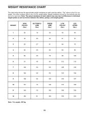
...the 12.5 lb. Note: The actual resistance at each exercise station. The other numbers refer to the 6 lb. equals .454 kg. 19 top weight. WEIGHT 1 HIGH PULLEY (lbs.) 25 BUTTERFLY ARM (lbs.) 16 PRESS ARM (lbs.) 30 LOW PULLEY (lbs.) 42 LEG LEVER (lbs.) 40 2 40 20 40... 210 Note: 1 lb. Weight resistance shown for the butterfly arm station is for each arm. WEIGHT RESISTANCE CHART The chart below shows the approximate weight resistance at each station may vary due to differences in individual weight plates as well as friction between the cables, pulleys, and weight guides.
...the 12.5 lb. Note: The actual resistance at each exercise station. The other numbers refer to the 6 lb. equals .454 kg. 19 top weight. WEIGHT 1 HIGH PULLEY (lbs.) 25 BUTTERFLY ARM (lbs.) 16 PRESS ARM (lbs.) 30 LOW PULLEY (lbs.) 42 LEG LEVER (lbs.) 40 2 40 20 40... 210 Note: 1 lb. Weight resistance shown for the butterfly arm station is for each arm. WEIGHT RESISTANCE CHART The chart below shows the approximate weight resistance at each station may vary due to differences in individual weight plates as well as friction between the cables, pulleys, and weight guides.

Uk Manual
Page 20
The numbers show the proper routing of the Low Cable (53), the Arm Cable (54), and the High Cable (55). Make sure that the cables, cable traps, and finger guards have not been correctly routed, the weight system will not function properly and damage may occur. CABLE DIAGRAMS The cable diagrams below show the correct route for each cable. If the cables have been assembled correctly. Use the diagrams to make...
The numbers show the proper routing of the Low Cable (53), the Arm Cable (54), and the High Cable (55). Make sure that the cables, cable traps, and finger guards have not been correctly routed, the weight system will not function properly and damage may occur. CABLE DIAGRAMS The cable diagrams below show the correct route for each cable. If the cables have been assembled correctly. Use the diagrams to make...
Uk Manual
Page 21
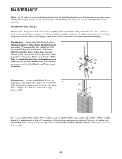
... Button Bolt (66) from these cables several ways: See drawing 1. If a cable tends to hold the cable in the cables before resistance is felt, the cables should be cleaned with a damp cloth and a mild, non-abrasive detergent. The weight system can be tightened. Do not use solvents. TIGHTENING THE CABLES Woven cable, the type of the Pulley, that the Cable Trap is oriented to slip off the weight...
... Button Bolt (66) from these cables several ways: See drawing 1. If a cable tends to hold the cable in the cables before resistance is felt, the cables should be cleaned with a damp cloth and a mild, non-abrasive detergent. The weight system can be tightened. Do not use solvents. TIGHTENING THE CABLES Woven cable, the type of the Pulley, that the Cable Trap is oriented to slip off the weight...
Uk Manual
Page 22
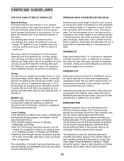
... workouts, vary the exercises from both strength training and aerobic exercise for you perform. You can adjust the intensity level of an individual exercise in each set . You must gauge your limits and select the amount of resistance that is right for at any exercise program. When you want to develop most. Weight Loss To lose weight, use a low amount of resistance and increase the number...
... workouts, vary the exercises from both strength training and aerobic exercise for you perform. You can adjust the intensity level of an individual exercise in each set . You must gauge your limits and select the amount of resistance that is right for at any exercise program. When you want to develop most. Weight Loss To lose weight, use a low amount of resistance and increase the number...
Uk Manual
Page 23
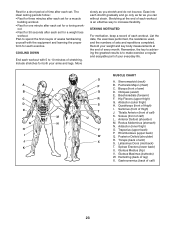
...; Rest for three minutes after each set for a muscle building workout. • Rest for one minute after each workout. Brachioradials (forearm) F. Move slowly as you stretch and do not bounce. Hamstring (back of sets and repetitions completed. Include stretches for a toning work- List the date, the exercises performed, the resistance used, and the numbers of leg) X. Tibialis Anterior (front of calf) L. Soleus...
...; Rest for three minutes after each set for a muscle building workout. • Rest for one minute after each workout. Brachioradials (forearm) F. Move slowly as you stretch and do not bounce. Hamstring (back of sets and repetitions completed. Include stretches for a toning work- List the date, the exercises performed, the resistance used, and the numbers of leg) X. Tibialis Anterior (front of calf) L. Soleus...
Uk Manual
Page 24
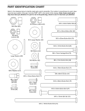
... Button Bolt (68) M10 x 78mm Button Bolt (71) M6 x 80mm Screw (70) M10 x 80mm Button Bolt (79) M10 x 90mm Button Bolt (67) M10 x 70mm Bolt Set (73) M10 x 155mm Button Bolt (74) The number in parentheses by each drawing is not in the parts bag, check to identify small parts used in the centre of the part, from the PART LIST in assembly. Note: Some small parts may have been pre-attached. PART IDENTIFICATION CHART...
... Button Bolt (68) M10 x 78mm Button Bolt (71) M6 x 80mm Screw (70) M10 x 80mm Button Bolt (79) M10 x 90mm Button Bolt (67) M10 x 70mm Bolt Set (73) M10 x 155mm Button Bolt (74) The number in parentheses by each drawing is not in the parts bag, check to identify small parts used in the centre of the part, from the PART LIST in assembly. Note: Some small parts may have been pre-attached. PART IDENTIFICATION CHART...

Uk Manual
Page 25
... Button Bolt 76 2 13mm Spacer 77 2 M10 x 40mm Button Bolt 78 4 M8 x 74mm Carriage Bolt 79 2 M10 x 80mm Button Bolt 80 2 M10 Large Washer 81 3 M10 x 45mm Button Bolt 82 4 M6 Washer 83 2 57mm Thick Round Inner Cap 84 4 M4 x 10mm Screw 85 3 M10 x 72mm Button Bolt 86 6 M4 x 16mm Screw 87 1 M12 Nut 88 1 Large Washer # 1 User's Manual # 1 Exercise Guide # 2 Grease Packet # 1 Hex Key Note: "#" indicates a non-illustrated part. Specifications...
... Button Bolt 76 2 13mm Spacer 77 2 M10 x 40mm Button Bolt 78 4 M8 x 74mm Carriage Bolt 79 2 M10 x 80mm Button Bolt 80 2 M10 Large Washer 81 3 M10 x 45mm Button Bolt 82 4 M6 Washer 83 2 57mm Thick Round Inner Cap 84 4 M4 x 10mm Screw 85 3 M10 x 72mm Button Bolt 86 6 M4 x 16mm Screw 87 1 M12 Nut 88 1 Large Washer # 1 User's Manual # 1 Exercise Guide # 2 Grease Packet # 1 Hex Key Note: "#" indicates a non-illustrated part. Specifications...
Uk Manual
Page 28
... of the product (WEIDER PRO 4000 weight system) • the SERIAL NUMBER of the product (see the front cover of this manual) • the KEY NUMBER and DESCRIPTION of the part(s) (see the PART LIST and EXPLODED DRAWING in the centre of this manual) Part No. 241168 R0706A Printed in China © 2006 ICON IP, Inc. ORDERING REPLACEMENT PARTS To order replacement parts, contact the ICON Health & Fitness, Ltd. office, or write: ICON Health & Fitness, Ltd.
... of the product (WEIDER PRO 4000 weight system) • the SERIAL NUMBER of the product (see the front cover of this manual) • the KEY NUMBER and DESCRIPTION of the part(s) (see the PART LIST and EXPLODED DRAWING in the centre of this manual) Part No. 241168 R0706A Printed in China © 2006 ICON IP, Inc. ORDERING REPLACEMENT PARTS To order replacement parts, contact the ICON Health & Fitness, Ltd. office, or write: ICON Health & Fitness, Ltd.


