
User Manual
Page 1
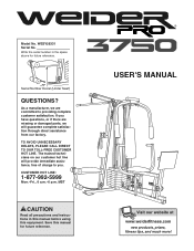
... using this manual for future reference. TO AVOID UNNECESSARY DELAYS, PLEASE CALL DIRECT TO OUR TOLL-FREE CUSTOMER HOT LINE. Save this equipment. Serial Number Decal (Under Seat) QUESTIONS? If you . MST CAUTION Read all precautions and instructions in the space above for future reference. USER'S MANUAL Visit our website at www.weiderfitness.com new products, prizes, fitness tips, and much more! Model...
... using this manual for future reference. TO AVOID UNNECESSARY DELAYS, PLEASE CALL DIRECT TO OUR TOLL-FREE CUSTOMER HOT LINE. Save this equipment. Serial Number Decal (Under Seat) QUESTIONS? If you . MST CAUTION Read all precautions and instructions in the space above for future reference. USER'S MANUAL Visit our website at www.weiderfitness.com new products, prizes, fitness tips, and much more! Model...
User Manual
Page 2
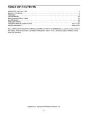
WEIDER is a registered trademark of this manual. Remove the PART IDENTIFICATION CHART and the PART LIST/EXPLODED DRAWING before beginning assembly. TABLE OF CONTENTS IMPORTANT PRECAUTIONS 3 BEFORE YOU BEGIN 4 ASSEMBLY 5 ADJUSTMENTS 22 WEIGHT RESISTANCE CHART 24 MAINTENANCE 25 CABLE DIAGRAMS 26 ORDERING REPLACEMENT PARTS Back Cover LIMITED WARRANTY Back Cover Note: A PART IDENTIFICATION CHART and a PART LIST/EXPLODED DRAWING are attached in the center of ICON IP, Inc. 2
WEIDER is a registered trademark of this manual. Remove the PART IDENTIFICATION CHART and the PART LIST/EXPLODED DRAWING before beginning assembly. TABLE OF CONTENTS IMPORTANT PRECAUTIONS 3 BEFORE YOU BEGIN 4 ASSEMBLY 5 ADJUSTMENTS 22 WEIGHT RESISTANCE CHART 24 MAINTENANCE 25 CABLE DIAGRAMS 26 ORDERING REPLACEMENT PARTS Back Cover LIMITED WARRANTY Back Cover Note: A PART IDENTIFICATION CHART and a PART LIST/EXPLODED DRAWING are attached in the center of ICON IP, Inc. 2
User Manual
Page 3
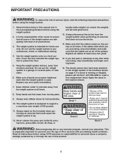
... covered patio, or near water. 6. Always wear athletic shoes for home use . • Do not allow children on a level surface. Never release the press arm, butterfly arms, leg lever, press plate, lat bar, ab strap, or Decal 3 WARNING: Before beginning this product. 3 The weight system is the responsibility of all instructions before using the weight system. 1. Make sure that could cause the weight system to support a a maximum user weight...
... covered patio, or near water. 6. Always wear athletic shoes for home use . • Do not allow children on a level surface. Never release the press arm, butterfly arms, leg lever, press plate, lat bar, ab strap, or Decal 3 WARNING: Before beginning this product. 3 The weight system is the responsibility of all instructions before using the weight system. 1. Make sure that could cause the weight system to support a a maximum user weight...
User Manual
Page 4
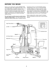
... to achieve the specific results you , please note the product model number and serial number before using the weight system. If you for selecting the versatile WEIDER® PRO 3750 weight system. To help you to develop every major muscle group of this manual). until 6 p.m. High Pulley Station Lat Bar Ab Pulley Station Backrests Decal 3 Decal 3 ASSEMBLED DIMENSIONS: Height: 78 in . Before reading further, please review the drawing below...
... to achieve the specific results you , please note the product model number and serial number before using the weight system. If you for selecting the versatile WEIDER® PRO 3750 weight system. To help you to develop every major muscle group of this manual). until 6 p.m. High Pulley Station Lat Bar Ab Pulley Station Backrests Decal 3 Decal 3 ASSEMBLED DIMENSIONS: Height: 78 in . Before reading further, please review the drawing below...
User Manual
Page 5
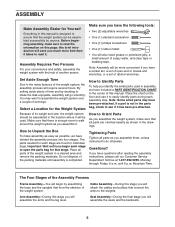
.... Set Aside Enough Time Due to do otherwise. Tightening Parts Tighten all parts of ratchet wrenches. Place the chart on this brief introduction will attach the cables and pulleys that there is completed. Assembly Requires Two Persons For your convenience and safety, assemble the weight system with the help you have been pre-attached. Before beginning assembly, make the task enjoyable, assembly will assemble the seats and...
.... Set Aside Enough Time Due to do otherwise. Tightening Parts Tighten all parts of ratchet wrenches. Place the chart on this brief introduction will attach the cables and pulleys that there is completed. Assembly Requires Two Persons For your convenience and safety, assemble the weight system with the help you have been pre-attached. Before beginning assembly, make the task enjoyable, assembly will assemble the seats and...
User Manual
Page 6
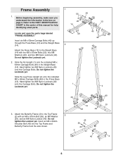
... and two M8 Nylon Locknuts (40). Hand tighten two M8 Nylon Locknuts (40) onto the Carriage Bolts. Frame Assembly 1. Attach the Butterfly Frame (3) to the PART IDENTIFICATION CHART in the Weight Base (14). Insert an M8 x 69mm Shoulder Bolt (43) into the Top Frame and Butterfly ...the Leg Press Upright (4) onto the indicated M8 x 63mm Carriage Bolts (49) in the box on page 5. Slide the Ab Upright (1) onto the indicated M8 x 63mm Carriage Bolts (49) in the center of this manual for help identifying small parts. 1 55 20 14 Locate and open the parts bags labeled "FRAME ASSEMBLY."...
... and two M8 Nylon Locknuts (40). Hand tighten two M8 Nylon Locknuts (40) onto the Carriage Bolts. Frame Assembly 1. Attach the Butterfly Frame (3) to the PART IDENTIFICATION CHART in the Weight Base (14). Insert an M8 x 69mm Shoulder Bolt (43) into the Top Frame and Butterfly ...the Leg Press Upright (4) onto the indicated M8 x 63mm Carriage Bolts (49) in the box on page 5. Slide the Ab Upright (1) onto the indicated M8 x 63mm Carriage Bolts (49) in the center of this manual for help identifying small parts. 1 55 20 14 Locate and open the parts bags labeled "FRAME ASSEMBLY."...
User Manual
Page 8
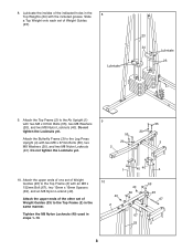
... Locknuts yet. 10. Lubricate 23 24 Lubricate 23 9. Lubricate the insides of Weight Guides (23). Attach the Top Frame (2) to the Leg Press Upright (4) with two M8 x 67mm Bolts (55), two M8 Washers (20), and two M8 Nylon Locknuts (40). Do not tighten the Locknuts yet. 55 20 55 Attach the Butterfly Frame (3) to the Ab Upright (1) 9 with two M8 x 67mm Bolts (55), two...
... Locknuts yet. 10. Lubricate 23 24 Lubricate 23 9. Lubricate the insides of Weight Guides (23). Attach the Top Frame (2) to the Leg Press Upright (4) with two M8 x 67mm Bolts (55), two M8 Washers (20), and two M8 Nylon Locknuts (40). Do not tighten the Locknuts yet. 55 20 55 Attach the Butterfly Frame (3) to the Ab Upright (1) 9 with two M8 x 67mm Bolts (55), two...
User Manual
Page 9
... be able to pivot easily. 8 9 53 42 72 Lubricate 13 71 14. Locate and open the parts bag labeled "ARM ASSEMBLY." Attach the Leg Press Bumper (53) to pivot easily. 14 High Hole Welded Spacers 42 9 12 52 Tube 13 Lubricate 54 the Leg Press Arm must be able to the Front 13 Seat Frame (8) with the indicated tube. the Press Frame must be a tight fit.
... be able to pivot easily. 8 9 53 42 72 Lubricate 13 71 14. Locate and open the parts bag labeled "ARM ASSEMBLY." Attach the Leg Press Bumper (53) to pivot easily. 14 High Hole Welded Spacers 42 9 12 52 Tube 13 Lubricate 54 the Leg Press Arm must be able to the Front 13 Seat Frame (8) with the indicated tube. the Press Frame must be a tight fit.
User Manual
Page 11
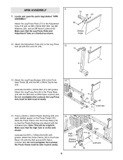
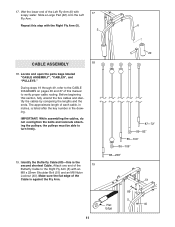
.... Locate and open the parts bags labeled "CABLE ASSEMBLY", "CABLES", and "PULLEYS." Wet the lower end of the Left Fly Arm (6) with an M8 x 22mm Shoulder Bolt (51) and an M8 Nylon Locknut (40). Repeat this manual to the CABLE DIAGRAMS on pages 26 and 27 of the Cable is the second shortest Cable. During steps 19 through 49, refer to verify proper cable routing. IMPORTANT: While assembling the cables...
.... Locate and open the parts bags labeled "CABLE ASSEMBLY", "CABLES", and "PULLEYS." Wet the lower end of the Left Fly Arm (6) with an M8 x 22mm Shoulder Bolt (51) and an M8 Nylon Locknut (40). Repeat this manual to the CABLE DIAGRAMS on pages 26 and 27 of the Cable is the second shortest Cable. During steps 19 through 49, refer to verify proper cable routing. IMPORTANT: While assembling the cables...
User Manual
Page 16
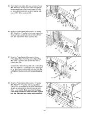
Attach the "V"-pulley to the lower bracket on the Front Seat Frame (8) with an M10 x 60mm Bolt (65) and an M10 Nylon Locknut (42). Hand tighten an M10 Nylon Locknut (42) onto the Bolt. Do not tighten the Locknut until completing step 39. 38. Wrap the Press Cable (88) around a 90mm Pulley (82). Wrap the Press Cable (88) around a "V"-pulley (81). Route the Press Cable (88) over a 90mm Pulley 35...
Attach the "V"-pulley to the lower bracket on the Front Seat Frame (8) with an M10 x 60mm Bolt (65) and an M10 Nylon Locknut (42). Hand tighten an M10 Nylon Locknut (42) onto the Bolt. Do not tighten the Locknut until completing step 39. 38. Wrap the Press Cable (88) around a 90mm Pulley (82). Wrap the Press Cable (88) around a "V"-pulley (81). Route the Press Cable (88) over a 90mm Pulley 35...
User Manual
Page 17
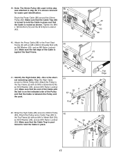
... posi- It is the shortest remaining cable. Route the Press Cable (88) around a 90mm Pulley (82). Identify the High Cable (85)-this step 39 was attached in place. 76 38 2 80 82 42 85 17 Make sure that the Cable Trap is routed as shown. Attach the Pulley to the Top Frame (2) with an M8 x 69mm Shoulder Bolt (43), 40 an M8 Washer...
... posi- It is the shortest remaining cable. Route the Press Cable (88) around a 90mm Pulley (82). Identify the High Cable (85)-this step 39 was attached in place. 76 38 2 80 82 42 85 17 Make sure that the Cable Trap is routed as shown. Attach the Pulley to the Top Frame (2) with an M8 x 69mm Shoulder Bolt (43), 40 an M8 Washer...
User Manual
Page 20
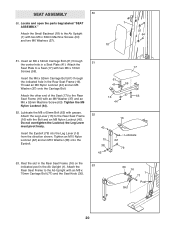
... post in the Rear Seat Frame (16). Do not overtighten the Locknut; Attach the 53 Rear Seat Frame to the Ab Upright (1) with an M8 x 70mm Carriage Bolt (77) and the Seat Knob (30). 30 16 1 77 Post Slot 20 Locate and open the parts bag labeled "SEAT ASSEMBLY." Attach the Seat Plate to the Rear Seat Frame (16) with two M6 x 16mm Screws (59). the Leg Lever must pivot...
... post in the Rear Seat Frame (16). Do not overtighten the Locknut; Attach the 53 Rear Seat Frame to the Ab Upright (1) with an M8 x 70mm Carriage Bolt (77) and the Seat Knob (30). 30 16 1 77 Post Slot 20 Locate and open the parts bag labeled "SEAT ASSEMBLY." Attach the Seat Plate to the Rear Seat Frame (16) with two M6 x 16mm Screws (59). the Leg Lever must pivot...
User Manual
Page 21
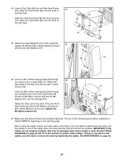
... use of the Seat (17) to the Leg Press 55 Upright (4) with an M6 Washer (37) and an M6 x 63mm Machine Screw (64). See the CABLE DIAGRAMS on page 26 and 27 of the Pad Tube. 29 28 29 15 55. Thread an M6 Nylon Locknut (44) with two M6 x 16mm Screws (59). Attach the other Pad Tube (28) into the Rear Seat...
... use of the Seat (17) to the Leg Press 55 Upright (4) with an M6 Washer (37) and an M6 x 63mm Machine Screw (64). See the CABLE DIAGRAMS on page 26 and 27 of the Pad Tube. 29 28 29 15 55. Thread an M6 Nylon Locknut (44) with two M6 x 16mm Screws (59). Attach the other Pad Tube (28) into the Rear Seat...
User Manual
Page 22
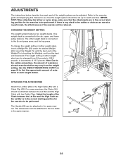
...- To change the weight setting of either weight stack can be adjusted. Note: Due to the cables and pulleys, the amount of resistance at each weight station. 93 90 93 ATTACHING THE ACCESSORIES Attach the Lat Bar (36) to the fly and press arms, and the leg press. For some exercises, the Chain (34) should be attached between the Lat Bar and the High Cable so the Lat Bar is connected to the High Cable (85...
...- To change the weight setting of either weight stack can be adjusted. Note: Due to the cables and pulleys, the amount of resistance at each weight station. 93 90 93 ATTACHING THE ACCESSORIES Attach the Lat Bar (36) to the fly and press arms, and the leg press. For some exercises, the Chain (34) should be attached between the Lat Bar and the High Cable so the Lat Bar is connected to the High Cable (85...
User Manual
Page 23
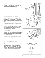
For some exercises, the Seat (17) must be attached to the front upright (see ATTACHING THE LEG LEVER TO THE LOW PULLEY STATION below). Lift the Rear Seat Frame off the Ab Upright (1). Align the holes in the Leg Press Arm (9) with the desired set the bracket on the Rear Seat Frame (16) onto the pins on the Adjustment Tube. 30 17 77 16 1 15 79 33 34 86...
For some exercises, the Seat (17) must be attached to the front upright (see ATTACHING THE LEG LEVER TO THE LOW PULLEY STATION below). Lift the Rear Seat Frame off the Ab Upright (1). Align the holes in the Leg Press Arm (9) with the desired set the bracket on the Rear Seat Frame (16) onto the pins on the Adjustment Tube. 30 17 77 16 1 15 79 33 34 86...
User Manual
Page 24
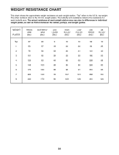
WEIGHT RESISTANCE CHART This chart shows the approximate weight resistance at each weight station may vary due to the 12.5 lb. top weight. The butterfly arm resistance listed is the resistance for each weight station. The actual resistance at each butterfly arm. weight plates. WEIGHT PLATES PRESS ARM (lbs.) BUTTERFLY ARM (lbs.) LEG LEVER (lbs.) HIGH PULLEY (lbs.) LOW PULLEY (lbs.) LEG PRESS (lbs.) AB PULLEY... other numbers refer to differences in individual weight plates, as well as friction between the cables, pulleys, and weight guides. "Top" refers to the 6.5 lb.
WEIGHT RESISTANCE CHART This chart shows the approximate weight resistance at each weight station may vary due to the 12.5 lb. top weight. The butterfly arm resistance listed is the resistance for each weight station. The actual resistance at each butterfly arm. weight plates. WEIGHT PLATES PRESS ARM (lbs.) BUTTERFLY ARM (lbs.) LEG LEVER (lbs.) HIGH PULLEY (lbs.) LOW PULLEY (lbs.) LEG PRESS (lbs.) AB PULLEY... other numbers refer to differences in individual weight plates, as well as friction between the cables, pulleys, and weight guides. "Top" refers to the 6.5 lb.
User Manual
Page 25
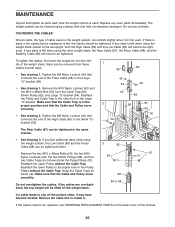
... when using the weight stack closest to the ab upright, both the High Cable (85) and the Low Cable (86) will need to the higher hole in the proper position and that the Cable and Pulley move smoothly. Do not overtighten the cables. Remove the cable and re-install it is first used . The weight system can be tightened. If there is slack in the cables before resistance...
... when using the weight stack closest to the ab upright, both the High Cable (85) and the Low Cable (86) will need to the higher hole in the proper position and that the Cable and Pulley move smoothly. Do not overtighten the cables. Remove the cable and re-install it is first used . The weight system can be tightened. If there is slack in the cables before resistance...
User Manual
Page 26
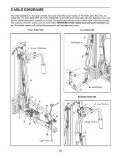
.... The starting and ending points of the High Cable (85), the Low Cable (86), the Rear Cable (87), the Press Cable (88), and the Butterfly Cable (89). Press Cable (88) Low Cable (86) 1-Long "U" Bracket 3 Ab Pulley-1 2 4 5 76 11 8 12 2 3 9 10 Leg Press-13 26 4-Low Pulley Butterfly Cable (89) 4 5-Left Fly Arm 2 1-Right Fly Arm 3 Use the diagrams to be sure that the cables have been assembled correctly. CABLE DIAGRAMS The cable diagrams on this...
.... The starting and ending points of the High Cable (85), the Low Cable (86), the Rear Cable (87), the Press Cable (88), and the Butterfly Cable (89). Press Cable (88) Low Cable (86) 1-Long "U" Bracket 3 Ab Pulley-1 2 4 5 76 11 8 12 2 3 9 10 Leg Press-13 26 4-Low Pulley Butterfly Cable (89) 4 5-Left Fly Arm 2 1-Right Fly Arm 3 Use the diagrams to be sure that the cables have been assembled correctly. CABLE DIAGRAMS The cable diagrams on this...
User Manual
Page 30
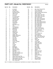
... 16 Cable Trap 81 3 "V"-pulley 82 21 90mm Pulley 83 1 Large Cable Trap 84 1 Large "U"-bracket 85 1 High Cable 86 1 Low Cable 87 1 Rear Cable 88 1 Press Cable 89 1 Butterfly Cable 90 16 Weight 91 2 M10 x 57mm Bolt 92 2 25mm Inner Cap 93 2 Weight Pin 94 2 Pulley Cover 95 1 M10 x 97mm Bolt 96 1 Handle # 1 User's Manual # 1 Exercise Guide # 2 Grease Packet Note: "#" indicates a non-illustrated part. WESY26331 R0904A Key No. Qty. PART LIST-Model No. Specifications are subject to change without...
... 16 Cable Trap 81 3 "V"-pulley 82 21 90mm Pulley 83 1 Large Cable Trap 84 1 Large "U"-bracket 85 1 High Cable 86 1 Low Cable 87 1 Rear Cable 88 1 Press Cable 89 1 Butterfly Cable 90 16 Weight 91 2 M10 x 57mm Bolt 92 2 25mm Inner Cap 93 2 Weight Pin 94 2 Pulley Cover 95 1 M10 x 97mm Bolt 96 1 Handle # 1 User's Manual # 1 Exercise Guide # 2 Grease Packet Note: "#" indicates a non-illustrated part. WESY26331 R0904A Key No. Qty. PART LIST-Model No. Specifications are subject to change without...
User Manual
Page 32
... to state. To help us assist you specific legal rights. The KEY NUMBER and DESCRIPTION of the part(s) (see the front cover of this product to be free from defects in connection with the use or performance of this manual) LIMITED WARRANTY ICON Health & Fitness, Inc. (ICON), warrants this manual) 4. ICON's obligation under normal use , costs of removal or installation or other warranties and any and all other consequential damages of...
... to state. To help us assist you specific legal rights. The KEY NUMBER and DESCRIPTION of the part(s) (see the front cover of this product to be free from defects in connection with the use or performance of this manual) LIMITED WARRANTY ICON Health & Fitness, Inc. (ICON), warrants this manual) 4. ICON's obligation under normal use , costs of removal or installation or other warranties and any and all other consequential damages of...


