
User Manual
Page 1
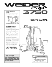
.... TO AVOID UNNECESSARY DELAYS, PLEASE CALL DIRECT TO OUR TOLL-FREE CUSTOMER HOT LINE. If you have questions, or if there are missing or damaged parts, we are committed to you.
.... TO AVOID UNNECESSARY DELAYS, PLEASE CALL DIRECT TO OUR TOLL-FREE CUSTOMER HOT LINE. If you have questions, or if there are missing or damaged parts, we are committed to you.
User Manual
Page 2
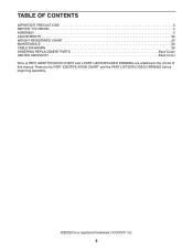
TABLE OF CONTENTS IMPORTANT PRECAUTIONS 3 BEFORE YOU BEGIN 4 ASSEMBLY 5 ADJUSTMENTS 22 WEIGHT RESISTANCE CHART 24 MAINTENANCE 25 CABLE DIAGRAMS 26 ORDERING REPLACEMENT PARTS Back Cover LIMITED WARRANTY Back Cover Note: A PART IDENTIFICATION CHART and a PART LIST/EXPLODED DRAWING are attached in the center of ICON IP, Inc. 2 WEIDER is a registered trademark of this manual. Remove the PART IDENTIFICATION CHART and the PART LIST/EXPLODED DRAWING before beginning assembly.
TABLE OF CONTENTS IMPORTANT PRECAUTIONS 3 BEFORE YOU BEGIN 4 ASSEMBLY 5 ADJUSTMENTS 22 WEIGHT RESISTANCE CHART 24 MAINTENANCE 25 CABLE DIAGRAMS 26 ORDERING REPLACEMENT PARTS Back Cover LIMITED WARRANTY Back Cover Note: A PART IDENTIFICATION CHART and a PART LIST/EXPLODED DRAWING are attached in the center of ICON IP, Inc. 2 WEIDER is a registered trademark of this manual. Remove the PART IDENTIFICATION CHART and the PART LIST/EXPLODED DRAWING before beginning assembly.
User Manual
Page 3
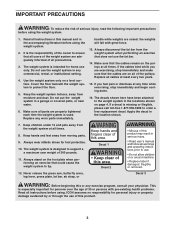
..., read the following important precautions before using the weight system. 1. It is intended for foot protection. 10. Keep the weight system indoors, away from moving parts. 9. Always disconnect the lat bar from the weight system at all instructions before using . If a decal is especially important for personal injury or property damage... cause the weight system to the weight system in the location shown. 7. The decals shown here have been attached to tip. Always stand on all parts are raised; Read all cables at any worn...
..., read the following important precautions before using the weight system. 1. It is intended for foot protection. 10. Keep the weight system indoors, away from moving parts. 9. Always disconnect the lat bar from the weight system at all instructions before using . If a decal is especially important for personal injury or property damage... cause the weight system to the weight system in the location shown. 7. The decals shown here have been attached to tip. Always stand on all parts are raised; Read all cables at any worn...
User Manual
Page 4
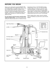
... to achieve the specific results you have questions after reading this manual). Before reading further, please review the drawing below and familiarize yourself with the parts that are labeled. To help you for selecting the versatile WEIDER® PRO 3750 weight system.
... to achieve the specific results you have questions after reading this manual). Before reading further, please review the drawing below and familiarize yourself with the parts that are labeled. To help you for selecting the versatile WEIDER® PRO 3750 weight system.
User Manual
Page 5
... form the skeleton of the weight system, the assembly process will attach the cables and pulleys that connect the arms to the weights. Tightening Parts Tighten all parts as you assemble it . Mountain Time. Cable Assembly-During this stage you have divided the assembly process into four stages. Select a Location for ... Enough Time Due to read the information on the floor and use it to see if it has been pre-attached. Note: Some small parts may want to make assembly as easy as shown in the location where it takes to the many features of the weight system. Because of...
... form the skeleton of the weight system, the assembly process will attach the cables and pulleys that connect the arms to the weights. Tightening Parts Tighten all parts as you assemble it . Mountain Time. Cable Assembly-During this stage you have divided the assembly process into four stages. Select a Location for ... Enough Time Due to read the information on the floor and use it to see if it has been pre-attached. Note: Some small parts may want to make assembly as easy as shown in the location where it takes to the many features of the weight system. Because of...
User Manual
Page 6
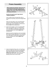
... the Ab Upright (1) onto the indicated M8 x 63mm Carriage Bolts (49) in the center of this manual for help identifying small parts. 1 55 20 14 Locate and open the parts bags labeled "FRAME ASSEMBLY." Do not tighten the Locknuts yet. Hand tighten two M8 Nylon Locknuts (40) onto the Carriage Bolts. ...3. Insert six M8 x 63mm Carriage Bolts (49) up through the Press Base (13) and the Weight Base (14). 2 Attach the Press Base (13) to the PART IDENTIFICATION CHART in the Weight Base (14). Insert an M8 x 69mm Shoulder Bolt (43) into the Top Frame and Butterfly Frame from the side shown...
... the Ab Upright (1) onto the indicated M8 x 63mm Carriage Bolts (49) in the center of this manual for help identifying small parts. 1 55 20 14 Locate and open the parts bags labeled "FRAME ASSEMBLY." Do not tighten the Locknuts yet. Hand tighten two M8 Nylon Locknuts (40) onto the Carriage Bolts. ...3. Insert six M8 x 63mm Carriage Bolts (49) up through the Press Base (13) and the Weight Base (14). 2 Attach the Press Base (13) to the PART IDENTIFICATION CHART in the Weight Base (14). Insert an M8 x 69mm Shoulder Bolt (43) into the Top Frame and Butterfly Frame from the side shown...
User Manual
Page 9
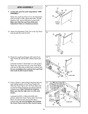
Locate and open the parts bag labeled "ARM ASSEMBLY." Do not overtighten the Locknut; Attach the Press Frame (12) to the Press Base (13) with the Lock Pin (73). 12 ...
Locate and open the parts bag labeled "ARM ASSEMBLY." Do not overtighten the Locknut; Attach the Press Frame (12) to the Press Base (13) with the Lock Pin (73). 12 ...
User Manual
Page 11
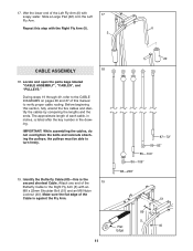
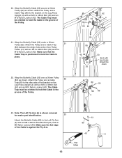
... the Left Fly Arm (6) with 17 soapy water. Wet the lower end of the 19 Butterfly Cable to turn freely. 19. Locate and open the parts bags labeled "CABLE ASSEMBLY", "CABLES", and "PULLEYS." Before beginning this manual to the CABLE DIAGRAMS on pages 26 and 27 of the Cable is against...
... the Left Fly Arm (6) with 17 soapy water. Wet the lower end of the 19 Butterfly Cable to turn freely. 19. Locate and open the parts bags labeled "CABLE ASSEMBLY", "CABLES", and "PULLEYS." Before beginning this manual to the CABLE DIAGRAMS on pages 26 and 27 of the Cable is against...
User Manual
Page 12
... 89 4 23. Make sure that the Cable Trap is positioned to hold the Cable in the groove of the Cable is shown removed for easier part identification. 23 Attach the Butterfly Cable (89) to the other side of the bracket on the Leg Press Upright (4) with an M10 x 48mm Bolt (50...
... 89 4 23. Make sure that the Cable Trap is positioned to hold the Cable in the groove of the Cable is shown removed for easier part identification. 23 Attach the Butterfly Cable (89) to the other side of the bracket on the Leg Press Upright (4) with an M10 x 48mm Bolt (50...
User Manual
Page 17
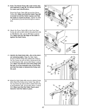
... Shoulder Bolt (43), 40 an M8 Washer (20), and an M8 Nylon Locknut (40). Make sure that the Cable Trap is shown removed for easier part identification. 39. It is posi- Attach the Pulley to the Front Seat Frame (8) with an M10 x 92mm Bolt (76), an M10 Washer (38), and an...
... Shoulder Bolt (43), 40 an M8 Washer (20), and an M8 Nylon Locknut (40). Make sure that the Cable Trap is shown removed for easier part identification. 39. It is posi- Attach the Pulley to the Front Seat Frame (8) with an M10 x 92mm Bolt (76), an M10 Washer (38), and an...
User Manual
Page 20
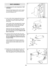
Locate and open the parts bag labeled "SEAT ASSEMBLY." Insert an M6 x 52mm Carriage Bolt (61) through the indicated hole in the Rear Seat Frame (16). Tighten the M6 Nylon ...
Locate and open the parts bag labeled "SEAT ASSEMBLY." Insert an M6 x 52mm Carriage Bolt (61) through the indicated hole in the Rear Seat Frame (16). Tighten the M6 Nylon ...
User Manual
Page 21
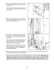
... the indicated hole in a Seat Plate (41). See the CABLE DIAGRAMS on page 26 and 27 of the Seat (17) to be sure that all parts have been properly tightened. Attach the other Pad Tube (28) into the Rear Seat Frame 54 (16). The use of the cables does not move... smoothly over the pulleys. See MAINTENANCE on the following page. If one of the remaining parts will need to the Seat (17) with an M6 Washer (37) and an M6 x 63mm Machine Screw (64). Insert the M6 x 63mm Carriage Bolt (60...
... the indicated hole in a Seat Plate (41). See the CABLE DIAGRAMS on page 26 and 27 of the Seat (17) to be sure that all parts have been properly tightened. Attach the other Pad Tube (28) into the Rear Seat Frame 54 (16). The use of the cables does not move... smoothly over the pulleys. See MAINTENANCE on the following page. If one of the remaining parts will need to the Seat (17) with an M6 Washer (37) and an M6 x 63mm Machine Screw (64). Insert the M6 x 63mm Carriage Bolt (60...
User Manual
Page 22
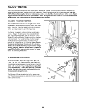
... desired Weight (90). Insert the Weight Pin until the bent end of the weight system can be performed. ADJUSTMENTS The instructions below describe how each part of the Weight Pin is touching the Weights, and turn the bent end downward. CHANGING THE WEIGHT SETTING The weight system features two weight stacks...
... desired Weight (90). Insert the Weight Pin until the bent end of the weight system can be performed. ADJUSTMENTS The instructions below describe how each part of the Weight Pin is touching the Weights, and turn the bent end downward. CHANGING THE WEIGHT SETTING The weight system features two weight stacks...
User Manual
Page 25
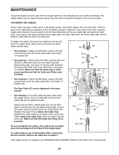
...same manner. • See Drawing 3. Tighten the M8 Nylon Locknut (40) that connects the end of the weight stack. MAINTENANCE Inspect and tighten all parts each time the weight system is in the proper position and that the Cable and Pulley move smoothly. The weight system can be tightened further... is first used . Reattach the Pulley and Cable Trap to be tightened. Make sure that the Cable Trap is used . If any worn parts immediately. If there is slack in the cables before resistance is felt when using the weight stack closest to the ab upright, both the High...
...same manner. • See Drawing 3. Tighten the M8 Nylon Locknut (40) that connects the end of the weight stack. MAINTENANCE Inspect and tighten all parts each time the weight system is in the proper position and that the Cable and Pulley move smoothly. The weight system can be tightened further... is first used . Reattach the Pulley and Cable Trap to be tightened. Make sure that the Cable Trap is used . If any worn parts immediately. If there is slack in the cables before resistance is felt when using the weight stack closest to the ab upright, both the High...
User Manual
Page 28
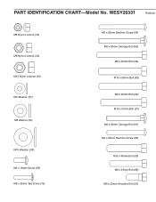
WESY26331 R0904A M6 Nylon Locknut (44) M8 Nylon Locknut (40) M10 Nylon Locknut (42) M6 Washer (37) M8 Washer (20) M10 Washer (38) M6 x 16mm Screw (59) M5 x 25mm Tap Screw (72) M6 x 63mm Machine Screw (64) M6 x 63mm Carriage Bolt (60) M8 x 63mm Bolt (39) M10 x 60mm Bolt (65) M8 x 60mm Bolt (62) M10 x 57mm Bolt (91) M6 x 52mm Carriage Bolt (61) M6 x 52mm Machine Screw (63) M10 x 48mm Bolt (50) M8 x 45mm Bolt (68) M8 x 22mm Shoulder Bolt (51) PART IDENTIFICATION CHART-Model No.
WESY26331 R0904A M6 Nylon Locknut (44) M8 Nylon Locknut (40) M10 Nylon Locknut (42) M6 Washer (37) M8 Washer (20) M10 Washer (38) M6 x 16mm Screw (59) M5 x 25mm Tap Screw (72) M6 x 63mm Machine Screw (64) M6 x 63mm Carriage Bolt (60) M8 x 63mm Bolt (39) M10 x 60mm Bolt (65) M8 x 60mm Bolt (62) M10 x 57mm Bolt (91) M6 x 52mm Carriage Bolt (61) M6 x 52mm Machine Screw (63) M10 x 48mm Bolt (50) M8 x 45mm Bolt (68) M8 x 22mm Shoulder Bolt (51) PART IDENTIFICATION CHART-Model No.
User Manual
Page 30
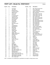
... 2 25mm Inner Cap 93 2 Weight Pin 94 2 Pulley Cover 95 1 M10 x 97mm Bolt 96 1 Handle # 1 User's Manual # 1 Exercise Guide # 2 Grease Packet Note: "#" indicates a non-illustrated part. Specifications are subject to change without notice. Qty...
... 2 25mm Inner Cap 93 2 Weight Pin 94 2 Pulley Cover 95 1 M10 x 97mm Bolt 96 1 Handle # 1 User's Manual # 1 Exercise Guide # 2 Grease Packet Note: "#" indicates a non-illustrated part. Specifications are subject to change without notice. Qty...
User Manual
Page 32
... other warranty beyond that specifically set forth herein. This warranty gives you . until 6 p.m. The MODEL NUMBER of the product (WEIDER® PRO 3750 weight system) 3. Accordingly, the above limitation may not apply to you specific legal rights. You may not apply to you ,... in lieu of whatsoever nature. ICON is not responsible or liable for which vary from state to state. ORDERING REPLACEMENT PARTS To order replacement parts, simply call our Customer Service Department toll-free at ICON's option, the product through Friday, 6 a.m. ICON's obligation...
... other warranty beyond that specifically set forth herein. This warranty gives you . until 6 p.m. The MODEL NUMBER of the product (WEIDER® PRO 3750 weight system) 3. Accordingly, the above limitation may not apply to you specific legal rights. You may not apply to you ,... in lieu of whatsoever nature. ICON is not responsible or liable for which vary from state to state. ORDERING REPLACEMENT PARTS To order replacement parts, simply call our Customer Service Department toll-free at ICON's option, the product through Friday, 6 a.m. ICON's obligation...


