
English Manual
Page 1
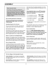
Serial Number Decal (Under Seat) QUESTIONS? If you have questions, or if a part is damaged or missing, PLEASE CONTACT OUR CUSTOMER SERVICE DEPARTMENT DIRECTLY. Visit our website at www.weiderfitness.com new products, prizes, fitness tips, and much more! As a manufacturer, we are committed to providing complete customer satisfaction. MST ON THE WEB: www.weiderservice.com USER'S MANUAL CAUTION Read all precautions and instructions in the space above for future reference. Model No. WESY3906.1 Serial No. Write the serial number in this manual before using this manual for ...
Serial Number Decal (Under Seat) QUESTIONS? If you have questions, or if a part is damaged or missing, PLEASE CONTACT OUR CUSTOMER SERVICE DEPARTMENT DIRECTLY. Visit our website at www.weiderfitness.com new products, prizes, fitness tips, and much more! As a manufacturer, we are committed to providing complete customer satisfaction. MST ON THE WEB: www.weiderservice.com USER'S MANUAL CAUTION Read all precautions and instructions in the space above for future reference. Model No. WESY3906.1 Serial No. Write the serial number in this manual before using this manual for ...
English Manual
Page 2
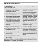
... PARTS Back Cover LIMITED WARRANTY Back Cover WARNING DECAL PLACEMENT The decals shown here have been placed on the front cover of ICON IP, Inc. 2 WEIDER is missing or illegible, call the toll-free telephone number on the weight system. If a decal is a registered trademark of this manual and order a free...
... PARTS Back Cover LIMITED WARRANTY Back Cover WARNING DECAL PLACEMENT The decals shown here have been placed on the front cover of ICON IP, Inc. 2 WEIDER is missing or illegible, call the toll-free telephone number on the weight system. If a decal is a registered trademark of this manual and order a free...
English Manual
Page 3
It is especially important for home use the weight system in this manual. 2. Do not use only. Place the weight system on page 26). 8. Replace all parts regular- 14. Inspect and properly tighten all cables at all warnings on the pulleys. This is the responsibility of the owner to ensure that the cables are adequately informed of all precautions. 3. Keep the weight system indoors, away from moving parts. 15. The weight system is designed to mount, dismount, and use the lat bar. 5. The weights will fall with the included weight. Replace any commercial, ...
It is especially important for home use the weight system in this manual. 2. Do not use only. Place the weight system on page 26). 8. Replace all parts regular- 14. Inspect and properly tighten all cables at all warnings on the pulleys. This is the responsibility of the owner to ensure that the cables are adequately informed of all precautions. 3. Keep the weight system indoors, away from moving parts. 15. The weight system is designed to mount, dismount, and use the lat bar. 5. The weights will fall with the included weight. Replace any commercial, ...
English Manual
Page 4
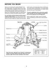
... the front cover of this manual. To help you to achieve the specific results you want. To avoid a registration fee for selecting the versatile WEIDER® Club 4870 weight system. they do not correspond to tone your body, build dramatic muscle size and strength, or improve your cardiovascular system, the weight system will...
... the front cover of this manual. To help you to achieve the specific results you want. To avoid a registration fee for selecting the versatile WEIDER® Club 4870 weight system. they do not correspond to tone your body, build dramatic muscle size and strength, or improve your cardiovascular system, the weight system will...
English Manual
Page 5
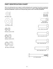
PART IDENTIFICATION CHART Refer to see if it has been preattached. Note: Some small parts may have been preattached. M6 Washer (90) M4 x 16mm Self-tapping Screw (100) M10 Washer (108) M6 Nylon Locknut (103) M8 Nylon Locknut (101) M10 Nylon Locknut (84) M8 x 25mm Shoulder Bolt (92) M10 x 35mm Screw (89) M10 x 40mm Bolt (104) M10 x 45mm Bolt (95) M10 x 50mm Bolt (105) 2 1/4" Bolt Set (86) 5 The number in parentheses by each drawing is not in assembly. If a part is the key number of the part, from the PART LIST on page 6 to identify small parts used in the parts bag, check to ...
PART IDENTIFICATION CHART Refer to see if it has been preattached. Note: Some small parts may have been preattached. M6 Washer (90) M4 x 16mm Self-tapping Screw (100) M10 Washer (108) M6 Nylon Locknut (103) M8 Nylon Locknut (101) M10 Nylon Locknut (84) M8 x 25mm Shoulder Bolt (92) M10 x 35mm Screw (89) M10 x 40mm Bolt (104) M10 x 45mm Bolt (95) M10 x 50mm Bolt (105) 2 1/4" Bolt Set (86) 5 The number in parentheses by each drawing is not in assembly. If a part is the key number of the part, from the PART LIST on page 6 to identify small parts used in the parts bag, check to ...

English Manual
Page 6
"V"-pulley (44) (Not shown to scale) Pulley (43) (Not shown to scale) M10 x 65mm Bolt (87) M10 x 70mm Bolt (57) M10 x 75mm Bolt (96) M10 x 80mm Carriage Bolt (88) M6 x 80mm Screw (98) M10 x 90mm Bolt (102) M10 x 95mm Bolt (107) M10 x 100mm Bolt (85) M10 x 120mm Bolt (97) M10 x 130mm Bolt (106) M10 x 150mm Bolt (94) 6
"V"-pulley (44) (Not shown to scale) Pulley (43) (Not shown to scale) M10 x 65mm Bolt (87) M10 x 70mm Bolt (57) M10 x 75mm Bolt (96) M10 x 80mm Carriage Bolt (88) M6 x 80mm Screw (98) M10 x 90mm Bolt (102) M10 x 95mm Bolt (107) M10 x 100mm Bolt (85) M10 x 120mm Bolt (97) M10 x 130mm Bolt (106) M10 x 150mm Bolt (94) 6
English Manual
Page 7
Assembly Requires Two Persons For your convenience and safety, assemble the weight system with the help of the weight system. area and remove the packing materials. Make sure that there is enough clearance to open -end or closed-end wrenches, or a set of the Assembly Process Frame Assembly-You will be assembled successfully by almost anyone. Important: Wait until assembly is completed. Tightening Parts Tighten all parts as you will assemble the arms and the moving parts. Questions? Select a Location for that connect the arms to identify the small parts used . If ...
Assembly Requires Two Persons For your convenience and safety, assemble the weight system with the help of the weight system. area and remove the packing materials. Make sure that there is enough clearance to open -end or closed-end wrenches, or a set of the Assembly Process Frame Assembly-You will be assembled successfully by almost anyone. Important: Wait until assembly is completed. Tightening Parts Tighten all parts as you will assemble the arms and the moving parts. Questions? Select a Location for that connect the arms to identify the small parts used . If ...
English Manual
Page 8
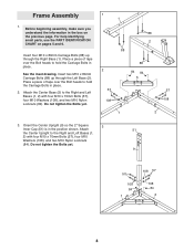
Insert four M10 x 80mm Carriage Bolts (88) up through the Right Base (1). Insert two M10 x 80mm Carriage Bolts (88) up through the Left Base (2). Orient the Center Upright (9) so the 2" Square 3 Inner Cap (51) is in place. 2. Before beginning assembly, make sure you understand the information in place. For help identifying small parts, use the PART IDENTIFICATION CHART on the previous page. Place a piece of tape over the Bolt heads to hold the Carriage Bolts in the box on pages 5 and 6. See the inset drawing. Do not tighten the Bolts yet. 1 1 88 2 88 2 57 ...
Insert four M10 x 80mm Carriage Bolts (88) up through the Right Base (1). Insert two M10 x 80mm Carriage Bolts (88) up through the Left Base (2). Orient the Center Upright (9) so the 2" Square 3 Inner Cap (51) is in place. 2. Before beginning assembly, make sure you understand the information in place. For help identifying small parts, use the PART IDENTIFICATION CHART on the previous page. Place a piece of tape over the Bolt heads to hold the Carriage Bolts in the box on pages 5 and 6. See the inset drawing. Do not tighten the Bolts yet. 1 1 88 2 88 2 57 ...

English Manual
Page 9
Attach the Right Seat Upright (11) to the Right Base (1) 4 with two M10 x 90mm Bolts (102) and two M10 Nylon Locknuts (84). Do not tighten the Nylon Locknuts yet. 7 102 84 1 5. Attach the Right Upright (7) to the Right 5 Base (1) with the indicated M10 x 80mm Carriage Bolts (88) and two M10 Nylon Locknuts (84). 10 84 84 1 88 9 Attach the Curl Post Upright (10) to the Right 6 Base (1) with the indicated M10 x 80mm Carriage Bolts (88) and two M10 Nylon Locknuts (84). 11 84 84 1 88 6. 4.
Attach the Right Seat Upright (11) to the Right Base (1) 4 with two M10 x 90mm Bolts (102) and two M10 Nylon Locknuts (84). Do not tighten the Nylon Locknuts yet. 7 102 84 1 5. Attach the Right Upright (7) to the Right 5 Base (1) with the indicated M10 x 80mm Carriage Bolts (88) and two M10 Nylon Locknuts (84). 10 84 84 1 88 9 Attach the Curl Post Upright (10) to the Right 6 Base (1) with the indicated M10 x 80mm Carriage Bolts (88) and two M10 Nylon Locknuts (84). 11 84 84 1 88 6. 4.

English Manual
Page 10
Attach the Right Top Frame (3) to the Center 9 Upright (9) with two M10 x 90mm Bolts (102) and two M10 Nylon Locknuts (84). Attach the Right Top Frame (3) to the Right Upright (7) with two M10 x 70mm Bolts (57), two M10 Washers (108), and an M10 Nylon Locknut (84). Do not tighten the Bolts yet. Do not tighten the Nylon Locknuts yet. 3 84 7 84 57 108 9 102 10 Do not tighten the Nylon Locknuts yet. 8 102 84 8. Attach the Left Seat Upright (14) to the Left Base (2) 7 with the indicated M10 x 80mm Carriage Bolts (88) and two M10 Nylon Locknuts (84). 2 14 84 84 2 ...
Attach the Right Top Frame (3) to the Center 9 Upright (9) with two M10 x 90mm Bolts (102) and two M10 Nylon Locknuts (84). Attach the Right Top Frame (3) to the Right Upright (7) with two M10 x 70mm Bolts (57), two M10 Washers (108), and an M10 Nylon Locknut (84). Do not tighten the Bolts yet. Do not tighten the Nylon Locknuts yet. 3 84 7 84 57 108 9 102 10 Do not tighten the Nylon Locknuts yet. 8 102 84 8. Attach the Left Seat Upright (14) to the Left Base (2) 7 with the indicated M10 x 80mm Carriage Bolts (88) and two M10 Nylon Locknuts (84). 2 14 84 84 2 ...

English Manual
Page 11
Do not tighten the Bolts yet. Orient a Weight Guide (30) with the indicated hole closer to the Left Upright (8) with two M10 x 90mm Bolts (102) and two M10 Nylon Locknuts (84). Slide a Weight Bumper (66) onto the Weight Guide. Attach the Left Top Frame (4) to the bottom. Attach the Butterfly Frame (24) to the Center Base (5) in step 2. 89 12 7 30 30 Hole 66 84 108 68 5 108 87 11 Attach the other Weight Guide (30) to the Right Top 11 Frame (3) with two M10 x 35mm Screws (89). Do not tighten the Nylon Locknuts yet. 10 57 108 4 84 9 102 84 8 11. Do not ...
Do not tighten the Bolts yet. Orient a Weight Guide (30) with the indicated hole closer to the Left Upright (8) with two M10 x 90mm Bolts (102) and two M10 Nylon Locknuts (84). Slide a Weight Bumper (66) onto the Weight Guide. Attach the Left Top Frame (4) to the bottom. Attach the Butterfly Frame (24) to the Center Base (5) in step 2. 89 12 7 30 30 Hole 66 84 108 68 5 108 87 11 Attach the other Weight Guide (30) to the Right Top 11 Frame (3) with two M10 x 35mm Screws (89). Do not tighten the Nylon Locknuts yet. 10 57 108 4 84 9 102 84 8 11. Do not ...
English Manual
Page 12
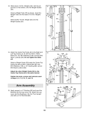
Weights (34), with four M10 x 70mm Bolts (57), four M10 Washers (108), and two M10 Nylon Locknuts (84). Attach the Center Top Frame (6) to a 2" Bushing (63) and insert the Bushing into the stack of 12.5-lb. Tighten the bolts, screws and locknuts used in the same manner. Slide another 12.5-lb. Attach a Weight Guide (30) inside the Center Top Frame (6) with a 2 1/4" Bolt Set (86). 86 63 15 Grease 86 10 12 Orient a Weight Tube (75) as shown. Insert the Weight Tube into the Leg Lever (15). Weights (34). Weight (34) onto the Weight Guides (30). 34 30 30 75 34 Pin Groove...
Weights (34), with four M10 x 70mm Bolts (57), four M10 Washers (108), and two M10 Nylon Locknuts (84). Attach the Center Top Frame (6) to a 2" Bushing (63) and insert the Bushing into the stack of 12.5-lb. Tighten the bolts, screws and locknuts used in the same manner. Slide another 12.5-lb. Attach a Weight Guide (30) inside the Center Top Frame (6) with a 2 1/4" Bolt Set (86). 86 63 15 Grease 86 10 12 Orient a Weight Tube (75) as shown. Insert the Weight Tube into the Leg Lever (15). Weights (34). Weight (34) onto the Weight Guides (30). 34 30 30 75 34 Pin Groove...
English Manual
Page 13
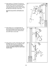
Next, insert the 3" Bushing into the Military Press Frame (20). Attach the Military Press Frame inside the Left Upright (8) with the Left Butterfly Arm (22). 61 Grease 84 23 61 71 Grease 24 22 85 91 17. Apply grease to the Butterfly Frame (24) with the Bolt and an M10 Nylon Locknut (84). Attach the Butterfly Arm to an M10 x 45mm Bolt (95). Do not overtighten the Nylon Locknut; Apply grease to pivot easily. 87 84 20 64 8 Grease 20 Grease 95 84 21 13 16. Apply grease to the Military Press Frame (20) with an M10 x 100mm Bolt (85) and an M10 Nylon ...
Next, insert the 3" Bushing into the Military Press Frame (20). Attach the Military Press Frame inside the Left Upright (8) with the Left Butterfly Arm (22). 61 Grease 84 23 61 71 Grease 24 22 85 91 17. Apply grease to the Butterfly Frame (24) with the Bolt and an M10 Nylon Locknut (84). Attach the Butterfly Arm to an M10 x 45mm Bolt (95). Do not overtighten the Nylon Locknut; Apply grease to pivot easily. 87 84 20 64 8 Grease 20 Grease 95 84 21 13 16. Apply grease to the Military Press Frame (20) with an M10 x 100mm Bolt (85) and an M10 Nylon ...

English Manual
Page 14
Attach the Left Press Arm (25) to pivot easily. the Press Arm Handle must be able to the Press Frame (13) in the same manner. 2 102 65 Grease 57 26 25 84 13 21. 19. Attach the Right Press Arm (26) to the Right Press Arm (26) with two M10 x 70mm Bolts (57) and two M10 Nylon Locknuts (84). Do not overtighten the Nylon Locknut; Attach a Press Arm Handle (27) to the Press 20 Frame (13) with the Bolt and an M10 Nylon Locknut (84). Apply grease to the Left Base (2) with an M10 x 90mm Bolt (102) and an M10 Nylon Locknut (84). 13 84 20. Repeat this step with the ...
Attach the Left Press Arm (25) to pivot easily. the Press Arm Handle must be able to the Press Frame (13) in the same manner. 2 102 65 Grease 57 26 25 84 13 21. 19. Attach the Right Press Arm (26) to the Right Press Arm (26) with two M10 x 70mm Bolts (57) and two M10 Nylon Locknuts (84). Do not overtighten the Nylon Locknut; Attach a Press Arm Handle (27) to the Press 20 Frame (13) with the Bolt and an M10 Nylon Locknut (84). Apply grease to the Left Base (2) with an M10 x 90mm Bolt (102) and an M10 Nylon Locknut (84). 13 84 20. Repeat this step with the ...
English Manual
Page 15
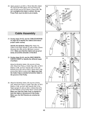
Attach 23 the Leg Press Plate (29) to the Left Butterfly Arm (22) with the Bolt and an M10 Nylon Locknut (84). Identify the Butterfly Cable (73). Attach the Pulley, a Cable Trap (48), an M10 Washer (108), and two Guards (45) to the Leg Press (12) with an M10 x 50mm Bolt (105) and an M10 Nylon Locknut (84). Wrap the Butterfly Cable (73) around a Pulley (43). 23. Wrap the Butterfly Cable (73) around a Pulley 26 (43). Cable Assembly 24 24. During steps 25-52, see the CABLE DIAGRAM on page 28 to pivot easily. Make sure that the Cable Trap is oriented to the Right ...
Attach 23 the Leg Press Plate (29) to the Left Butterfly Arm (22) with the Bolt and an M10 Nylon Locknut (84). Identify the Butterfly Cable (73). Attach the Pulley, a Cable Trap (48), an M10 Washer (108), and two Guards (45) to the Leg Press (12) with an M10 x 50mm Bolt (105) and an M10 Nylon Locknut (84). Wrap the Butterfly Cable (73) around a Pulley (43). 23. Wrap the Butterfly Cable (73) around a Pulley 26 (43). Cable Assembly 24 24. During steps 25-52, see the CABLE DIAGRAM on page 28 to pivot easily. Make sure that the Cable Trap is oriented to the Right ...
English Manual
Page 16
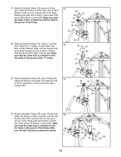
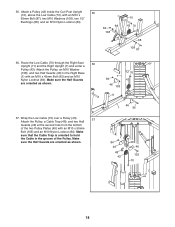
Wrap the Butterfly Cable (73) under a Pulley (43). 30 Attach the Pulley, a Cable Trap (48), and two Half Guards (46) at the second hole from the top of the Pulley. Make sure that the Cable Trap is oriented to the Right Upright (7) with an M10 x 40mm Bolt (104) and an M10 Nylon Locknut (84). 105 84 44 73 45 45 83 108 7 94 84 43 73 3 104 30. Attach the "V"-pulley, a Long Cable Trap (83), an M10 Washer (108), and two Guards (45) to hold the Cable in the groove of the Pulley. 27 84 45 48 43 73 108 45 23 28. Wrap the Butterfly Cable (73) around a Pulley (43). Wrap ...
Wrap the Butterfly Cable (73) under a Pulley (43). 30 Attach the Pulley, a Cable Trap (48), and two Half Guards (46) at the second hole from the top of the Pulley. Make sure that the Cable Trap is oriented to the Right Upright (7) with an M10 x 40mm Bolt (104) and an M10 Nylon Locknut (84). 105 84 44 73 45 45 83 108 7 94 84 43 73 3 104 30. Attach the "V"-pulley, a Long Cable Trap (83), an M10 Washer (108), and two Guards (45) to hold the Cable in the groove of the Pulley. 27 84 45 48 43 73 108 45 23 28. Wrap the Butterfly Cable (73) around a Pulley (43). Wrap ...
English Manual
Page 17
Identify the Low Cable (70). 31. Attach the Butterfly Cable (73) and a Weight Cap 33 (67) to the indicated Weight Tube (75) with an M10 x 45mm Bolt (95) and an M10 Nylon Locknut (84). 84 3 73 95 43 32. Route the Cable 34 through the Leg Lever (15) and the Curl Post Upright (10). Wrap the Butterfly Cable (73) over a Pulley (43). 32 Attach the Pulley to the Right Top Frame (3) with an M10 x 50mm Bolt (105) and an M10 Nylon Locknut (84). 73 84 67 75 105 34. Wrap the Butterfly Cable (73) over a Pulley (43). 31 Attach the Pulley to the Center Top Frame (6) with ...
Identify the Low Cable (70). 31. Attach the Butterfly Cable (73) and a Weight Cap 33 (67) to the indicated Weight Tube (75) with an M10 x 45mm Bolt (95) and an M10 Nylon Locknut (84). 84 3 73 95 43 32. Route the Cable 34 through the Leg Lever (15) and the Curl Post Upright (10). Wrap the Butterfly Cable (73) over a Pulley (43). 32 Attach the Pulley to the Right Top Frame (3) with an M10 x 50mm Bolt (105) and an M10 Nylon Locknut (84). 73 84 67 75 105 34. Wrap the Butterfly Cable (73) over a Pulley (43). 31 Attach the Pulley to the Center Top Frame (6) with ...
English Manual
Page 18
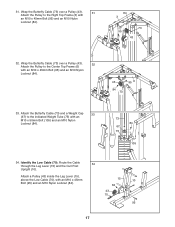
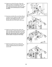
35. Make sure the Half Guards are oriented as shown. 7 84 46 108 70 43 11 46 1 95 84 46 48 43 49 46 105 70 18 Wrap the Low Cable (70) over a Pulley (43). 37 Attach the Pulley, a Cable Trap (48), and two Half Guards (46) at the second hole from the bottom of the Pulley. Attach the Pulley, an M10 Washer (108), and two Half Guards (46) to hold the Cable in the groove of the two Pulley Plates (49) with an M10 x 50mm Bolt (105) and an M10 Nylon Locknut (84). Make sure that the Cable Trap is oriented to the Right Base (1) with an M10 x 65mm Bolt (87), two M10 Washers...
35. Make sure the Half Guards are oriented as shown. 7 84 46 108 70 43 11 46 1 95 84 46 48 43 49 46 105 70 18 Wrap the Low Cable (70) over a Pulley (43). 37 Attach the Pulley, a Cable Trap (48), and two Half Guards (46) at the second hole from the bottom of the Pulley. Attach the Pulley, an M10 Washer (108), and two Half Guards (46) to hold the Cable in the groove of the two Pulley Plates (49) with an M10 x 50mm Bolt (105) and an M10 Nylon Locknut (84). Make sure that the Cable Trap is oriented to the Right Base (1) with an M10 x 65mm Bolt (87), two M10 Washers...
English Manual
Page 19
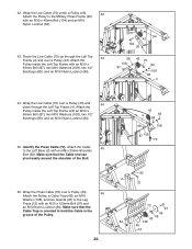
Route the Low Cable (70) over a Pulley (43). 41 Attach the Pulley to the Right Base (1) with an M10 x 50mm Bolt (105) and an M10 Nylon Locknut (84). 38. Wrap the Low Cable (70) under a Pulley (43). 38 Attach the Pulley, an M10 Washer (108), and two Half Guards (46) to the Left Top Frame (4) with an M10 x 65mm Bolt (87), two M10 Washers (108), two 1/2" Bushings (68), and an M10 Nylon Locknut (84). 84 108 68 43 70 46 95 108 68 87 9 40. Wrap the Low Cable (70) over a Pulley (43) and 39 through the Center Upright (9). Make sure that the Cable Trap is oriented to the ...
Route the Low Cable (70) over a Pulley (43). 41 Attach the Pulley to the Right Base (1) with an M10 x 50mm Bolt (105) and an M10 Nylon Locknut (84). 38. Wrap the Low Cable (70) under a Pulley (43). 38 Attach the Pulley, an M10 Washer (108), and two Half Guards (46) to the Left Top Frame (4) with an M10 x 65mm Bolt (87), two M10 Washers (108), two 1/2" Bushings (68), and an M10 Nylon Locknut (84). 84 108 68 43 70 46 95 108 68 87 9 40. Wrap the Low Cable (70) over a Pulley (43) and 39 through the Center Upright (9). Make sure that the Cable Trap is oriented to the ...
English Manual
Page 20
Route the Low Cable (70) up through the Left Top 43 Frame (4) and over a Pulley (43) and 44 down through the Left Top Frame (4). Identify the Press Cable (72). Wrap the Low Cable (70) over a Pulley (43). Attach the Pulley inside the Left Top Frame with an M10 x 65mm Bolt (87), two M10 Washers (108), two 1/2" Bushings (68), and an M10 Nylon Locknut (84). 70 84 43 104 20 68 108 87 43 70 84 108 68 4 44. Attach the Cable 45 to the Military Press Frame (20) with an M10 x 120mm Bolt (97) and an M10 Nylon Locknut (84). 42. Wrap the Low Cable (70) under a Pulley (43...
Route the Low Cable (70) up through the Left Top 43 Frame (4) and over a Pulley (43) and 44 down through the Left Top Frame (4). Identify the Press Cable (72). Wrap the Low Cable (70) over a Pulley (43). Attach the Pulley inside the Left Top Frame with an M10 x 65mm Bolt (87), two M10 Washers (108), two 1/2" Bushings (68), and an M10 Nylon Locknut (84). 70 84 43 104 20 68 108 87 43 70 84 108 68 4 44. Attach the Cable 45 to the Military Press Frame (20) with an M10 x 120mm Bolt (97) and an M10 Nylon Locknut (84). 42. Wrap the Low Cable (70) under a Pulley (43...