
Owners Manual
Page 1
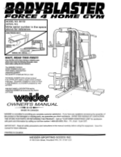
... viscddefli OWNER'S MANUAL MADE IN CANADA WEIDER is a series ofFOUR or FIVE NUMBERS, or a NUMBER proceeded by calling our toll free number 1-800-225-0653, Mon. - THE MODEL NUMBER of this product or find this unit to providing you have any questions concerning the assembly of this manual for assistance with parts and information by TWO Lb! If you complete customer satisfaction. The ASSEMBLY MANUAL MODEL NUMBER of...
... viscddefli OWNER'S MANUAL MADE IN CANADA WEIDER is a series ofFOUR or FIVE NUMBERS, or a NUMBER proceeded by calling our toll free number 1-800-225-0653, Mon. - THE MODEL NUMBER of this product or find this unit to providing you have any questions concerning the assembly of this manual for assistance with parts and information by TWO Lb! If you complete customer satisfaction. The ASSEMBLY MANUAL MODEL NUMBER of...
Owners Manual
Page 2
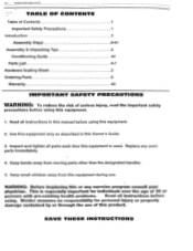
... this manual before using this Owner's Guide. 3. Weider assumes no responsibility for individuals over the age of 35 or persons with pre-existing health problems. Read all instructions before using this equipment. 2. Replace any exercise program consult your physician. This is used. Inspect and tighten all instructions in this equipment. 1. SAVE THESE INSTRUCTIONS WARNING: Before beginning this or any worn parts immediately. 4. Keep small children away from moving parts...
... this manual before using this Owner's Guide. 3. Weider assumes no responsibility for individuals over the age of 35 or persons with pre-existing health problems. Read all instructions before using this equipment. 2. Replace any exercise program consult your physician. This is used. Inspect and tighten all instructions in this equipment. 1. SAVE THESE INSTRUCTIONS WARNING: Before beginning this or any worn parts immediately. 4. Keep small children away from moving parts...
Owners Manual
Page 7
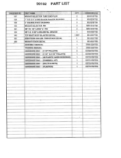
...SQUARE PIVOT BUSHING WEIGHT SELECTOR PIN 3/8' X 21/2" LONG 'L." PIN 3/8" I.D. 90102 PART LIST DIAGRAM NO. 127 128 129 130 131 132 140 141 ---,--142 PART NAME WEIGHT SELECTOR TUBE END PLUG 1' O.D. TWIN STACK DECAL WEIGHT STACK DECAL ASSEMBLY MANUAL TRAINING MANUAL HARDWARE BAG - (3 1/2" PULLEYS) HARDWARE BAG - (3 1/2' & 41/2' PULLEYS) HARDWARE BAG - (48 PLASTIC GUIDE BUSHINGS) HARDWARE BAG - (DUMBBELL KIT) HARDWARE BAG - (BOLTS & NUTS) HARDWARE BAG - (PLASTICS) 2 2 2 2 3 1 1 SET 1 1 ...F55 C5772-F55*F55 C5773-F55*F55 X 3/8" LONG METAL SPACER TOP MAST BODY BLASTER DECAL ARM PRESS 300 LBS.
...SQUARE PIVOT BUSHING WEIGHT SELECTOR PIN 3/8' X 21/2" LONG 'L." PIN 3/8" I.D. 90102 PART LIST DIAGRAM NO. 127 128 129 130 131 132 140 141 ---,--142 PART NAME WEIGHT SELECTOR TUBE END PLUG 1' O.D. TWIN STACK DECAL WEIGHT STACK DECAL ASSEMBLY MANUAL TRAINING MANUAL HARDWARE BAG - (3 1/2" PULLEYS) HARDWARE BAG - (3 1/2' & 41/2' PULLEYS) HARDWARE BAG - (48 PLASTIC GUIDE BUSHINGS) HARDWARE BAG - (DUMBBELL KIT) HARDWARE BAG - (BOLTS & NUTS) HARDWARE BAG - (PLASTICS) 2 2 2 2 3 1 1 SET 1 1 ...F55 C5772-F55*F55 C5773-F55*F55 X 3/8" LONG METAL SPACER TOP MAST BODY BLASTER DECAL ARM PRESS 300 LBS.
Owners Manual
Page 8
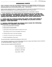
...: a. Serial number of the part from the original, un-opened carton. Country of the product (BODY BLASTER) the following action and information is required: 1. Weider provides replacement parts at 1-800-225-0653 Monday - Before ordering parts by phone have purchased, your name, address, and the date If your order by calling our product service number: 1-800-225-0653. 3. card must be directed to: Weider Sporting Goods Parts Service...
...: a. Serial number of the part from the original, un-opened carton. Country of the product (BODY BLASTER) the following action and information is required: 1. Weider provides replacement parts at 1-800-225-0653 Monday - Before ordering parts by phone have purchased, your name, address, and the date If your order by calling our product service number: 1-800-225-0653. 3. card must be directed to: Weider Sporting Goods Parts Service...
Owners Manual
Page 10
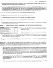
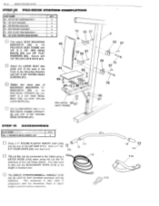
...assembly upright to the Seat tube welded on the PEC-DECK UPRIGHT (2) using 5/16" X 3 3/4" HEX HEAD BOLTS (73) by assembling a 5/16" FLAT WASHER (71) onto a 5/16" X 4 1/2' HEX HEAD BOLT (79) and bolting through the right side and ONLY the top hole of the Arm Press Upright. STEP 2 COMPLETING BASE ASSEMBLY & TOP FRAME ASSEMBLY... 3/8" NYLON LOCK NUT (81) and tighten only finger tight. Secure with the longer flat side located in the center of Step 2. Tighten this step is advisable that there are two sizes of holes along the edge of the Base, bolt HEAD BOLTS (107) and 5/16" NYLON LOCK ...
...assembly upright to the Seat tube welded on the PEC-DECK UPRIGHT (2) using 5/16" X 3 3/4" HEX HEAD BOLTS (73) by assembling a 5/16" FLAT WASHER (71) onto a 5/16" X 4 1/2' HEX HEAD BOLT (79) and bolting through the right side and ONLY the top hole of the Arm Press Upright. STEP 2 COMPLETING BASE ASSEMBLY & TOP FRAME ASSEMBLY... 3/8" NYLON LOCK NUT (81) and tighten only finger tight. Secure with the longer flat side located in the center of Step 2. Tighten this step is advisable that there are two sizes of holes along the edge of the Base, bolt HEAD BOLTS (107) and 5/16" NYLON LOCK ...
Owners Manual
Page 13
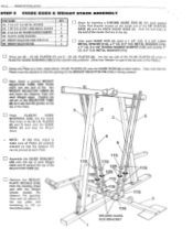
..., insert a pointed WEIGHT SELECTOR TUBE END PLUG (127) into the end of each Weight stack Position the roll pin in the 20 LB. PLATES (8) and fit them onto the GUIDE RODS (6) and atop the Weight Stack. El Remove the WEIGHT PLATE DECALS (142) from the backing sheet and affix the Weight Decals beside the Selector Pin opening for the WEIGHT SELECTOR PIN (130) is...
..., insert a pointed WEIGHT SELECTOR TUBE END PLUG (127) into the end of each Weight stack Position the roll pin in the 20 LB. PLATES (8) and fit them onto the GUIDE RODS (6) and atop the Weight Stack. El Remove the WEIGHT PLATE DECALS (142) from the backing sheet and affix the Weight Decals beside the Selector Pin opening for the WEIGHT SELECTOR PIN (130) is...
Owners Manual
Page 19
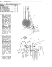
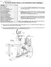
... STATION UPRIGHT (12). X 1 3/8" METAL SPACER (119), then into the TOP MAST CONNECTOR PLATE (15). X 1 3/8' LONG METAL SPACER (119), then continue bolting through the other GUIDE ROD (6), and finally through the TOP MAST CONNECTOR BRACKET (15), a GUIDE ROD (6), into a 3/8" I.D. Secure with 5/16" NYLON LOCK NUTS (72). PAGE 19 WEIDER SPORTING GOODS STEP 6 DIP STATION ASSE MBLY PART NAME...
... STATION UPRIGHT (12). X 1 3/8" METAL SPACER (119), then into the TOP MAST CONNECTOR PLATE (15). X 1 3/8' LONG METAL SPACER (119), then continue bolting through the other GUIDE ROD (6), and finally through the TOP MAST CONNECTOR BRACKET (15), a GUIDE ROD (6), into a 3/8" I.D. Secure with 5/16" NYLON LOCK NUTS (72). PAGE 19 WEIDER SPORTING GOODS STEP 6 DIP STATION ASSE MBLY PART NAME...

Owners Manual
Page 21
... of liquid detergent along the surface of the Leg Extension Tube. u Assemble one Pad Bar into the Pec-Deck Seat Frame Bracket location and the other one into the last link in one side of the Bar. PAGE 21 WEIDER SPORTING GOODS STEP 8 LEG EXTENSION ASSEMBLY PART. Slide on another 3 1/4" X 7' FOAM ROLLER (24). Using a 3/8" X 2 1/4" HEX HEAD BOLT (83), 3/8" FLAT WASHERS (80), and a 3/8" NYLON LOCK...
... of liquid detergent along the surface of the Leg Extension Tube. u Assemble one Pad Bar into the Pec-Deck Seat Frame Bracket location and the other one into the last link in one side of the Bar. PAGE 21 WEIDER SPORTING GOODS STEP 8 LEG EXTENSION ASSEMBLY PART. Slide on another 3 1/4" X 7' FOAM ROLLER (24). Using a 3/8" X 2 1/4" HEX HEAD BOLT (83), 3/8" FLAT WASHERS (80), and a 3/8" NYLON LOCK...
Owners Manual
Page 24
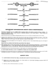
... is keeping cables and pulleys in the diagram. Periodically lubricate the Guide Rods with silicone or light machine oil to be set the height of the Dual Pulleys (T & U) at the Leg Extension. 5. IF YOUR HOME GYM FEELS LIKE IT IS BINDING UP READ THE FOLLOWING STEP 6. u NEVER PUT YOUR HANDS, FINGERS, OR OTHER PARTS OF YOUR BODY BETWEEN MOVING PARTS OR WEIGHTS WHILE THE GYM IS IN USE. Cable Traps...
... is keeping cables and pulleys in the diagram. Periodically lubricate the Guide Rods with silicone or light machine oil to be set the height of the Dual Pulleys (T & U) at the Leg Extension. 5. IF YOUR HOME GYM FEELS LIKE IT IS BINDING UP READ THE FOLLOWING STEP 6. u NEVER PUT YOUR HANDS, FINGERS, OR OTHER PARTS OF YOUR BODY BETWEEN MOVING PARTS OR WEIGHTS WHILE THE GYM IS IN USE. Cable Traps...
Owners Manual
Page 25
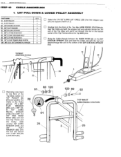
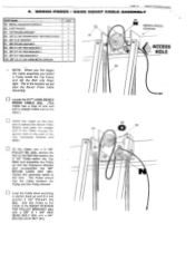
LAT PULL -DOWN & LOWER PULLEY ASSEMBLY PART NAME 61 4 1/2' PULLEY 62 31/2" PULLEY QTY 1 Select the 174 1/2" LONG LAT CABLE (28) (has two stopper balls and one adjuster sleeve on the DIP i 99 1/4' X 21/4" ROUND HEAD SCREW 1 120 3/8" I .D. X 2 3/4" HEX HEAD BOLT 1 4 Starting from the front of the Top Mast ARM PRESS STATION (3), feed the Cable end with the stopper ball and adjuster ferrule into Top Frame and the...
LAT PULL -DOWN & LOWER PULLEY ASSEMBLY PART NAME 61 4 1/2' PULLEY 62 31/2" PULLEY QTY 1 Select the 174 1/2" LONG LAT CABLE (28) (has two stopper balls and one adjuster sleeve on the DIP i 99 1/4' X 21/4" ROUND HEAD SCREW 1 120 3/8" I .D. X 2 3/4" HEX HEAD BOLT 1 4 Starting from the front of the Top Mast ARM PRESS STATION (3), feed the Cable end with the stopper ball and adjuster ferrule into Top Frame and the...
Owners Manual
Page 26
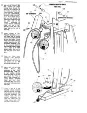
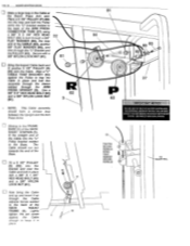
... a 3 1/2" PULLEY (B) ,(62), position the Cable coming down through the lower hole location on the DIP STATION UPRIGHT (12) making sure the bolt passes underneath and traps the Cable into the Pulley. I_J With a 3/8" X 2 3/4" HEX HEAD BOLT (92) assemble a 3/8" FLAT WASHER (80), a 3/8" I .D. Secure with a 3/8" NYLON LOCK NUT (81). Select another 3 1/2" PULLEY (C) (62) and set the Cable that is running between the GUIDE RODS (6) into the Pulley...
... a 3 1/2" PULLEY (B) ,(62), position the Cable coming down through the lower hole location on the DIP STATION UPRIGHT (12) making sure the bolt passes underneath and traps the Cable into the Pulley. I_J With a 3/8" X 2 3/4" HEX HEAD BOLT (92) assemble a 3/8" FLAT WASHER (80), a 3/8" I .D. Secure with a 3/8" NYLON LOCK NUT (81). Select another 3 1/2" PULLEY (C) (62) and set the Cable that is running between the GUIDE RODS (6) into the Pulley...
Owners Manual
Page 27
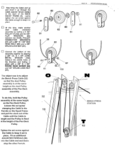
... fit over the Cables: Using a 3/8" X 2 3/4" HEX HEAD BOLT (92), bolt through the GUIDE BRACKET (49), then the WEIGHT SELECTOR TUBE (9), and then the Cable loop with a 5/16" X 1 1/2" HEX HEAD BOLT (109) and secure with a 5/16" NYLON LOCK NUT (72). 29 72 9 PEC-DECK SEAT FRAME 6 6 49 109 29 PE-GDECK WEIGHT STACK CABLE 0 2 0 62 81 2 O 9 30 LEG EXTENSION CABLE CITY 59 3/8' SPRING CLIP 62 3 1/2' PULLEY...
... fit over the Cables: Using a 3/8" X 2 3/4" HEX HEAD BOLT (92), bolt through the GUIDE BRACKET (49), then the WEIGHT SELECTOR TUBE (9), and then the Cable loop with a 5/16" X 1 1/2" HEX HEAD BOLT (109) and secure with a 5/16" NYLON LOCK NUT (72). 29 72 9 PEC-DECK SEAT FRAME 6 6 49 109 29 PE-GDECK WEIGHT STACK CABLE 0 2 0 62 81 2 O 9 30 LEG EXTENSION CABLE CITY 59 3/8' SPRING CLIP 62 3 1/2' PULLEY...
Owners Manual
Page 30
... Cable Trap Bracket can not slip off. Pull out on the other side of the PEC-PECK ARMS (17) and (18) lever with a 3/8" X 1 3/4' HEX HEAD BOLT (82) and a 3/8" NYLON LOCK NUT (81). Slide the METAL ADJUSTER FERRULE (58) against the stopper ball and tighten the set screw down tight!), against the lower Pulley. PEC-DECK ARM CABLE ASSEMBLY WEIDER SPORTING GOODS PART NAME 61 4 1/2" PULLEY 62 3 1/2' PULLEY...
... Cable Trap Bracket can not slip off. Pull out on the other side of the PEC-PECK ARMS (17) and (18) lever with a 3/8" X 1 3/4' HEX HEAD BOLT (82) and a 3/8" NYLON LOCK NUT (81). Slide the METAL ADJUSTER FERRULE (58) against the stopper ball and tighten the set screw down tight!), against the lower Pulley. PEC-DECK ARM CABLE ASSEMBLY WEIDER SPORTING GOODS PART NAME 61 4 1/2" PULLEY 62 3 1/2' PULLEY...

Owners Manual
Page 31
... PEC-DECK ARM CABLE (31) into each of the PEC-DECK STATION UPRIGHT (2) there are brackets welded to the bottom side of the PEC-DECK UPRIGHT (2). Bolt a PULLEY PIVOT BRACKET (53) into a 3 1/2" PULLEY (K) & (L) (62). To do this assembly in tension. Assemble a 4 1/2" PULLEY (M) (61) onto the Cable loop and fasten into the Weight stack. u The next step is in place using a 3/8" X 1 3/4" HEX HEAD BOLT (82) anda...
... PEC-DECK ARM CABLE (31) into each of the PEC-DECK STATION UPRIGHT (2) there are brackets welded to the bottom side of the PEC-DECK UPRIGHT (2). Bolt a PULLEY PIVOT BRACKET (53) into a 3 1/2" PULLEY (K) & (L) (62). To do this assembly in tension. Assemble a 4 1/2" PULLEY (M) (61) onto the Cable loop and fasten into the Weight stack. u The next step is in place using a 3/8" X 1 3/4" HEX HEAD BOLT (82) anda...
Owners Manual
Page 33
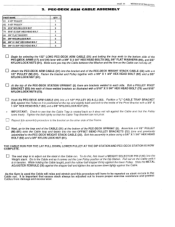
Fit the Cable into a 3 1/2" PULLEY (N) (62), remove the Nut on the Bolt that fastens the 3 1/2* Pulley BENCH PAGE 32 WEIDER SPORTING GOODS PRESS / HACK SQUAT CABLE ASSEMBLY PART NAME QTY 58 METAL ADJUSTER FERRULE 1 62 31/2" PULLEY 6 67 1/4' NYLON LOCK NUT 1 81 68 1/4' X 1 3/4" ROUND HEAD MACHINE SCREW 1 80 3/8" FLAT WASHER 4 81 3/8' NYLON LOCK NUT 5 82 3te* xi 3/4" HEX HEAD BOLT 3 83 3/8" X 2 1/4' HEX HEAD BOLT 1 94 3/8" X 5" HEX HEAD BOLT 1 122 3/8" I.D. 4. This...
Fit the Cable into a 3 1/2" PULLEY (N) (62), remove the Nut on the Bolt that fastens the 3 1/2* Pulley BENCH PAGE 32 WEIDER SPORTING GOODS PRESS / HACK SQUAT CABLE ASSEMBLY PART NAME QTY 58 METAL ADJUSTER FERRULE 1 62 31/2" PULLEY 6 67 1/4' NYLON LOCK NUT 1 81 68 1/4' X 1 3/4" ROUND HEAD MACHINE SCREW 1 80 3/8" FLAT WASHER 4 81 3/8' NYLON LOCK NUT 5 82 3te* xi 3/4" HEX HEAD BOLT 3 83 3/8" X 2 1/4' HEX HEAD BOLT 1 94 3/8" X 5" HEX HEAD BOLT 1 122 3/8" I.D. 4. This...
Owners Manual
Page 34
... LOCK NUT (81). The Cable should form a circular loop between the Upright and the Arm Press Arms. Moving to the FRAME BASE (1) of the HACK SQUAT STATION, (5), fit the straight end of the HACK SQUAT FRAME (5). THE ADDITIONAL LENGTH OF THE BOLT NJILL BE USED LATER IF THE USER DECIDES TO CONNECT BOTH WEIGHT STACKS. (SEE PAGE 37 USING DUAL STACKS) 58 TIGHItN SECOND...
... LOCK NUT (81). The Cable should form a circular loop between the Upright and the Arm Press Arms. Moving to the FRAME BASE (1) of the HACK SQUAT STATION, (5), fit the straight end of the HACK SQUAT FRAME (5). THE ADDITIONAL LENGTH OF THE BOLT NJILL BE USED LATER IF THE USER DECIDES TO CONNECT BOTH WEIGHT STACKS. (SEE PAGE 37 USING DUAL STACKS) 58 TIGHItN SECOND...
Owners Manual
Page 35
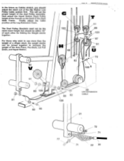
... holes of the Brackets and bolting in place. Connect the bottom , of the HACK SQUAT FRAME (5). Lightly tighten the set screw against the Cable to keep it set screw against the Cable enough to adjust the Bench Press Cable (32) so that the dual Pulley assembly is fixed at the same height as the dual Pulley assembly of the Pec-Deck Pulley. Loosen the sot screw clamping the Cablein the...
... holes of the Brackets and bolting in place. Connect the bottom , of the HACK SQUAT FRAME (5). Lightly tighten the set screw against the Cable to keep it set screw against the Cable enough to adjust the Bench Press Cable (32) so that the dual Pulley assembly is fixed at the same height as the dual Pulley assembly of the Pec-Deck Pulley. Loosen the sot screw clamping the Cablein the...
Owners Manual
Page 37
... will set the proper height of the Dip Station Low Pulley Cable system first. In the future as Cables stretch, you should be joined together to use more than the weight of a single stack, the weight stacks can be within 1/2" of the Hack Slide Frame. For those who wish to increase the weight of the Arm Press, Pec-Deck, Lat Pull...
... will set the proper height of the Dip Station Low Pulley Cable system first. In the future as Cables stretch, you should be joined together to use more than the weight of a single stack, the weight stacks can be within 1/2" of the Hack Slide Frame. For those who wish to increase the weight of the Arm Press, Pec-Deck, Lat Pull...
Owners Manual
Page 42
MOUNTING "L" BRACKETS 156) to the Cable using a LATCH HOOK (112) when using the Lat Bar for both Dumbbell exercises and leg exercises. X 5" FOAM GRIPS (38) onto each end. 105 The Lat Bar can be connected to the PEC-DECK UPRIGHT (2) with 5/16" X 2 3/4" HEX HEAD BOLT (76) and 5/16" NYLON LOCK NUTS (72). You may need to the Mounting Brackets with 1/4" X' 3/4" ROUND HEAD SCREWS (97). 42 2 5 97 -o 0- 44...
MOUNTING "L" BRACKETS 156) to the Cable using a LATCH HOOK (112) when using the Lat Bar for both Dumbbell exercises and leg exercises. X 5" FOAM GRIPS (38) onto each end. 105 The Lat Bar can be connected to the PEC-DECK UPRIGHT (2) with 5/16" X 2 3/4" HEX HEAD BOLT (76) and 5/16" NYLON LOCK NUTS (72). You may need to the Mounting Brackets with 1/4" X' 3/4" ROUND HEAD SCREWS (97). 42 2 5 97 -o 0- 44...
Owners Manual
Page 43
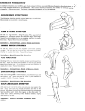
...soles of exercise, the number The key to a successful program is icreased to 4-5 times per week following stretches provide a good warm-up your foot. then bend the front leg and lean forward by moving your ... of rest between workouts is REGULAR exercise. Hold, then repeat on the ground; of the other side. Repeat. HAM STRING STRETCH Sit with one leg in front of workouts can and hold .... Pull your toes. Hold for both legs. Allow your back leg straight and back foot flat on the other and arms out, lean against the extended leg's inner thigh. Hold for 15 counts...
...soles of exercise, the number The key to a successful program is icreased to 4-5 times per week following stretches provide a good warm-up your foot. then bend the front leg and lean forward by moving your ... of rest between workouts is REGULAR exercise. Hold, then repeat on the ground; of the other side. Repeat. HAM STRING STRETCH Sit with one leg in front of workouts can and hold .... Pull your toes. Hold for both legs. Allow your back leg straight and back foot flat on the other and arms out, lean against the extended leg's inner thigh. Hold for 15 counts...


