

Instruction Manual
Page 1
... MODEL NUMBER of the product (WEEVSY39530) • The NAME of the product (WEIDER® PRO 9400 weight system) • The SERIAL NUMBER of the product (see the front cover of this manual) • The KEY NUMBER and DESCRIPTION of the part(s) (see the PART LIST and EXPLODED DRAWING attached in the centre of this manual) Part No. 200195 R0803A Printed in the space above for future reference. USER'S MANUAL Class HC Fitness...
... MODEL NUMBER of the product (WEEVSY39530) • The NAME of the product (WEIDER® PRO 9400 weight system) • The SERIAL NUMBER of the product (see the front cover of this manual) • The KEY NUMBER and DESCRIPTION of the part(s) (see the PART LIST and EXPLODED DRAWING attached in the centre of this manual) Part No. 200195 R0803A Printed in the space above for future reference. USER'S MANUAL Class HC Fitness...

Instruction Manual
Page 2
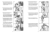
TABLE OF CONTENTS IMPORTANT PRECAUTIONS 3 BEFORE YOU BEGIN 4 ASSEMBLY 5 ADJUSTMENTS 22 WEIGHT RESISTANCE CHART 24 TROUBLESHOOTING 25 CABLE DIAGRAMS 26 ORDERING REPLACEMENT PARTS Back Cover Note: A PART IDENTIFICATION CHART and a PART LIST/EXPLODED DRAWING are attached in the centre of ICON Health & Fitness, Inc. 2 Leg Lever Cable (75) 3 4 2 1 Swivel Low Cable (72) 3 6 8 1 2 5 4 7 9 Swivel Cable (17) 1 3 5 2 4 27 WEIDER is a registered trademark of this manual. Remove the PART IDENTIFICATION CHART and the PART LIST/EXPLODED DRAWING before beginning assembly.
TABLE OF CONTENTS IMPORTANT PRECAUTIONS 3 BEFORE YOU BEGIN 4 ASSEMBLY 5 ADJUSTMENTS 22 WEIGHT RESISTANCE CHART 24 TROUBLESHOOTING 25 CABLE DIAGRAMS 26 ORDERING REPLACEMENT PARTS Back Cover Note: A PART IDENTIFICATION CHART and a PART LIST/EXPLODED DRAWING are attached in the centre of ICON Health & Fitness, Inc. 2 Leg Lever Cable (75) 3 4 2 1 Swivel Low Cable (72) 3 6 8 1 2 5 4 7 9 Swivel Cable (17) 1 3 5 2 4 27 WEIDER is a registered trademark of this manual. Remove the PART IDENTIFICATION CHART and the PART LIST/EXPLODED DRAWING before beginning assembly.

Instruction Manual
Page 3
... routed, the weight system will fall with pre-existing health problems. Read all instructions before using. The cable diagrams on all of this or any time while exercising, stop immediately and make sure that all times. 14. Cable Identification Chart Butterfly Cable (69)-1475mm Swivel Low Cable (72)-5207mm Squat Cable (73)-4425mm Swivel High Cable (74)-3213mm Leg Lever Cable (75)-2398mm Lat Cable (88)-2267mm Swivel Cable (17)-3005mm Lat Cable...
... routed, the weight system will fall with pre-existing health problems. Read all instructions before using. The cable diagrams on all of this or any time while exercising, stop immediately and make sure that all times. 14. Cable Identification Chart Butterfly Cable (69)-1475mm Swivel Low Cable (72)-5207mm Squat Cable (73)-4425mm Swivel High Cable (74)-3213mm Leg Lever Cable (75)-2398mm Lat Cable (88)-2267mm Swivel Cable (17)-3005mm Lat Cable...
Instruction Manual
Page 4
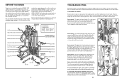
... of cable used . See drawing 3. Reattach the Pulley and the Pulley Covers between a set of this manual. 25 73 87 68 101 100 63 100 68 87 75 100 34 64 68 87 If the cables are properly tightened each side) Adjustment Handle Backrest Low Pulley Station Seat Adjustment Handle Leg Lever Squat Arm Backrest Adjustment Knob WARNING DECAL 2 Weight Stack Squat Knee Rest Handle Curl Bar Ab Strap 4 TROUBLESHOOTING Make...
... of cable used . See drawing 3. Reattach the Pulley and the Pulley Covers between a set of this manual. 25 73 87 68 101 100 63 100 68 87 75 100 34 64 68 87 If the cables are properly tightened each side) Adjustment Handle Backrest Low Pulley Station Seat Adjustment Handle Leg Lever Squat Arm Backrest Adjustment Knob WARNING DECAL 2 Weight Stack Squat Knee Rest Handle Curl Bar Ab Strap 4 TROUBLESHOOTING Make...

Instruction Manual
Page 5
... need grease or petroleum jelly, a small amount of its weight and size, the weight system should be used in assembly, a PART IDENTIFICATION CHART is not in separate bags. Lay the chart on this stage, you will be assembled successfully by anyone. Seat Assembly-During the final stage, you begin by deciding to make sure to read it . The butterfly arm resistance listed is the resistance for the Weight...
... need grease or petroleum jelly, a small amount of its weight and size, the weight system should be used in assembly, a PART IDENTIFICATION CHART is not in separate bags. Lay the chart on this stage, you will be assembled successfully by anyone. Seat Assembly-During the final stage, you begin by deciding to make sure to read it . The butterfly arm resistance listed is the resistance for the Weight...
Instruction Manual
Page 6
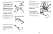
...It may be helpful to place tape over the heads of the Squat Arm (32), first loosen the Adjustment Knob (115) on the Long Pin w/Tether (112) to hold them in the Squat Slider (not shown), and retighten the Handle. Attach the tether on the Squat Bracket (37). The height of the...(101). ping Screw (14). Make sure that you understand all of the information on page 5 before you begin assembling the weight system. 2 24 120 14 Locate and open end of the holes in place. See the inset drawing. the Squat Knee Rest must be adjusted in the same way using the three Adjustment Handles (65)....
...It may be helpful to place tape over the heads of the Squat Arm (32), first loosen the Adjustment Knob (115) on the Long Pin w/Tether (112) to hold them in the Squat Slider (not shown), and retighten the Handle. Attach the tether on the Squat Bracket (37). The height of the...(101). ping Screw (14). Make sure that you understand all of the information on page 5 before you begin assembling the weight system. 2 24 120 14 Locate and open end of the holes in place. See the inset drawing. the Squat Knee Rest must be adjusted in the same way using the three Adjustment Handles (65)....

Instruction Manual
Page 7
... butterfly arms, insert the "L"-pins w/Tethers (60) into the same set up . Note: Due to the cables and pulleys, the amount of resistance at each weight station. Adjust the length of the Chain between the Lat Bar and the Lat Cable so the Lat Bar is touching the Weights. Press a 38mm Square Inner Cap (67) into the top of the Seat Upright (9). Attach the Upright Extension (12) to the Seat Upright with...
... butterfly arms, insert the "L"-pins w/Tethers (60) into the same set up . Note: Due to the cables and pulleys, the amount of resistance at each weight station. Adjust the length of the Chain between the Lat Bar and the Lat Cable so the Lat Bar is touching the Weights. Press a 38mm Square Inner Cap (67) into the top of the Seat Upright (9). Attach the Upright Extension (12) to the Seat Upright with...

Instruction Manual
Page 8
... all parts have been properly tightened. Do not tighten the Locknuts yet. Finger tighten an M10 Nylon Locknut (87) onto each Carriage Bolt. Before using the weight system, pull each cable a few times to remove the slack by tightening the cables. See TROUBLESHOOTING on the following page. If there is tight. 38 62. Turn the knob on page 26 and 27 of the Squat Upright (4). Attach...
... all parts have been properly tightened. Do not tighten the Locknuts yet. Finger tighten an M10 Nylon Locknut (87) onto each Carriage Bolt. Before using the weight system, pull each cable a few times to remove the slack by tightening the cables. See TROUBLESHOOTING on the following page. If there is tight. 38 62. Turn the knob on page 26 and 27 of the Squat Upright (4). Attach...

Instruction Manual
Page 9
... set of 9 holes in the location shown. Next, slide ten Weights (44) onto the Weight Guides. Make sure that the Weight Tube is facing downward. Slide the Top Weight onto the Weight Guides (42). Apply a number "10" decal to the Squat Bracket (37) with two M8 x 20mm Button Head Screws (51). Attach the Seat (16) to the Squat Arm (32) with two M10 x 65mm Carriage Bolts...
... set of 9 holes in the location shown. Next, slide ten Weights (44) onto the Weight Guides. Make sure that the Weight Tube is facing downward. Slide the Top Weight onto the Weight Guides (42). Apply a number "10" decal to the Squat Bracket (37) with two M8 x 20mm Button Head Screws (51). Attach the Seat (16) to the Squat Arm (32) with two M10 x 65mm Carriage Bolts...

Instruction Manual
Page 10
...; Attach the Pulley and a pair of the M10 Nylon Locknuts (87) used in the indicated bracket on the Top Frame (6) with grease. Wrap the Squat Cable (73) over the weight stack and insert the Weight Pin (50). Screw the end of holes from the top in steps 4-13. Locate and open the parts bag labelled "SEAT ASSEMBLY." Wet the Pad Tube with an M10 x 50mm Bolt...
...; Attach the Pulley and a pair of the M10 Nylon Locknuts (87) used in the indicated bracket on the Top Frame (6) with grease. Wrap the Squat Cable (73) over the weight stack and insert the Weight Pin (50). Screw the end of holes from the top in steps 4-13. Locate and open the parts bag labelled "SEAT ASSEMBLY." Wet the Pad Tube with an M10 x 50mm Bolt...
Instruction Manual
Page 11
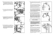
... is 3213mm long and has a ball on one end and a threaded bolt on the bot- 49. Attach the Right Butterfly Arm (26) to pivot easily. Locate and open the parts bags labelled "CABLE ASSEMBLY", "PULLEY COVERS", and "PULLEYS." 18 74 78 40 122 30 87 Lubricate the M10 x 165mm Bolt (30) with the Bolt, the two Plastic Washers, two Butterfly Caps (57), two M10...
... is 3213mm long and has a ball on one end and a threaded bolt on the bot- 49. Attach the Right Butterfly Arm (26) to pivot easily. Locate and open the parts bags labelled "CABLE ASSEMBLY", "PULLEY COVERS", and "PULLEYS." 18 74 78 40 122 30 87 Lubricate the M10 x 165mm Bolt (30) with the Bolt, the two Plastic Washers, two Butterfly Caps (57), two M10...
Instruction Manual
Page 12
... 6 93 87 22. Then, tighten the M12 Nut against the Washer. 23. Route the Swivel Low Cable (72) under a 90mm Pulley (78). Attach the Pulley and a pair of the Weight Tube (43). Place a 50mm Washer (1) on the Top Frame (6) with an M10 x 50mm Bolt (100) and an M10 Nylon Locknut (87). Attach an M10 x 65mm Bolt (18), two M10 Washers...
... 6 93 87 22. Then, tighten the M12 Nut against the Washer. 23. Route the Swivel Low Cable (72) under a 90mm Pulley (78). Attach the Pulley and a pair of the Weight Tube (43). Place a 50mm Washer (1) on the Top Frame (6) with an M10 x 50mm Bolt (100) and an M10 Nylon Locknut (87). Attach an M10 x 65mm Bolt (18), two M10 Washers...
Instruction Manual
Page 13
... Attach the end of the Butterfly Upright (3) with an M10 x 50mm Bolt (100) and an M10 Nylon Locknut (87). Locate the Lat Cable (88), which is 2263mm long and has a ball on one end and a ball on the Swivel Carriage (46) with an M10 x 50mm Bolt (100) and an M10 Nylon Locknut (87). Attach the Pulley and a pair of Pulley Covers...
... Attach the end of the Butterfly Upright (3) with an M10 x 50mm Bolt (100) and an M10 Nylon Locknut (87). Locate the Lat Cable (88), which is 2263mm long and has a ball on one end and a ball on the Swivel Carriage (46) with an M10 x 50mm Bolt (100) and an M10 Nylon Locknut (87). Attach the Pulley and a pair of Pulley Covers...

Instruction Manual
Page 14
... end of the Lat Cable (88) inside of the Cable through the Seat Upright (9) and attach it to the Pivot Bracket (70) on the Butterfly Upright (3) 102 with an M8 x 20mm Shoulder Bolt (103) and an M8 Nylon Locknut (34). 33. Locate the Butterfly Cable (69), which is the 32 shortest Cable. Attach the Pulley and a pair of Pulley Covers (8) to the second set of holes...
... end of the Lat Cable (88) inside of the Cable through the Seat Upright (9) and attach it to the Pivot Bracket (70) on the Butterfly Upright (3) 102 with an M8 x 20mm Shoulder Bolt (103) and an M8 Nylon Locknut (34). 33. Locate the Butterfly Cable (69), which is the 32 shortest Cable. Attach the Pulley and a pair of Pulley Covers (8) to the second set of holes...

Instruction Manual
Page 15
... (116) 25mm Round Outer Cap (121) Note: Assembly is provided to the key number of the part from the PART LIST in the centre of this manual. If you identify the small parts used in separate bags. WAIT UNTIL YOU BEGIN EACH ASSEMBLY STAGE TO OPEN THE PARTS BAG LABELLED FOR THAT ASSEMBLY STAGE. The number in parenthesis below each stage is packaged in...
... (116) 25mm Round Outer Cap (121) Note: Assembly is provided to the key number of the part from the PART LIST in the centre of this manual. If you identify the small parts used in separate bags. WAIT UNTIL YOU BEGIN EACH ASSEMBLY STAGE TO OPEN THE PARTS BAG LABELLED FOR THAT ASSEMBLY STAGE. The number in parenthesis below each stage is packaged in...

Instruction Manual
Page 16
... Shoulder Bolt (103) M8 x 20mm Button Head Screw (51) M4 x 20mm Selftapping Screw (14) M6 x 16mm Screw (114) M10 x 60mm Bolt (59) M10 x 65mm Bolt (18) M10 x 65mm Carriage Bolt (110) M10 x 70mm Bolt (85) M10 x 70mm Carriage Bolt (106) M10 x 80mm Button Head Bolt (104) M10 x 80mm Bolt (107) M8 x 85mm Bolt (94) M10 x 85mm Bolt (96) M10 x 95mm Bolt (92) M10 x 165mm Bolt (30) PART IDENTIFICATION CHART-Model...
... Shoulder Bolt (103) M8 x 20mm Button Head Screw (51) M4 x 20mm Selftapping Screw (14) M6 x 16mm Screw (114) M10 x 60mm Bolt (59) M10 x 65mm Bolt (18) M10 x 65mm Carriage Bolt (110) M10 x 70mm Bolt (85) M10 x 70mm Carriage Bolt (106) M10 x 80mm Button Head Bolt (104) M10 x 80mm Bolt (107) M8 x 85mm Bolt (94) M10 x 85mm Bolt (96) M10 x 95mm Bolt (92) M10 x 165mm Bolt (30) PART IDENTIFICATION CHART-Model...

Instruction Manual
Page 17
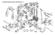
... Carriage Bolt Outer Cap w/Hole Long Pin w/Tether Large Pulley Cover M6 x 16mm Screw Adjustment Knob 20mm x 40mm Inner Cap 25mm x 40mm Inner Cap M12 Nut 115mm Pulley M4 Washer 25mm Round Outer Cap Right Double Cover User's Manual Exercise Guide Grease Package Note: "#" indicates a non-illustrated part. REMOVE THIS PART LIST/EXPLODED DRAWING FROM THE MANUAL. Qty. Specifications are subject to change without notice. Description Key No. Qty. SAVE THIS PART LIST/EXPLODED...
... Carriage Bolt Outer Cap w/Hole Long Pin w/Tether Large Pulley Cover M6 x 16mm Screw Adjustment Knob 20mm x 40mm Inner Cap 25mm x 40mm Inner Cap M12 Nut 115mm Pulley M4 Washer 25mm Round Outer Cap Right Double Cover User's Manual Exercise Guide Grease Package Note: "#" indicates a non-illustrated part. REMOVE THIS PART LIST/EXPLODED DRAWING FROM THE MANUAL. Qty. Specifications are subject to change without notice. Description Key No. Qty. SAVE THIS PART LIST/EXPLODED...
Instruction Manual
Page 18
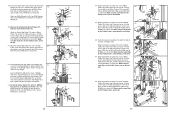
... 94 39 39 115 37 35 36 79 41 108 14 24 22 108 36 120 120 110 108 14 14 14 14 EXPLODED DRAWING-Model No.
... 94 39 39 115 37 35 36 79 41 108 14 24 22 108 36 120 120 110 108 14 14 14 14 EXPLODED DRAWING-Model No.


