Service Manual
Page 2
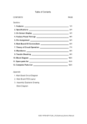
Specifications 3. Trouble Shooting 10. Main Board I/O Connections 7. Block Diagram 11. Main Board PCB Layout 3. Factory Preset Timings 5. Theory of Contents CONTENTS Sections 1. Spare parts list 12. Complete Parts List Appendix 1. Assembly Explosion Drawing Block Diagram PAGE 1-1 2-1 3-1 4-1 5-1 6-1 7-1 8-1 9-1 10-1 11-1 12-1 VIZIO VP50HDTV120A_LPL/Samsung Service Manual Waveforms 9. Pin Assignment 6. Main Board Circuit Diagram 2. Table of Circuit Operation 8. Features 2. On Screen Display 4.
Specifications 3. Trouble Shooting 10. Main Board I/O Connections 7. Block Diagram 11. Main Board PCB Layout 3. Factory Preset Timings 5. Theory of Contents CONTENTS Sections 1. Spare parts list 12. Complete Parts List Appendix 1. Assembly Explosion Drawing Block Diagram PAGE 1-1 2-1 3-1 4-1 5-1 6-1 7-1 8-1 9-1 10-1 11-1 12-1 VIZIO VP50HDTV120A_LPL/Samsung Service Manual Waveforms 9. Pin Assignment 6. Main Board Circuit Diagram 2. Table of Circuit Operation 8. Features 2. On Screen Display 4.

Service Manual
Page 17
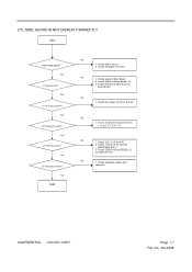
... +5VSB &DV12? 2. Check sync input 4. Check VGA SOG rout if analog (SOG) N0 1.Check J10 PIN14 2.Is Power Board ok? N0 It means data to LVDS 1.Is J7 connecting OK? 2.Check J1 +5V & +12V 3.Is panel ok? 4. Check video cable 2. Is DC-DC OK? 4. ...
... +5VSB &DV12? 2. Check sync input 4. Check VGA SOG rout if analog (SOG) N0 1.Check J10 PIN14 2.Is Power Board ok? N0 It means data to LVDS 1.Is J7 connecting OK? 2.Check J1 +5V & +12V 3.Is panel ok? 4. Check video cable 2. Is DC-DC OK? 4. ...

Service Manual
Page 21
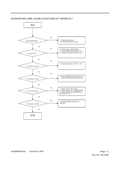
... Yes N0 U10 pin2 Yes N0 U33 pin2 Yes N0 U7 pin2 Yes U9 pin2 Yes U35 pin2 The voltage is about + 5V 1.Check power board 2.Check power cable connection J10 The voltage is about + 12V while power switch on 1.J10 connection good 2.Check J10 Pin2,3 transform +5V_TUNER 3.Check power... board The voltage is about +5V while power switch on 1.J10 connection good 2. SG-0246 DO NOT COPY Page 9-5 File No. Check U14 OPWRSB & OPCTRL2 Pin ...
... Yes N0 U10 pin2 Yes N0 U33 pin2 Yes N0 U7 pin2 Yes U9 pin2 Yes U35 pin2 The voltage is about + 5V 1.Check power board 2.Check power cable connection J10 The voltage is about + 12V while power switch on 1.J10 connection good 2.Check J10 Pin2,3 transform +5V_TUNER 3.Check power... board The voltage is about +5V while power switch on 1.J10 connection good 2. SG-0246 DO NOT COPY Page 9-5 File No. Check U14 OPWRSB & OPCTRL2 Pin ...
Service Manual
Page 23
Yes U1.U2 output correct? Yes U7.U8 Volt correct? CONFIDENTIAL - SG-0246 Yes END N0 1. Check the player of Main Board 2. Check signal of source N0 1. Check VCC of U7 and U8 (R202.R203.R271). 3. DO NOT COPY Page 9-7 File No. Yes J1 input correct? Yes ... source 2. Check the wire of U1 and U2. Check C200(Ch R) and C201(Ch L) and C271 (Ch CT) N0 1. Check the output volt of Main Board to Audio Board N0 1. Check signal of Audio...
Yes U1.U2 output correct? Yes U7.U8 Volt correct? CONFIDENTIAL - SG-0246 Yes END N0 1. Check the player of Main Board 2. Check signal of source N0 1. Check VCC of U7 and U8 (R202.R203.R271). 3. DO NOT COPY Page 9-7 File No. Yes J1 input correct? Yes ... source 2. Check the wire of U1 and U2. Check C200(Ch R) and C201(Ch L) and C271 (Ch CT) N0 1. Check the output volt of Main Board to Audio Board N0 1. Check signal of Audio...
Service Manual
Page 24
Yes U7.U8 Volt correct? Check signal of Audio Board (J1) 3. Check signal of Main Board 2. Check VCC of U7 (R202.R203). 3. Check C200(Ch R) and C201(Ch L) and C170 (Ch SW) and C171 (VB) N0 1. DO NOT COPY Page 9-8 File ...
Yes U7.U8 Volt correct? Check signal of Audio Board (J1) 3. Check signal of Main Board 2. Check VCC of U7 (R202.R203). 3. Check C200(Ch R) and C201(Ch L) and C170 (Ch SW) and C171 (VB) N0 1. DO NOT COPY Page 9-8 File ...

