

Service Manual
Page 25
The main board receives different types of video signal into system request power source. SG-0184 DO NOT COPY Page 6-1 File No. CONFIDENTIAL - Afterward, the MTK8205 Ic process the signals control the various functions of the monitor and outputs control signal, video signal and power to the 42''PDP XGA panel to be displayed. Chapter 6 Block Diagram 42'' PDP XGA panel The TV system block diagram is powered by power board that transforms AC source of 100V~240V AC +/- 10% @ 50/60 HZ into the MTK8205 Ic.
The main board receives different types of video signal into system request power source. SG-0184 DO NOT COPY Page 6-1 File No. CONFIDENTIAL - Afterward, the MTK8205 Ic process the signals control the various functions of the monitor and outputs control signal, video signal and power to the 42''PDP XGA panel to be displayed. Chapter 6 Block Diagram 42'' PDP XGA panel The TV system block diagram is powered by power board that transforms AC source of 100V~240V AC +/- 10% @ 50/60 HZ into the MTK8205 Ic.

Service Manual
Page 29
DO NOT COPY Description "POWRSW" "+12V" "+12V" "+12V" "GND" "GND" "GND" "GND" "+5V" "+5V" "+5V" "RLY_ON" "VS_ON" Page 7-1 File No. Chapter7 Main Board I/o Connections J7 CONNECTION (TOP→BOTTOM) Pin 1 2 3 4 5 6 7 8 9 10 11 12 Description "Auto" "Left" "Right" "Down" "Gnd" "Up" "Menu" "Source" "Power" "LED" "IR" "+5V" J1 CONNECTION (TOP→BOTTOM) Pin 1 2 3 4 5 6 7 8 9 10 11 12 13 CONFIDENTIAL - SG-0184
DO NOT COPY Description "POWRSW" "+12V" "+12V" "+12V" "GND" "GND" "GND" "GND" "+5V" "+5V" "+5V" "RLY_ON" "VS_ON" Page 7-1 File No. Chapter7 Main Board I/o Connections J7 CONNECTION (TOP→BOTTOM) Pin 1 2 3 4 5 6 7 8 9 10 11 12 Description "Auto" "Left" "Right" "Down" "Gnd" "Up" "Menu" "Source" "Power" "LED" "IR" "+5V" J1 CONNECTION (TOP→BOTTOM) Pin 1 2 3 4 5 6 7 8 9 10 11 12 13 CONFIDENTIAL - SG-0184

Service Manual
Page 33
...File No. SG-0184 Then transfer to MTK8205 the MTK8205 generates the vertical and horizontal timing signals for display device. The operation of TV route TV signal is processes to the tuner and output to MM1492 (switch) then transfer to the MTK8205 the MTK8205 generates the vertical and ... HDMI transfer to indicate the status of HDTV & Component route HDTV & Component signal is transmission signal to main board MM1492 (Switch) and output to MT5351. The operation of keypad There are "Power, Menu, CH+,CH-, VOL+ ,VOL -, Input". They are 7 keys to control and select the function ...
...File No. SG-0184 Then transfer to MTK8205 the MTK8205 generates the vertical and horizontal timing signals for display device. The operation of TV route TV signal is processes to the tuner and output to MM1492 (switch) then transfer to the MTK8205 the MTK8205 generates the vertical and ... HDMI transfer to indicate the status of HDTV & Component route HDTV & Component signal is transmission signal to main board MM1492 (Switch) and output to MT5351. The operation of keypad There are "Power, Menu, CH+,CH-, VOL+ ,VOL -, Input". They are 7 keys to control and select the function ...
Service Manual
Page 38
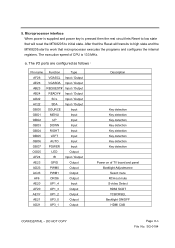
Microprocessor interface When power is supplied and power key is 133 MHz. The execution speed of TV board and panel Backlight Adjustmance Select mute RCA out mute S-video Detect HDMI SCDT YCBCRSEL Backlight ON/OFF HDMI CAB CONFIDENTIAL - 5. DO NOT COPY Page 8-6 ...SDA Input / Output OBO0 SOURCE Input OBO1 MENU Input OBO2 UP Input OBO3 DOWN Input OBO4 RIGHT Input OBO5 LEFT Input OBO6 AUTO Input OBO7 POWER Input OGO5 LED Output AF24 IR Input / Output AE23 GPIO Output AD23 PWM0 Output AC23 PWM1 Output AF6 ORO6 Output AE20 UP1_4 Input AF20 ...
Microprocessor interface When power is supplied and power key is 133 MHz. The execution speed of TV board and panel Backlight Adjustmance Select mute RCA out mute S-video Detect HDMI SCDT YCBCRSEL Backlight ON/OFF HDMI CAB CONFIDENTIAL - 5. DO NOT COPY Page 8-6 ...SDA Input / Output OBO0 SOURCE Input OBO1 MENU Input OBO2 UP Input OBO3 DOWN Input OBO4 RIGHT Input OBO5 LEFT Input OBO6 AUTO Input OBO7 POWER Input OGO5 LED Output AF24 IR Input / Output AE23 GPIO Output AD23 PWM0 Output AC23 PWM1 Output AF6 ORO6 Output AE20 UP1_4 Input AF20 ...

Service Manual
Page 105
... is lighted Ye LED is in ? Is DC-DC OK? 4. Check video cable 2. Is the timing supported? 3. Check P3 D-sub Input correct END CONFIDENTIAL - Is Power board output +5V? 2. SG-0184 N0 1.Is U9 working good? 2.Is U11&U12 working good? 3.IS U10 working ok? Ye U9 no data in...
... is lighted Ye LED is in ? Is DC-DC OK? 4. Check video cable 2. Is the timing supported? 3. Check P3 D-sub Input correct END CONFIDENTIAL - Is Power board output +5V? 2. SG-0184 N0 1.Is U9 working good? 2.Is U11&U12 working good? 3.IS U10 working ok? Ye U9 no data in...

Service Manual
Page 109
... on 1.Check U9 GPIO Pin 2.Check U14 N0 The voltage is about +1.8V 1.Check J1 Connect 2.Check U5&L5 The voltage is about +1.25V while power switch on 1.J1 connection good 2. TROUBLE OF DC-DC CONVERTER Start J1 PIN 9,10,11 Ye J1 PIN 2,3,4,5 Ye U7 pin 5 6 7 8 ... pin2 U13 pin2 END The voltage is about + 5V N0 1.Check power board 2.Check power cable connection J1 N0 The voltage is about + 12V while power switch on 1.J1 connection good 2.Check U9 GPIO Pin 3.Check power board N0 The voltage is about +5V while power switch on 1.Check J1 Connect 2.Check U13 CONFIDENTIAL -
... on 1.Check U9 GPIO Pin 2.Check U14 N0 The voltage is about +1.8V 1.Check J1 Connect 2.Check U5&L5 The voltage is about +1.25V while power switch on 1.J1 connection good 2. TROUBLE OF DC-DC CONVERTER Start J1 PIN 9,10,11 Ye J1 PIN 2,3,4,5 Ye U7 pin 5 6 7 8 ... pin2 U13 pin2 END The voltage is about + 5V N0 1.Check power board 2.Check power cable connection J1 N0 The voltage is about + 12V while power switch on 1.J1 connection good 2.Check U9 GPIO Pin 3.Check power board N0 The voltage is about +5V while power switch on 1.Check J1 Connect 2.Check U13 CONFIDENTIAL -


