

Service Manual
Page 11
...) f. MUTE (ON/OFF) h. AUDIO SOURCE (HDMI/DVII) NOTE: While main or pip exists HDMI source, audio option will add an AUDIO SOURCE item. TV RATING c. Adjust the CONTRAST (0~100) d. RESET ALL SETTING e. IMAGE CLEANER A. Adjust the SHARPNESS (0~100) B. SPEAKERS (ON/OFF) i. PARENTAL CONTROL: a. LANGUAGE (ENGLISH/FRANÇAIS/ ESPAÑOL...
...) f. MUTE (ON/OFF) h. AUDIO SOURCE (HDMI/DVII) NOTE: While main or pip exists HDMI source, audio option will add an AUDIO SOURCE item. TV RATING c. Adjust the CONTRAST (0~100) d. RESET ALL SETTING e. IMAGE CLEANER A. Adjust the SHARPNESS (0~100) B. SPEAKERS (ON/OFF) i. PARENTAL CONTROL: a. LANGUAGE (ENGLISH/FRANÇAIS/ ESPAÑOL...
Service Manual
Page 38
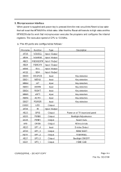
...detection Key detection Key detection Key detection Key detection Power on of CPU is pressed then the rest circuit lets Reset to initial state. The execution speed of TV board and panel Backlight Adjustmance Select mute RCA out mute S-video Detect HDMI SCDT YCBCRSEL Backlight ON/OFF HDMI ...CAB CONFIDENTIAL - a. Microprocessor interface When power is supplied and power key is 133 MHz. After that the Reset will transits to high state...
...detection Key detection Key detection Key detection Key detection Power on of CPU is pressed then the rest circuit lets Reset to initial state. The execution speed of TV board and panel Backlight Adjustmance Select mute RCA out mute S-video Detect HDMI SCDT YCBCRSEL Backlight ON/OFF HDMI ...CAB CONFIDENTIAL - a. Microprocessor interface When power is supplied and power key is 133 MHz. After that the Reset will transits to high state...

Service Manual
Page 44
...Two clock cycles are in the mode register. CONFIDENTIAL - Issue precharge commands for all bank recharge with low to A8 to low for "DLL reset". The state of clock input is not defined, therefore the mode register must be in the mode register. The additional 200 cycles of address ... are requested to complete the write operation in all banks of DDR SDRAM. It programs CAS latency, addressing mode, burst length, test mode, DLL reset and various vendor specific options to BA0) 7. DO NOT COPY Page 8-12 File No. The default value of different applications. Issue a mode register...
...Two clock cycles are in the mode register. CONFIDENTIAL - Issue precharge commands for all bank recharge with low to A8 to low for "DLL reset". The state of clock input is not defined, therefore the mode register must be in the mode register. The additional 200 cycles of address ... are requested to complete the write operation in all banks of DDR SDRAM. It programs CAS latency, addressing mode, burst length, test mode, DLL reset and various vendor specific options to BA0) 7. DO NOT COPY Page 8-12 File No. The default value of different applications. Issue a mode register...

Service Manual
Page 49
BLOCK DIAGRAM 1. Table 5 defines the valid register command sequences. CONFIDENTIAL - SG-0184 Note that the Erase Suspend (B0H) and Erase Resume (30H) commands are selected by writing specific address and data sequences into the command register. COMMAND DEFINITIONS Device operations are valid only while the Sector Erase operation is in the improper sequence will reset the device to the read mode. DO NOT COPY Page 8-17 File No. Writing incorrect address and data values or writing them in progress.
BLOCK DIAGRAM 1. Table 5 defines the valid register command sequences. CONFIDENTIAL - SG-0184 Note that the Erase Suspend (B0H) and Erase Resume (30H) commands are selected by writing specific address and data sequences into the command register. COMMAND DEFINITIONS Device operations are valid only while the Sector Erase operation is in the improper sequence will reset the device to the read mode. DO NOT COPY Page 8-17 File No. Writing incorrect address and data values or writing them in progress.

Service Manual
Page 50
... Bypass mode, only two write cycles are required to facilitate faster programming. Writing incorrect address and data values or writing them in the improper sequence resets the device to VIH. WRITE COMMANDS/COMMAND SEQUENCES To program data to the device or erase sectors of the address bits required to the device...
... Bypass mode, only two write cycles are required to facilitate faster programming. Writing incorrect address and data values or writing them in the improper sequence resets the device to VIH. WRITE COMMANDS/COMMAND SEQUENCES To program data to the device or erase sectors of the address bits required to the device...

Service Manual
Page 51
READ/RESET COMMAND The read /reset command sequence into the command register. A valid command must then be written to place the device in the DC Characteristics table represents the active current ... timings apply in this mode. The system can then read auto select codes from the internal register (which is initiated by writing the read or reset operation is separate from the memory array) on Q7-Q0. CONFIDENTIAL - Figure 1 3. SG-0184 Standard read cycles retrieve array data. If program-fail or erase...
READ/RESET COMMAND The read /reset command sequence into the command register. A valid command must then be written to place the device in the DC Characteristics table represents the active current ... timings apply in this mode. The system can then read auto select codes from the internal register (which is initiated by writing the read or reset operation is separate from the memory array) on Q7-Q0. CONFIDENTIAL - Figure 1 3. SG-0184 Standard read cycles retrieve array data. If program-fail or erase...

Service Manual
Page 52
... to return to reading array data (also applies to SILICON ID READ during Erase Suspend). Once erasure begins, however, the device ignores reset commands until the operation is complete. DO NOT COPY Page 8-20 File No. After completing a programming operation in an erase command sequence... before programming begins. The reset command may be written between the sequence cycles in a program command sequence before erasing begins. SG-0184 READING ARRAY DATA The device is...
... to return to reading array data (also applies to SILICON ID READ during Erase Suspend). Once erasure begins, however, the device ignores reset commands until the operation is complete. DO NOT COPY Page 8-20 File No. After completing a programming operation in an erase command sequence... before programming begins. The reset command may be written between the sequence cycles in a program command sequence before erasing begins. SG-0184 READING ARRAY DATA The device is...

Service Manual
Page 63
... sequences into the command register initiates device operations. The system can erase one sector, multiple sectors , or the entire device. ICC2 in the improper sequence resets the device to VIH. A "sector address" consists of memory , the system must drive WE and CE to VIL, and OE to reading array data. Table...
... sequences into the command register initiates device operations. The system can erase one sector, multiple sectors , or the entire device. ICC2 in the improper sequence resets the device to VIH. A "sector address" consists of memory , the system must drive WE and CE to VIL, and OE to reading array data. Table...

Service Manual
Page 64
Addresses are write operation. 3.The Reset command is required to return to the read mode when the device is in the Automatic Select mode or if Q5 goes high. 4.The fourth ...
Addresses are write operation. 3.The Reset command is required to return to the read mode when the device is in the Automatic Select mode or if Q5 goes high. 4.The fourth ...

Service Manual
Page 65
...both pins of these standby modes. It is ready to accept another command sequence, to restrain power consumption during access time of tACC+30ns. The RESET pin may be tied to control CE, WE, and OE on the mode. DO NOT COPY Page 8-33 File No. SG-0184 When ... VSS 0.3V, the standby current will be larger. During Auto Algorithm operation, Vcc active current (ICC2) is required even CE = "H" until the internal reset operation is completed. STANDBY MODE MX29LV320AT/B can be used effectively with an application requested low power consumption such as handy terminals. One is using...
...both pins of these standby modes. It is ready to accept another command sequence, to restrain power consumption during access time of tACC+30ns. The RESET pin may be tied to control CE, WE, and OE on the mode. DO NOT COPY Page 8-33 File No. SG-0184 When ... VSS 0.3V, the standby current will be larger. During Auto Algorithm operation, Vcc active current (ICC2) is required even CE = "H" until the internal reset operation is completed. STANDBY MODE MX29LV320AT/B can be used effectively with an application requested low power consumption such as handy terminals. One is using...

Service Manual
Page 66
... Kbyte boot sectors independently of whether those sectors were protected or unprotected using the method described in the improper sequence will reset the device (whenapplicable). Table 3 defines the valid register command sequences. CONFIDENTIAL - The system can thus monitor RY/BY to determine whether...pin must not be protected or unprotected. WRITE PROTECT (WP) The write protect function provides a hardware method to Figure 14 for RESET parameters and to protect boot sectors without using the method described in progress. If the system asserts VIL on whether they were ...
... Kbyte boot sectors independently of whether those sectors were protected or unprotected using the method described in the improper sequence will reset the device (whenapplicable). Table 3 defines the valid register command sequences. CONFIDENTIAL - The system can thus monitor RY/BY to determine whether...pin must not be protected or unprotected. WRITE PROTECT (WP) The write protect function provides a hardware method to Figure 14 for RESET parameters and to protect boot sectors without using the method described in progress. If the system asserts VIL on whether they were ...

Service Manual
Page 73
... one, and bits A0-A6 set to the desired values. SG-0184 DO NOT COPY Page 8-41 File No. A Mode Register Set command issued to reset the DLL should not be followed by a Mode Register Set command to the desired values. All other combinations of values for A7-A12 are reserved... for future use and/or test modes. A DLL reset is selected by issuing a Mode Register Set Command with bits A7-A12 to zero, and bits A0-A6 set to select normal operating mode. Mode...
... one, and bits A0-A6 set to the desired values. SG-0184 DO NOT COPY Page 8-41 File No. A Mode Register Set command issued to reset the DLL should not be followed by a Mode Register Set command to the desired values. All other combinations of values for A7-A12 are reserved... for future use and/or test modes. A DLL reset is selected by issuing a Mode Register Set Command with bits A7-A12 to zero, and bits A0-A6 set to select normal operating mode. Mode...


