English Owners Manual
Page 2
... waters. without proper authorization is strictly forbidden. The channel assignments include frequencies assigned for use in the U.S. For frequencies/channels that have restricted use in the United States. This transmitter will operate on channels/ frequencies that are currently for exclusive use in Canada, and use of the U.S. Maritime Radio Services Operation Warning! For individuals requiring a license, such as commercial users, you should obtain a license application from your...
... waters. without proper authorization is strictly forbidden. The channel assignments include frequencies assigned for use in the U.S. For frequencies/channels that have restricted use in the United States. This transmitter will operate on channels/ frequencies that are currently for exclusive use in Canada, and use of the U.S. Maritime Radio Services Operation Warning! For individuals requiring a license, such as commercial users, you should obtain a license application from your...
English Owners Manual
Page 3
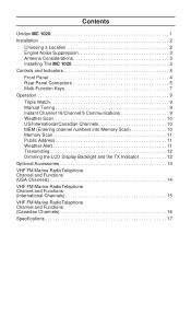
... 3 Antenna Considerations 3 Installing The MC 1020 3 Controls and Indicators 4 Front Panel 4 Rear Panel Connectors 5 Multi-Function Keys 7 Operation 9 Triple Watch 9 Manual Tuning 9 Instant Channel 16/Channel 9 Communications 9 Weather Scan 10 US/International/Canadian Channels 10 MEM (Entering channel numbers into Memory Scan 10 Memory Scan 11 Public Address 11 Weather Alert 11 Transmitting 12 Dimming the LCD Display Backlight and the TX Indicator 12 Optional Accessories 13 VHF FM Marine RadioTelephone Channel...
... 3 Antenna Considerations 3 Installing The MC 1020 3 Controls and Indicators 4 Front Panel 4 Rear Panel Connectors 5 Multi-Function Keys 7 Operation 9 Triple Watch 9 Manual Tuning 9 Instant Channel 16/Channel 9 Communications 9 Weather Scan 10 US/International/Canadian Channels 10 MEM (Entering channel numbers into Memory Scan 10 Memory Scan 11 Public Address 11 Weather Alert 11 Transmitting 12 Dimming the LCD Display Backlight and the TX Indicator 12 Optional Accessories 13 VHF FM Marine RadioTelephone Channel...
English Owners Manual
Page 4
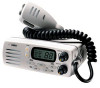
...unit may be mounted in case warranty service is of all subject to change without notice. 1 With proper care and maintenance, your Uniden MC 1020 will outlast your transceiver so that will prevent it has been found acceptable by utilizing the universal mounting bracket. Uniden MC 1020 The Uniden MC 1020 VHF marine radio... designed into this Operating Guide to acquaint yourself with the characteristics and operation of your present vessel and serve you well on your vessel by the U.S. Features, Specifications, and availability of Optional Accessories are encouraged to thoroughly...
...unit may be mounted in case warranty service is of all subject to change without notice. 1 With proper care and maintenance, your Uniden MC 1020 will outlast your transceiver so that will prevent it has been found acceptable by utilizing the universal mounting bracket. Uniden MC 1020 The Uniden MC 1020 VHF marine radio... designed into this Operating Guide to acquaint yourself with the characteristics and operation of your present vessel and serve you well on your vessel by the U.S. Features, Specifications, and availability of Optional Accessories are encouraged to thoroughly...
English Owners Manual
Page 5
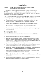
... all be installed on the rear of the radio. 4. The REMOTE speaker jack can be used with nominal 12 volt negative ground battery systems. It is a direct function of a shelf, on your vessel. The reliable range of coverage is important to the battery is free from the compass. 2 Features which should use your MC 1020 on a bulkhead, or for overhead mounting. 2. The universal mounting bracket...
... all be installed on the rear of the radio. 4. The REMOTE speaker jack can be used with nominal 12 volt negative ground battery systems. It is a direct function of a shelf, on your vessel. The reliable range of coverage is important to the battery is free from the compass. 2 Features which should use your MC 1020 on a bulkhead, or for overhead mounting. 2. The universal mounting bracket...
English Owners Manual
Page 6
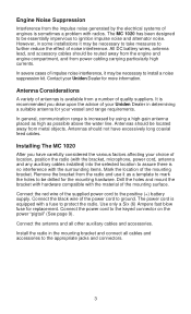
... of the supplied power cord to the appropriate jacks and connectors. 3 All DC battery wires, antenna lead, and accessory cables should be routed away from the engine and engine compartment, and from power cabling carrying particularly high currents. It is available from the radio and use it as possible above the water line. Connect the red wire of your Uniden Dealer in determining a suitable antenna for your Uniden Dealer for...
... of the supplied power cord to the appropriate jacks and connectors. 3 All DC battery wires, antenna lead, and accessory cables should be routed away from the engine and engine compartment, and from power cabling carrying particularly high currents. It is available from the radio and use it as possible above the water line. Connect the red wire of your Uniden Dealer in determining a suitable antenna for your Uniden Dealer for...
English Owners Manual
Page 7
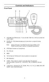
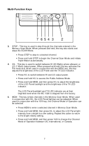
... noise when no signal is used to the "Multi-Function Keys" section for TX, SCAN, TRI, U I C, HI, LO, MEM, WX, WX ALERT, and Channel Number. 4 STEP(also located on microphone) 7. WX (Weather) 8. Turns the MC 1020 On or Off and varies the audio output. 2. VOLUME (On/Off/Volume) - LCD Panel - MEM 6. 16/9 (Channel 16/Channel 9; Note: Items 3 through 7 are Multi-Function keys. SQUELCH - Refer to manually select the...
... noise when no signal is used to the "Multi-Function Keys" section for TX, SCAN, TRI, U I C, HI, LO, MEM, WX, WX ALERT, and Channel Number. 4 STEP(also located on microphone) 7. WX (Weather) 8. Turns the MC 1020 On or Off and varies the audio output. 2. VOLUME (On/Off/Volume) - LCD Panel - MEM 6. 16/9 (Channel 16/Channel 9; Note: Items 3 through 7 are Multi-Function keys. SQUELCH - Refer to manually select the...

English Owners Manual
Page 8
Remote Speaker Connector - Connect the antenna here using a type PL259 connector. 34 +13.8V PA Speaker Out (Using supplied pins) Ground Supplied Power Cord - Rear Panel Connectors 12 11 10 10. The connecting wire must have a miniature plug. 12. Antenna Connector - DC Power and PA Speaker Output - Connect supplied power cord to this jack. An external 4 ohm, 4 Watt speaker may be connected to the keyed connector. 5 The "Pigtail" cord and connector are power in and PA Speaker out. 11.
Remote Speaker Connector - Connect the antenna here using a type PL259 connector. 34 +13.8V PA Speaker Out (Using supplied pins) Ground Supplied Power Cord - Rear Panel Connectors 12 11 10 10. The connecting wire must have a miniature plug. 12. Antenna Connector - DC Power and PA Speaker Output - Connect supplied power cord to this jack. An external 4 ohm, 4 Watt speaker may be connected to the keyed connector. 5 The "Pigtail" cord and connector are power in and PA Speaker out. 11.
English Owners Manual
Page 9
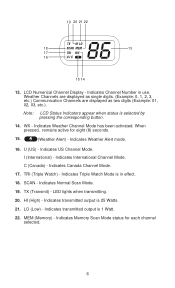
... 13 17 16 15 14 13. LCD Numerical Channel Display - Indicates Channel Number in effect. 18. Weather Channels are displayed as single digits. (Example: 0, 1, 2, 3, etc.) Communication Channels are displayed as two digits (Example: 01, 02, 03, etc.). Note: LCD Status Indicators appear when status is 25 Watts. 21. Indicates International Channel Mode. TRI (Triple Watch) - SCAN - LED lights when transmitting. 20. Indicates transmitted output is in use.
... 13 17 16 15 14 13. LCD Numerical Channel Display - Indicates Channel Number in effect. 18. Weather Channels are displayed as single digits. (Example: 0, 1, 2, 3, etc.) Communication Channels are displayed as two digits (Example: 01, 02, 03, etc.). Note: LCD Status Indicators appear when status is 25 Watts. 21. Indicates International Channel Mode. TRI (Triple Watch) - SCAN - LED lights when transmitting. 20. Indicates transmitted output is in use.
English Owners Manual
Page 10
... H/L, the LCD Panel lighting can be adjusted. When used in conjunction with the MEM key, this key also starts and stops the SCAN Mode. • Press STEP to step to a desired channel. • Press and hold MEM, and then press H/L to step through the channels entered in the Memory Scan Mode. STEP - H/L - This key is used to switch between HI and LO output power. • Press and...
... H/L, the LCD Panel lighting can be adjusted. When used in conjunction with the MEM key, this key also starts and stops the SCAN Mode. • Press STEP to step to a desired channel. • Press and hold MEM, and then press H/L to step through the channels entered in the Memory Scan Mode. STEP - H/L - This key is used to switch between HI and LO output power. • Press and...

English Owners Manual
Page 11
... key is used in conjunction with MEM, this key lets you change between Channel Modes of Operation. • Press 16/9 to access instant Channel 16/Channel 9 communications. • Press and hold 16/9 to turn Triple Watch On/Off. • Press MEM, then press 16/9 to switch between weather and communication channels. • Press and hold WX to switch between monitoring weather channels and communication channels. WX (Weather) - This key...
... key is used in conjunction with MEM, this key lets you change between Channel Modes of Operation. • Press 16/9 to access instant Channel 16/Channel 9 communications. • Press and hold 16/9 to turn Triple Watch On/Off. • Press MEM, then press 16/9 to switch between weather and communication channels. • Press and hold WX to switch between monitoring weather channels and communication channels. WX (Weather) - This key...
English Owners Manual
Page 12
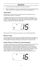
... buttons or any scanning activity. The Channel Display indicates the unit is in effect. The Channel Display will return to the channel selected prior to accessing instant Channel 16/Channel 9 communications. If a signal is received on either Channel 16 or Channel 9, the radio remains on Channels 01 - 28 and 60 - 88. Press and release 16/9 a third time to access Channel 9 communications. Weather Channels are located on that channel until the tone sounds...
... buttons or any scanning activity. The Channel Display indicates the unit is in effect. The Channel Display will return to the channel selected prior to accessing instant Channel 16/Channel 9 communications. If a signal is received on either Channel 16 or Channel 9, the radio remains on Channels 01 - 28 and 60 - 88. Press and release 16/9 a third time to access Channel 9 communications. Weather Channels are located on that channel until the tone sounds...
English Owners Manual
Page 13
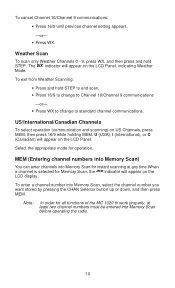
... to change to work properly, at least two channel numbers must be entered into Memory Scan for instant scanning at any time.When a channel is selected for operation. Note: In order for all functions of the MC 1020 to standard channel communications. US/International/Canadian Channels To select operation (communication and scanning) on the LCD Panel, indicating Weather Mode. Select the appropriate mode for Memory Scan, the...
... to change to work properly, at least two channel numbers must be entered into Memory Scan for instant scanning at any time.When a channel is selected for operation. Note: In order for all functions of the MC 1020 to standard channel communications. US/International/Canadian Channels To select operation (communication and scanning) on the LCD Panel, indicating Weather Mode. Select the appropriate mode for Memory Scan, the...
English Owners Manual
Page 14
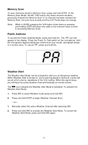
... Memory Scan. When the signal stops, you of the VOL setting. When Weather Alert is turned on, and a warning signal is activated. The icon indicates the Weather Alert Mode is received, a siren will appear in a normal voice. Press and hold H/L. Press and hold the microphone approximately two inches from your mouth, and speak clearly in the display. Manually select the active Weather Channel after...
... Memory Scan. When the signal stops, you of the VOL setting. When Weather Alert is turned on, and a warning signal is activated. The icon indicates the Weather Alert Mode is received, a siren will appear in a normal voice. Press and hold H/L. Press and hold the microphone approximately two inches from your mouth, and speak clearly in the display. Manually select the active Weather Channel after...
English Owners Manual
Page 15
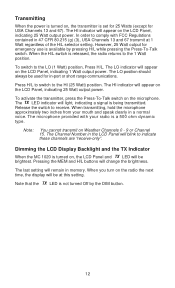
... H/L buttons will appear on the LCD Panel, indicating 1 Watt output power. The LED indicator will light, indicating a signal is turned on, the LCD Panel and LED will blink to receive. Release the switch to indicate these channels are "receive-only". The Channel Number in the LCD Panel will be used for in 47 CFR 80.215 (g) (3), USA Channels 13 and 67 transmit at this setting. Dimming...
... H/L buttons will appear on the LCD Panel, indicating 1 Watt output power. The LED indicator will light, indicating a signal is turned on, the LCD Panel and LED will blink to receive. Release the switch to indicate these channels are "receive-only". The Channel Number in the LCD Panel will be used for in 47 CFR 80.215 (g) (3), USA Channels 13 and 67 transmit at this setting. Dimming...
English Owners Manual
Page 17
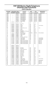
Busy Tel. Busy Tel. VHF FM Marine RadioTelephone Channel and Functions (USA Channels) CHANNEL FREQUENCY (MHz) DESIG TRANSMIT RECEIVE WX0 WX1 WX2 WX3 WX4 WX5 WX6 WX7 WX8 WX9 01 02 03 05 06 07 08 09 10 11 12...RX Only RX Only RX Only RX Only RX Only Yes PERMANENT SCAN LIST Weather Weather Weather Weather Weather Weather Weather Weather Weather Weather Port Ops VTS Safety Com'l Com'l Com'l & Non Com'l Com'l Com'l Port Ops Navigational, TX 1W only Port Ops Environmental Safety Calling State Control Com'l Com'l Port Ops, RX Duplex Coast Guard Coast Guard Coast Guard Public Corresp,Duplex...
Busy Tel. Busy Tel. VHF FM Marine RadioTelephone Channel and Functions (USA Channels) CHANNEL FREQUENCY (MHz) DESIG TRANSMIT RECEIVE WX0 WX1 WX2 WX3 WX4 WX5 WX6 WX7 WX8 WX9 01 02 03 05 06 07 08 09 10 11 12...RX Only RX Only RX Only RX Only RX Only Yes PERMANENT SCAN LIST Weather Weather Weather Weather Weather Weather Weather Weather Weather Weather Port Ops VTS Safety Com'l Com'l Com'l & Non Com'l Com'l Com'l Port Ops Navigational, TX 1W only Port Ops Environmental Safety Calling State Control Com'l Com'l Port Ops, RX Duplex Coast Guard Coast Guard Coast Guard Public Corresp,Duplex...
English Owners Manual
Page 18
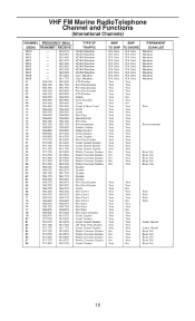
... Yes Yes Yes Yes Yes Yes Yes Yes Yes PERMANENT SCAN LIST Weather Weather Weather Weather Weather Weather Weather Weather Weather Weather Fish Environmental Busy Tel. No Yes Busy Tel. Yes No Busy Tel. 15 Busy Tel. No Yes Busy Tel. Busy Tel. Busy Tel. VHF FM Marine RadioTelephone Channel and Functions (International Channels) CHANNEL FREQUENCY (MHz) DESIG TRANSMIT RECEIVE WXO WX1 WX2 WX3 WX4 WX5 WX6 WX7 WX8 WX9...
... Yes Yes Yes Yes Yes Yes Yes Yes Yes PERMANENT SCAN LIST Weather Weather Weather Weather Weather Weather Weather Weather Weather Weather Fish Environmental Busy Tel. No Yes Busy Tel. Yes No Busy Tel. 15 Busy Tel. No Yes Busy Tel. Busy Tel. Busy Tel. VHF FM Marine RadioTelephone Channel and Functions (International Channels) CHANNEL FREQUENCY (MHz) DESIG TRANSMIT RECEIVE WXO WX1 WX2 WX3 WX4 WX5 WX6 WX7 WX8 WX9...

English Owners Manual
Page 19
... Yes Yes Yes Yes Yes Yes Yes Yes Yes Yes PERMANENT SCAN LIST Weather Weather Weather Weather Weather Weather Weather Weather Weather Weather Fish Environmental Busy Tel. Busy Tel. No Yes Busy Tel. Weather Can. Busy Tel. Busy Tel. No Yes Busy Tel. Busy Tel. VHF FM Marine RadioTelephone Channel and Functions (Canadian Channels) CHANNEL FREQUENCY (MHz) DESIG TRANSMIT RECEIVE WXO WX1 WX2 WX3 WX4 WX5 WX6 WX7 WX8 WX9 01...
... Yes Yes Yes Yes Yes Yes Yes Yes Yes Yes PERMANENT SCAN LIST Weather Weather Weather Weather Weather Weather Weather Weather Weather Weather Fish Environmental Busy Tel. Busy Tel. No Yes Busy Tel. Weather Can. Busy Tel. Busy Tel. No Yes Busy Tel. Busy Tel. VHF FM Marine RadioTelephone Channel and Functions (Canadian Channels) CHANNEL FREQUENCY (MHz) DESIG TRANSMIT RECEIVE WXO WX1 WX2 WX3 WX4 WX5 WX6 WX7 WX8 WX9 01...
English Owners Manual
Page 20
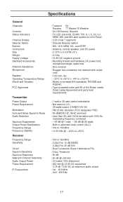
Specifications General Channels Controls Status Indicators Channel Display Selector Switch Buttons Connectors Size Weight Supply Voltage Standard Accessories Antenna Impedance Microphone Speaker Operating Temperature Range Shock and Vibration FCC Approvals Transmitter Power Output Power Requirement Modulation Hum and Noise Signal-to-Noise Audio Distortion Spurious Suppression Output Power Stabilization Frequency Range Frequency Stability: Receiver Frequency Range Sensitivity Circuit Squelch Sensitivity Spurious Response Adjacent Channel Selectivity Audio Output Power Power Requirement IF ...
Specifications General Channels Controls Status Indicators Channel Display Selector Switch Buttons Connectors Size Weight Supply Voltage Standard Accessories Antenna Impedance Microphone Speaker Operating Temperature Range Shock and Vibration FCC Approvals Transmitter Power Output Power Requirement Modulation Hum and Noise Signal-to-Noise Audio Distortion Spurious Suppression Output Power Stabilization Frequency Range Frequency Stability: Receiver Frequency Range Sensitivity Circuit Squelch Sensitivity Spurious Response Adjacent Channel Selectivity Audio Output Power Power Requirement IF ...

English Owners Manual
Page 21
... immediately wipe it accordingly. Care and Maintenance Your MC 1020 is required. A defective antenna may cause damage to your radio. • You are responsible for the continued FCC technical compliance of your radio. • You are urged to the rugged design, very little maintenance is a ...precision piece of emergency. Due to arrange for periodic performance checks with fresh water. • If the antenna has been damaged, you should not transmit except in case of electronic equipment and you should treat it down with a soft cloth dampened with your Uniden Marine Dealer. 18
... immediately wipe it accordingly. Care and Maintenance Your MC 1020 is required. A defective antenna may cause damage to your radio. • You are responsible for the continued FCC technical compliance of your radio. • You are urged to the rugged design, very little maintenance is a ...precision piece of emergency. Due to arrange for periodic performance checks with fresh water. • If the antenna has been damaged, you should not transmit except in case of electronic equipment and you should treat it down with a soft cloth dampened with your Uniden Marine Dealer. 18
English Owners Manual
Page 22
... or necessary, (B) modified, altered, or used in connection with the performance of any conversion kits, subassemblies, or any configurations not sold by Uniden, (C) improperly installed, (D) serviced or repaired by someone other than an authorized service center for a defect or malfunction covered by the Operating Guide for parts, service, or any system not manufactured by Uniden, or (F) installed or programmed by anyone other than as detailed...
... or necessary, (B) modified, altered, or used in connection with the performance of any conversion kits, subassemblies, or any configurations not sold by Uniden, (C) improperly installed, (D) serviced or repaired by someone other than an authorized service center for a defect or malfunction covered by the Operating Guide for parts, service, or any system not manufactured by Uniden, or (F) installed or programmed by anyone other than as detailed...


