Maintenance Manual
Page 3
... a short circuit, which could result in death or serious bodily injury if the safety instruction is not observed. Toshiba requires service technicians and authorized dealers or service providers to ensure the following safety precautions are intended to as shown...overheating, smoke or fire. ‰ If you replace the battery pack or RTC battery, be italicized and identified as the Satellite A110/Satellite Pro A110 Series in this manual to bring important information to your attention. Satellite A110/Satellite Pro A110 Series Maintenance Manual [CONFIDENTIAL] iii CAUTION: "Caution...
... a short circuit, which could result in death or serious bodily injury if the safety instruction is not observed. Toshiba requires service technicians and authorized dealers or service providers to ensure the following safety precautions are intended to as shown...overheating, smoke or fire. ‰ If you replace the battery pack or RTC battery, be italicized and identified as the Satellite A110/Satellite Pro A110 Series in this manual to bring important information to your attention. Satellite A110/Satellite Pro A110 Series Maintenance Manual [CONFIDENTIAL] iii CAUTION: "Caution...
Maintenance Manual
Page 9
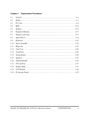
Chapter 4 Replacement Procedures 4.1 General...4-1 4.2 Battery...4-7 4.3 PC Card...4-8 4.4 HDD...4-10 4.5 Modem ...4-12 4.6 Expansion Memory...4-13 4.7 Wireless LAN Unit ...4-15 4.8 Optical Drive...4-18 4.9 Keyboard...4-20 4.10 Direct Assembly...4-22 4.11 Bluetooth...4-25 4.12 Top Cover ...4-26 4.13 Touch Pad ...4-28 4.14 System Board ...4-29 4.15 Speakers ...4-31 4.16 Thermal Module...4-32 4.17 CPU and Fan ...4-33 4.18 Display Mask ...4-35 4.19 LCD Module ...4-36 4.20 FL Inverter Board ...4-38 Satellite A110/Satellite Pro A110 Series Maintenance Manual [CONFIDENTIAL] ix
Chapter 4 Replacement Procedures 4.1 General...4-1 4.2 Battery...4-7 4.3 PC Card...4-8 4.4 HDD...4-10 4.5 Modem ...4-12 4.6 Expansion Memory...4-13 4.7 Wireless LAN Unit ...4-15 4.8 Optical Drive...4-18 4.9 Keyboard...4-20 4.10 Direct Assembly...4-22 4.11 Bluetooth...4-25 4.12 Top Cover ...4-26 4.13 Touch Pad ...4-28 4.14 System Board ...4-29 4.15 Speakers ...4-31 4.16 Thermal Module...4-32 4.17 CPU and Fan ...4-33 4.18 Display Mask ...4-35 4.19 LCD Module ...4-36 4.20 FL Inverter Board ...4-38 Satellite A110/Satellite Pro A110 Series Maintenance Manual [CONFIDENTIAL] ix
Maintenance Manual
Page 40
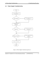
Y es Check power supply connections (Procedure 3) No Replace adaptor / battery (Procedure 2) Can you turn the computer on? No Are the internal power connections secure? Y es Replace system board Y es Run diagnostic program (Procedure 4) Perform internal connection No check (Procedure 5) END Figure 2-2 Power Supply Troubleshooting Process Satellite A110 /Satellite Pro A110 Series Maintenance Manual [CONFIDENTIAL] 2-7 2.3 Power Supply Troubleshooting 2.3 Power...
Y es Check power supply connections (Procedure 3) No Replace adaptor / battery (Procedure 2) Can you turn the computer on? No Are the internal power connections secure? Y es Replace system board Y es Run diagnostic program (Procedure 4) Perform internal connection No check (Procedure 5) END Figure 2-2 Power Supply Troubleshooting Process Satellite A110 /Satellite Pro A110 Series Maintenance Manual [CONFIDENTIAL] 2-7 2.3 Power Supply Troubleshooting 2.3 Power...
Maintenance Manual
Page 41
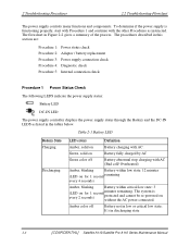
... status check Procedure 2: Adaptor / battery replacement Procedure 3: Power supply connection check Procedure 4: Diagnostic check Procedure 5: Internal connection check Procedure 1 Power Status Check The following LEDS indicate the power supply status: Battery LED DC-IN LED The power...in discharging state 2-8 [CONFIDENTIAL] Satellite A110/Satellite Pro A110 Series Maintenance Manual Green, solid on for 1 second remaining every 4 seconds) Amber, blinking Battery within critical low state: 3 (LED on Battery fully charged by AC Green color off Battery not in the tables below....
... status check Procedure 2: Adaptor / battery replacement Procedure 3: Power supply connection check Procedure 4: Diagnostic check Procedure 5: Internal connection check Procedure 1 Power Status Check The following LEDS indicate the power supply status: Battery LED DC-IN LED The power...in discharging state 2-8 [CONFIDENTIAL] Satellite A110/Satellite Pro A110 Series Maintenance Manual Green, solid on for 1 second remaining every 4 seconds) Amber, blinking Battery within critical low state: 3 (LED on Battery fully charged by AC Green color off Battery not in the tables below....

Maintenance Manual
Page 42
... / battery replacement A faulty adaptor may not supply power or may not charge the battery. To check the power supply status, install a battery pack and connect an AC adaptor to the DC-IN port on Off Table 2-2 DC-IN LED Power supply status AC power exists (LED is not lit, go to Procedure 2. Satellite A110 /Satellite Pro A110 Series...
... / battery replacement A faulty adaptor may not supply power or may not charge the battery. To check the power supply status, install a battery pack and connect an AC adaptor to the DC-IN port on Off Table 2-2 DC-IN LED Power supply status AC power exists (LED is not lit, go to Procedure 2. Satellite A110 /Satellite Pro A110 Series...

Maintenance Manual
Page 44
...not blown, go to Check 2. Replace it is connected firmly, go to Check 3. Satellite A110 /Satellite Pro A110 Series Maintenance Manual [CONFIDENTIAL] 2-11 Disassemble the computer following procedures: 1. If a fuse is blown, go to make sure that the battery cable is functioning normally. Check the...Procedure 4 Diagnostic check The power supply may be disconnected or damaged. If no problem is detected, the battery is firmly connected to Check 3. Procedure 5 Replacement check The system board may be damaged. If it with a new one following the procedures described in ...
...not blown, go to Check 2. Replace it is connected firmly, go to Check 3. Satellite A110 /Satellite Pro A110 Series Maintenance Manual [CONFIDENTIAL] 2-11 Disassemble the computer following procedures: 1. If a fuse is blown, go to make sure that the battery cable is functioning normally. Check the...Procedure 4 Diagnostic check The power supply may be disconnected or damaged. If no problem is detected, the battery is firmly connected to Check 3. Procedure 5 Replacement check The system board may be damaged. If it with a new one following the procedures described in ...
Maintenance Manual
Page 102
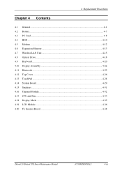
4 Replacement Procedures Chapter 4 Contents 4.1 General...4-1 4.2 Battery...4-7 4.3 PC Card...4-8 4.4 HDD...4-10 4.5 Modem ...4-12 4.6 Expansion Memory 4-13 4.7 Wireless LAN Unit 4-15 4.8 Optical Drive...4-18 4.9 Keyboard...4-20 4.10 Display Assembly ...4-22 4.11 Bluetooth...4-25 4.12 Top Cover ...4-26 4.13 TouchPad ...4-28 4.14 System Board ...4-29 4.15 Speakers ...4-31 4.16 Thermal Module...4-32 4.17 CPU and Fan ...4-33 4.18 Display Mask ...4-35 4.19 LCD Module ...4-36 4.20 FL Inverter Board ...4-38 Detroit 20 /Detroit 20E Series Maintenance Manual [CONFIDENTIAL] 4-iii
4 Replacement Procedures Chapter 4 Contents 4.1 General...4-1 4.2 Battery...4-7 4.3 PC Card...4-8 4.4 HDD...4-10 4.5 Modem ...4-12 4.6 Expansion Memory 4-13 4.7 Wireless LAN Unit 4-15 4.8 Optical Drive...4-18 4.9 Keyboard...4-20 4.10 Display Assembly ...4-22 4.11 Bluetooth...4-25 4.12 Top Cover ...4-26 4.13 TouchPad ...4-28 4.14 System Board ...4-29 4.15 Speakers ...4-31 4.16 Thermal Module...4-32 4.17 CPU and Fan ...4-33 4.18 Display Mask ...4-35 4.19 LCD Module ...4-36 4.20 FL Inverter Board ...4-38 Detroit 20 /Detroit 20E Series Maintenance Manual [CONFIDENTIAL] 4-iii
Maintenance Manual
Page 103
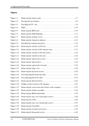
4 Replacement Procedures Figures Figure 4-1 Figure 4-2 Figure 4-3 Figure 4-4 Figure 4-5 Figure 4-6 Figure 4-7 Figure 4-8 Figure 4-9 Figure 4-10 Figure 4-11 Figure 4-12 Figure 4-13 Figure 4-14 Figure 4-15 Figure 4-16 ... 4-20 Figure 4-21 Figure 4-22 Figure 4-23 Figure 4-24 Figure 4-25 Figure 4-26 Figure 4-27 Figure 4-28 Figure 4-29 Figure 4-30 Figure 4-31 Removing the battery pack 4-7 Pressing the eject button 4-8 Installing the PC card 4-9 HDD ...4-10 Removing the HDD unit 4-10 Removing the EMI Shielding 4-11 Removing the modem screws...
4 Replacement Procedures Figures Figure 4-1 Figure 4-2 Figure 4-3 Figure 4-4 Figure 4-5 Figure 4-6 Figure 4-7 Figure 4-8 Figure 4-9 Figure 4-10 Figure 4-11 Figure 4-12 Figure 4-13 Figure 4-14 Figure 4-15 Figure 4-16 ... 4-20 Figure 4-21 Figure 4-22 Figure 4-23 Figure 4-24 Figure 4-25 Figure 4-26 Figure 4-27 Figure 4-28 Figure 4-29 Figure 4-30 Figure 4-31 Removing the battery pack 4-7 Pressing the eject button 4-8 Installing the PC card 4-9 HDD ...4-10 Removing the HDD unit 4-10 Removing the EMI Shielding 4-11 Removing the modem screws...
Maintenance Manual
Page 106
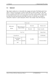
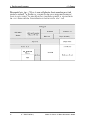
... 4.1 General This chapter explains how to the example on the following page. Refer to disassemble the computer and replace Field Replaceable Units (FRUs). Always start by removing the battery pack, next, optional items such as the optional PC Card, then follow the chart downward removing only those FRUs necessary to ...reach the one . It may not be removed in order to replace one you think is a guide to which FRUs need...
... 4.1 General This chapter explains how to the example on the following page. Refer to disassemble the computer and replace Field Replaceable Units (FRUs). Always start by removing the battery pack, next, optional items such as the optional PC Card, then follow the chart downward removing only those FRUs necessary to ...reach the one . It may not be removed in order to replace one you think is a guide to which FRUs need...
Maintenance Manual
Page 107
...HDD and/or Modem Battery pack ODD and Expansion Memory Module Keyboard Bluetooth Top Cover System Board Fan & Thermal Module CPU Speakers TouchPad Wireless LAN Display Assembly Display Mask LCD Module FL Inverter Board 4-2 [CONFIDENTIAL] Detroit 20 /Detroit 20E Series Maintenance Manual 4 Replacement Procedures 4.1 General The... process by the top cover that must be removed before the Speakers can be removed and repaired or replaced. The Speakers are overlapped by removing the battery pack. The removable keyboard and display assembly in turn overlap the top cover.
...HDD and/or Modem Battery pack ODD and Expansion Memory Module Keyboard Bluetooth Top Cover System Board Fan & Thermal Module CPU Speakers TouchPad Wireless LAN Display Assembly Display Mask LCD Module FL Inverter Board 4-2 [CONFIDENTIAL] Detroit 20 /Detroit 20E Series Maintenance Manual 4 Replacement Procedures 4.1 General The... process by the top cover that must be removed before the Speakers can be removed and repaired or replaced. The Speakers are overlapped by removing the battery pack. The removable keyboard and display assembly in turn overlap the top cover.

Maintenance Manual
Page 108
... component have different specifications, they may burst or explode. When you change a component, be very careful not to use the lithium ion battery pack or backup battery that is disconnected from the power source. 2. circuit, fire, or other components carry high voltages. The power supply, FL inverter, and... all screws are listed in place. Always turn on the power of electrical shock even when the computer is authorized by Toshiba. Make sure that all replacement components meet the specifications for the computer and that came with the computer or one recommended by...
... component have different specifications, they may burst or explode. When you change a component, be very careful not to use the lithium ion battery pack or backup battery that is disconnected from the power source. 2. circuit, fire, or other components carry high voltages. The power supply, FL inverter, and... all screws are listed in place. Always turn on the power of electrical shock even when the computer is authorized by Toshiba. Make sure that all replacement components meet the specifications for the computer and that came with the computer or one recommended by...

Maintenance Manual
Page 109
... Dust and contaminates ‰ Static electricity ‰ Extreme heat, cold, and humidity 4. Make sure the FRU you have fixed or replaced. 4-4 [CONFIDENTIAL] Detroit 20 /Detroit 20E Series Maintenance Manual Screw sizes are placed in a safe place and identified with the disassembly ...listed in their corresponding figures. 9. The computer contains many screws when you are replacing is functioning properly by removing the AC adaptor and the battery pack as instructed in section 4.2. 1. 4 Replacement Procedures 4.1 General Before You Begin Look over the procedures in this manual. ...
... Dust and contaminates ‰ Static electricity ‰ Extreme heat, cold, and humidity 4. Make sure the FRU you have fixed or replaced. 4-4 [CONFIDENTIAL] Detroit 20 /Detroit 20E Series Maintenance Manual Screw sizes are placed in a safe place and identified with the disassembly ...listed in their corresponding figures. 9. The computer contains many screws when you are replacing is functioning properly by removing the AC adaptor and the battery pack as instructed in section 4.2. 1. 4 Replacement Procedures 4.1 General Before You Begin Look over the procedures in this manual. ...

Maintenance Manual
Page 112
... batteries recommended by Toshiba as replacements. 1. Then you can explode if not properly replaced, used, handled or disposed of. The battery bay latch clicks into the battery bay. Turn the computer upside down. 2. WARNING: The battery is a lithium ion battery and can remove it from the battery bay, follow the steps below : 1. 4.2 Battery 4 Replacement Procedures 4.2 Battery Removing the Battery Pack To remove the battery...
... batteries recommended by Toshiba as replacements. 1. Then you can explode if not properly replaced, used, handled or disposed of. The battery bay latch clicks into the battery bay. Turn the computer upside down. 2. WARNING: The battery is a lithium ion battery and can remove it from the battery bay, follow the steps below : 1. 4.2 Battery 4 Replacement Procedures 4.2 Battery Removing the Battery Pack To remove the battery...
Maintenance Manual
Page 131
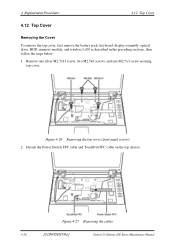
...] Detroit 20 /Detroit 20E Series Maintenance Manual Figure 4-26 Removing the top cover (front panel screws) 2. 4 Replacement Procedures 4.12 Top Cover 4.12 Top Cover Removing the Cover To remove the top cover, first remove the battery pack, keyboard, display assembly, optical drive, HDD, memory module, and wireless LAN as described in the...
...] Detroit 20 /Detroit 20E Series Maintenance Manual Figure 4-26 Removing the top cover (front panel screws) 2. 4 Replacement Procedures 4.12 Top Cover 4.12 Top Cover Removing the Cover To remove the top cover, first remove the battery pack, keyboard, display assembly, optical drive, HDD, memory module, and wireless LAN as described in the...

Maintenance Manual
Page 143
4 Replacement Procedures 4.20 FL Inverter Board 4.20 FL Inverter Board Removing the FL Inverter Board To remove the FL inverter board, first remove the battery pack, the display assembly, display mask, and LCD module, then follow the steps below : 1. Seat the FL invert board on the LCD cover, then secure ...
4 Replacement Procedures 4.20 FL Inverter Board 4.20 FL Inverter Board Removing the FL Inverter Board To remove the FL inverter board, first remove the battery pack, the display assembly, display mask, and LCD module, then follow the steps below : 1. Seat the FL invert board on the LCD cover, then secure ...


