
Maintenance Manual
Page 8
... 4.15 3G card...4-44 4.16 LAN jack...4-46 4.17 MJ board ...4-47 4.18 RTC battery...4-50 4.19 RGB board ...4-51 4.20 Sensor board...4-53 4.21 Fan/Heat sink ...4-54 4.22 PC card slot ...4-57 4.23 System board and LCD cover assembly 4-58 4.24 LCD mask ...4-61 4.25 LCD unit ...4-63 4.26...
... 4.15 3G card...4-44 4.16 LAN jack...4-46 4.17 MJ board ...4-47 4.18 RTC battery...4-50 4.19 RGB board ...4-51 4.20 Sensor board...4-53 4.21 Fan/Heat sink ...4-54 4.22 PC card slot ...4-57 4.23 System board and LCD cover assembly 4-58 4.24 LCD mask ...4-61 4.25 LCD unit ...4-63 4.26...

Maintenance Manual
Page 35
... EC/KBC NO SD Slot NO SIM Slot(3G) NO Finger Sensor NO WLAN NO SIM Slot(WiMax) NO WLAN NO WLAN NO Finger Sensor PORTEGE R500 Maintenance Manual (960-634) [CONFIDENTIAL] 1-21 1.9 Power Supply 1 Hardware Overview Name P3V P5V PNL-P2V PPV PTV R3V S3V SD-P3V UIMPWR-E3V VDDA-E3V... Yes/NO Yes/NO Yes/NO NO Yes/NO ICH7-M, ODD, HDD(SATA), PC-Card Power, LED, KB, PAD, NO CRT, FAN, LED Backlight、 AN12945A NO LCD NO CPU NO Clock Generator、CPU、GMCH、ICH7-
... EC/KBC NO SD Slot NO SIM Slot(3G) NO Finger Sensor NO WLAN NO SIM Slot(WiMax) NO WLAN NO WLAN NO Finger Sensor PORTEGE R500 Maintenance Manual (960-634) [CONFIDENTIAL] 1-21 1.9 Power Supply 1 Hardware Overview Name P3V P5V PNL-P2V PPV PTV R3V S3V SD-P3V UIMPWR-E3V VDDA-E3V... Yes/NO Yes/NO Yes/NO NO Yes/NO ICH7-M, ODD, HDD(SATA), PC-Card Power, LED, KB, PAD, NO CRT, FAN, LED Backlight、 AN12945A NO LCD NO CPU NO Clock Generator、CPU、GMCH、ICH7-

Maintenance Manual
Page 66
... Board Troubleshooting Table 2-5 Debug port (Boot mode) error status (2/10) D port status Inspection items F00AH Saving key scan code A setup of TASK_1 second_TSC F00BH Controlling fan Initializing sound items (for BEEP) When request BIOS, EC/KBC rewriting Details Permission of system speaker Releasing mute Making the volume max (model that can... root directory. Setting of parameters for 2HD(1.44MB) Reading of first sector, If it is the data of "CHGBIOSA.EXE" and "CHGFIRMA.EXE" 2-20 [CONFIDENTIAL] PORTEGE R500 Maintenance Manual (960-634)
... Board Troubleshooting Table 2-5 Debug port (Boot mode) error status (2/10) D port status Inspection items F00AH Saving key scan code A setup of TASK_1 second_TSC F00BH Controlling fan Initializing sound items (for BEEP) When request BIOS, EC/KBC rewriting Details Permission of system speaker Releasing mute Making the volume max (model that can... root directory. Setting of parameters for 2HD(1.44MB) Reading of first sector, If it is the data of "CHGBIOSA.EXE" and "CHGFIRMA.EXE" 2-20 [CONFIDENTIAL] PORTEGE R500 Maintenance Manual (960-634)

Maintenance Manual
Page 119
Fan ON/OFF 05 - Selecting NO returns the process to execute and press Enter. PORTEGE R500 Maintenance Manual (960-634) [CONFIDENTIAL] 3-7 SYSTEM TEST, the following message will appear: SYSTEM TEST NAME XXXXXX xxxxxxx DIAGNOSTIC TEST VX.XX [Ctrl]+[Break] : test end [...
Fan ON/OFF 05 - Selecting NO returns the process to execute and press Enter. PORTEGE R500 Maintenance Manual (960-634) [CONFIDENTIAL] 3-7 SYSTEM TEST, the following message will appear: SYSTEM TEST NAME XXXXXX xxxxxxx DIAGNOSTIC TEST VX.XX [Ctrl]+[Break] : test end [...

Maintenance Manual
Page 124
... 04 05 01 02 03 04 01 01 02 03 04 05 06 07 08 09 01 02 03 04 05 Subtest Name ROM checksum Fan ON/OFF Geyserville Quick charge DMI read Conventional memory Protected Mode Cache memory (on/off) Stress Pressed key code display VRAM read/write for VGA... LCD Brightness LCD EDID Information External EDID read/compare Sequential read Sequential read/write Random address/data Write specified address Read specified address 3-12 [CONFIDENTIAL] PORTEGE R500 Maintenance Manual (960-634)
... 04 05 01 02 03 04 01 01 02 03 04 05 06 07 08 09 01 02 03 04 05 Subtest Name ROM checksum Fan ON/OFF Geyserville Quick charge DMI read Conventional memory Protected Mode Cache memory (on/off) Stress Pressed key code display VRAM read/write for VGA... LCD Brightness LCD EDID Information External EDID read/compare Sequential read Sequential read/write Random address/data Write specified address Read specified address 3-12 [CONFIDENTIAL] PORTEGE R500 Maintenance Manual (960-634)

Maintenance Manual
Page 126
... operating clock speed can be changed. 3-14 [CONFIDENTIAL] PORTEGE R500 Maintenance Manual (960-634) To check the CPU fan, press 1 and Enter. After a while, the fan rotating will appear. *** Test Fan Revolution High speed Start Make sure the fan rotates at low speed, then press Enter. Fan number select (1;FAN#1(CPU), 2;FAN#2(GPU)*1, 0; The following message will appear. *** Test...
... operating clock speed can be changed. 3-14 [CONFIDENTIAL] PORTEGE R500 Maintenance Manual (960-634) To check the CPU fan, press 1 and Enter. After a while, the fan rotating will appear. *** Test Fan Revolution High speed Start Make sure the fan rotates at low speed, then press Enter. Fan number select (1;FAN#1(CPU), 2;FAN#2(GPU)*1, 0; The following message will appear. *** Test...

Maintenance Manual
Page 205
... on the CPU. When the CPU temperature falls to a normal range, the fan turns off and the processing speed is increased. LCD Brightness Use this option to set the level of LCD brightness. PORTEGE R500 Maintenance Manual (960-634) [CONFIDENTIAL] 3-93 High Low CPU operates at high speed. .... When the CPU temperature falls to cool down the CPU. If the temperature is turned off . If the CPU becomes too hot, the fan turns on . 3.31 BIOS SETUP 3 Tests and Diagnostics Processing Speed This feature changes the CPU processing speed. When the hot condition continues,...
... on the CPU. When the CPU temperature falls to a normal range, the fan turns off and the processing speed is increased. LCD Brightness Use this option to set the level of LCD brightness. PORTEGE R500 Maintenance Manual (960-634) [CONFIDENTIAL] 3-93 High Low CPU operates at high speed. .... When the CPU temperature falls to cool down the CPU. If the temperature is turned off . If the CPU becomes too hot, the fan turns on . 3.31 BIOS SETUP 3 Tests and Diagnostics Processing Speed This feature changes the CPU processing speed. When the hot condition continues,...
Maintenance Manual
Page 213
... memory card ...4-11 4.5 Memory module...4-12 4.6 Base cover assembly 4-15 4.7 PC card slot ...4-18 4.8 Battery lock/Battery latch 4-20 4.9 Wireless LAN card 4-21 4.10 CPU fan assembly...4-23 4.11 RTC battery...4-26 4.12 DC-IN jack...4-28 4.13 Bluetooth module...4-29 4.14 HDD/SSD ...4-31 4.14.1 2.5" HDD 4-32 4.14.2 1.8" HDD 4-33... pad/Fingerprint sensor board 4-54 4.22 Keyboard...4-57 4.23 LCD unit ...4-59 4.24 Wireless LAN antenna/Bluetooth antenna 4-62 4.25 Hinge...4-64 PORTÉGÉ R500 Maintenance Manual (960-634) [CONFIDENTIAL] 4-iii
... memory card ...4-11 4.5 Memory module...4-12 4.6 Base cover assembly 4-15 4.7 PC card slot ...4-18 4.8 Battery lock/Battery latch 4-20 4.9 Wireless LAN card 4-21 4.10 CPU fan assembly...4-23 4.11 RTC battery...4-26 4.12 DC-IN jack...4-28 4.13 Bluetooth module...4-29 4.14 HDD/SSD ...4-31 4.14.1 2.5" HDD 4-32 4.14.2 1.8" HDD 4-33... pad/Fingerprint sensor board 4-54 4.22 Keyboard...4-57 4.23 LCD unit ...4-59 4.24 Wireless LAN antenna/Bluetooth antenna 4-62 4.25 Hinge...4-64 PORTÉGÉ R500 Maintenance Manual (960-634) [CONFIDENTIAL] 4-iii
Maintenance Manual
Page 214
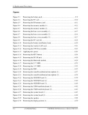
... cover assembly (3 4-17 Removing the PC card slot 4-18 Removing the battery lock/battery latch 4-20 Removing the wireless LAN card 4-21 Removing the CPU Fan assembly 4-23 Applying new grease 4-24 Removing the RTC battery 4-26 Removing the DC-IN jack 4-28 Removing the Bluetooth module 4-29 Removing the 2.5" HDD... (2 4-43 Removing the system board (1 4-45 Removing the system board (2 4-46 Removing the speaker 4-48 Removing the display portion (1 4-50 4-iv [CONFIDENTIAL] PORTÉGÉ R500 Maintenance Manual (960-634)
... cover assembly (3 4-17 Removing the PC card slot 4-18 Removing the battery lock/battery latch 4-20 Removing the wireless LAN card 4-21 Removing the CPU Fan assembly 4-23 Applying new grease 4-24 Removing the RTC battery 4-26 Removing the DC-IN jack 4-28 Removing the Bluetooth module 4-29 Removing the 2.5" HDD... (2 4-43 Removing the system board (1 4-45 Removing the system board (2 4-46 Removing the speaker 4-48 Removing the display portion (1 4-50 4-iv [CONFIDENTIAL] PORTÉGÉ R500 Maintenance Manual (960-634)
Maintenance Manual
Page 239
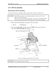
... 2. 4.10 CPU fan assembly 4 Replacement Procedures 4.10 CPU fan assembly Removing the CPU fan assembly To remove the CPU fan assembly, follow the steps below and refer to let it cool before starting repair work. Apply new grease when installing. 1. PORTÉGÉ R500 Maintenance Manual (960-...634) [CONFIDENTIAL] 4-23 M2×6C S-THIN HEAD Fan cable CN8771 CPU Fan assembly Figure 4-12 Removing the CPU Fan assembly CAUTION: Do not apply pressure to the...
... 2. 4.10 CPU fan assembly 4 Replacement Procedures 4.10 CPU fan assembly Removing the CPU fan assembly To remove the CPU fan assembly, follow the steps below and refer to let it cool before starting repair work. Apply new grease when installing. 1. PORTÉGÉ R500 Maintenance Manual (960-...634) [CONFIDENTIAL] 4-23 M2×6C S-THIN HEAD Fan cable CN8771 CPU Fan assembly Figure 4-12 Removing the CPU Fan assembly CAUTION: Do not apply pressure to the...
Maintenance Manual
Page 240
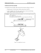
... shall not be over the height of the CPU. 2. CPU OK Chip Figure 4-13 Applying new grease 4-24 [CONFIDENTIAL] PORTÉGÉ R500 Maintenance Manual (960-634) Apply new grease on the CPU chip. Use a spatula to cover the chip surface using a special syringe as shown... in the following figure. 4 Replacement Procedures 4.10 CPU fan assembly Installing the CPU fan assembly To install the CPU fan assembly, follow the steps below and refer to Figure 4-12 and 4-13. 1. Wipe the grease off of the bottom...
... shall not be over the height of the CPU. 2. CPU OK Chip Figure 4-13 Applying new grease 4-24 [CONFIDENTIAL] PORTÉGÉ R500 Maintenance Manual (960-634) Apply new grease on the CPU chip. Use a spatula to cover the chip surface using a special syringe as shown... in the following figure. 4 Replacement Procedures 4.10 CPU fan assembly Installing the CPU fan assembly To install the CPU fan assembly, follow the steps below and refer to Figure 4-12 and 4-13. 1. Wipe the grease off of the bottom...
Maintenance Manual
Page 241
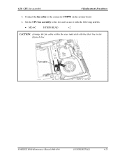
Set the CPU fan assembly to the connector CN8771 on the system board. 4. 4.10 CPU fan assembly 4 Replacement Procedures 3. Connect the fan cable to the slot and secure it with the following screws. • M2×6C S-THIN HEAD ×2 CAUTION: Arrange the fan cable within the area indicated with the thick line in the figure below. Fan cable PORTÉGÉ R500 Maintenance Manual (960-634) [CONFIDENTIAL] 4-25
Set the CPU fan assembly to the connector CN8771 on the system board. 4. 4.10 CPU fan assembly 4 Replacement Procedures 3. Connect the fan cable to the slot and secure it with the following screws. • M2×6C S-THIN HEAD ×2 CAUTION: Arrange the fan cable within the area indicated with the thick line in the figure below. Fan cable PORTÉGÉ R500 Maintenance Manual (960-634) [CONFIDENTIAL] 4-25

Maintenance Manual
Page 289
... C-11 USB (PORT4) interface connector (4-pin C-12 Table C-12 CRT interface connector (15-pin C-12 Table C-13 LCD interface connector (34-pin C-13 Table C-14 FAN interface connector (4-pin C-14 Table C-15 DC-IN connector (4-pin C-14 Table C-16 Battery connector (10-pin C-14 Table C-17 RTC battery connector (3-pin C-14... C-20 Table C-26 Int-Microphone interface connector (2-pin C-20 Table C-27 Speaker interface connector (2-pin C-20 Table C-28 System board interface connector (36-pin C-21 PORTEGE R500 Maintenance Manual (960-634) [CONFIDENTIAL] App-vii
... C-11 USB (PORT4) interface connector (4-pin C-12 Table C-12 CRT interface connector (15-pin C-12 Table C-13 LCD interface connector (34-pin C-13 Table C-14 FAN interface connector (4-pin C-14 Table C-15 DC-IN connector (4-pin C-14 Table C-16 Battery connector (10-pin C-14 Table C-17 RTC battery connector (3-pin C-14... C-20 Table C-26 Int-Microphone interface connector (2-pin C-20 Table C-27 Speaker interface connector (2-pin C-20 Table C-28 System board interface connector (36-pin C-21 PORTEGE R500 Maintenance Manual (960-634) [CONFIDENTIAL] App-vii

Maintenance Manual
Page 302
... Mini PCI Express I/F connector FMU3G* board I/F connector Keyboard I/F connector It is debugging port for development only 1394 I/F connector USB (PORT4) I/F connector CRT I/F connector LCD I/F connector FAN I/F connector DC-IN connector Battery connector RTC battery connector FMUSS* board I/F connector FMUFS* board I/F connector Membrane I/F connector CPU B-4 [CONFIDENTIAL] PORTEGE R500 Maintenance Manual (960-634)
... Mini PCI Express I/F connector FMU3G* board I/F connector Keyboard I/F connector It is debugging port for development only 1394 I/F connector USB (PORT4) I/F connector CRT I/F connector LCD I/F connector FAN I/F connector DC-IN connector Battery connector RTC battery connector FMUSS* board I/F connector FMUFS* board I/F connector Membrane I/F connector CPU B-4 [CONFIDENTIAL] PORTEGE R500 Maintenance Manual (960-634)

User Manual
Page 47
... order to reduce the risk of password security, supervisor and user, are available to prevent unauthorized access to a certain level, the cooling fan is exhausted to -disk contact. This can be caused by head-to the point that , if the computer's internal temperature rises to... your computer. Low battery automatic Hibernation Mode *1 When battery power is turned on using this feature. TOSHIBA HDD Protection This feature uses the acceleration sensor built in the computer to detect vibration and shocks, and automatically moves the hard disk drive...
... order to reduce the risk of password security, supervisor and user, are available to prevent unauthorized access to a certain level, the cooling fan is exhausted to -disk contact. This can be caused by head-to the point that , if the computer's internal temperature rises to... your computer. Low battery automatic Hibernation Mode *1 When battery power is turned on using this feature. TOSHIBA HDD Protection This feature uses the acceleration sensor built in the computer to detect vibration and shocks, and automatically moves the hard disk drive...

User Manual
Page 100
...this temperature by either setting, the computer will be turned off . When the processor's temperature falls to a normal range, the fan will automatically shuts down to the maximum for 10 seconds. in memory will be lost. This function does not work when the computer... When the AC adaptor is disconnected or the lid is disabled. TOSHIBA HDD Protection Message Specify whether to display a message when TOSHIBA HDD Protection is equipped an internal temperature sensor which activates a cooling fan or lowers the processing speed if the computer's internal temperature rises to...
...this temperature by either setting, the computer will be turned off . When the processor's temperature falls to a normal range, the fan will automatically shuts down to the maximum for 10 seconds. in memory will be lost. This function does not work when the computer... When the AC adaptor is disconnected or the lid is disabled. TOSHIBA HDD Protection Message Specify whether to display a message when TOSHIBA HDD Protection is equipped an internal temperature sensor which activates a cooling fan or lowers the processing speed if the computer's internal temperature rises to...


