

User Manual
Page 8
... of disc contents Normally, DVD video discs are divided into titles, and the titles are divided into chapters. Always keep the disc clean. Store discs vertically in places subject to civil and criminal liability. Do not store discs in a case. Stacking or placing objects on the disc cause picture and sound...
... of disc contents Normally, DVD video discs are divided into titles, and the titles are divided into chapters. Always keep the disc clean. Store discs vertically in places subject to civil and criminal liability. Do not store discs in a case. Stacking or placing objects on the disc cause picture and sound...

User Manual
Page 36
... obtain the best possible picture. to protect the video tape against excessive wear. "DIGITAL TRACK" will appear for 4 seconds on the screen. Slow tracking and vertical lock adjustment If noise bars appear in SP. • The audio output is more appropriate as follows: • Press TRK + / - Frame by frame. Playback (VCR...
... obtain the best possible picture. to protect the video tape against excessive wear. "DIGITAL TRACK" will appear for 4 seconds on the screen. Slow tracking and vertical lock adjustment If noise bars appear in SP. • The audio output is more appropriate as follows: • Press TRK + / - Frame by frame. Playback (VCR...

Service Manual
Page 34
... machine. (Refer to Fig. 5-2.) NOTE Do not rotate or move the IC back and forth , until IC can move the Braided Shield Wire in the vertical direction towards the IC pattern. Absorb the solder left on all the parts located within 10 mm distance from any damage. (Refer to Fig. 5-1.) NOTE...
... machine. (Refer to Fig. 5-2.) NOTE Do not rotate or move the IC back and forth , until IC can move the Braided Shield Wire in the vertical direction towards the IC pattern. Absorb the solder left on all the parts located within 10 mm distance from any damage. (Refer to Fig. 5-1.) NOTE...
Service Manual
Page 37
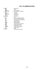
S STB SW SYNC SYNC SEP T TR TRAC TRICK PB TP U UNREG VV VCO VIF VP V.PB VR V.REC VSF VSR VSS V-SYNC VT X X'TAL Y Y/C KEY TO ABBREVIATIONS : Serial Strobe : Switch : Synchronization : Sync Separator, Separation : Transistor : Tracking : Trick Playback : Test Point : Unregulated : Volt : Voltage Controlled Oscillator : Video Intermediate Frequency : Vertical Pulse, Voltage Display : Video Playback : Variable Resistor : Video Recording : Visual Search Fast Forward : Visual Search Rewind : Voltage Super Source : Vertical-Synchronization : Voltage Tuning : Crystal : Luminance/Chrominance C1-2
S STB SW SYNC SYNC SEP T TR TRAC TRICK PB TP U UNREG VV VCO VIF VP V.PB VR V.REC VSF VSR VSS V-SYNC VT X X'TAL Y Y/C KEY TO ABBREVIATIONS : Serial Strobe : Switch : Synchronization : Sync Separator, Separation : Transistor : Tracking : Trick Playback : Test Point : Unregulated : Volt : Voltage Controlled Oscillator : Video Intermediate Frequency : Vertical Pulse, Voltage Display : Video Playback : Variable Resistor : Video Recording : Visual Search Fast Forward : Visual Search Rewind : Voltage Super Source : Vertical-Synchronization : Voltage Tuning : Crystal : Luminance/Chrominance C1-2
Service Manual
Page 48
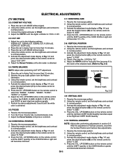
...BIAS=127, G.BIAS=127, B.BIAS=127, R.DRV=63, G.DRV=07, B.DRV=63, 2. Activate the adjustment mode display of Vertical Linearity, reconfirm the Vertical Position and Vertical Size adjustments. 1. Receive the monoscope pattern. 2. Check if the step No. V.POSI is achieved. 2-5: FOCUS 1. Receive the ...on upside and downside becomes minimum. Turn the Focus Volume fully counterclockwise once. 3. horizontal line Notch Shadow mask Fig. 2-2 2-9: VERTICAL SIZE 1. Using the remote control, set the brightness and contrast to normal position. 3. Connect the digital voltmeter to the following...
...BIAS=127, G.BIAS=127, B.BIAS=127, R.DRV=63, G.DRV=07, B.DRV=63, 2. Activate the adjustment mode display of Vertical Linearity, reconfirm the Vertical Position and Vertical Size adjustments. 1. Receive the monoscope pattern. 2. Check if the step No. V.POSI is achieved. 2-5: FOCUS 1. Receive the ...on upside and downside becomes minimum. Turn the Focus Volume fully counterclockwise once. 3. horizontal line Notch Shadow mask Fig. 2-2 2-9: VERTICAL SIZE 1. Using the remote control, set the brightness and contrast to normal position. 3. Connect the digital voltmeter to the following...

Service Manual
Page 49
... (RF Input) 2. Using the remote control, set to Fig. 2-4). 6. Press the INPUT button on the remote control until the right and left vertical lines are straight. 2-14: CORNER CORR BOTTOM 1. UP/DOWN button on the remote control to set the brightness and contrast to normal position. 3. ...Fig. 1-1 and 9. UP/DOWN button on the remote control to normal position. 3. UP/DOWN button on the remote control until the both ends vertical lines are straight. 2-16: BRIGHT CENTER 1. Receive the crosshatch signal from the Pattern Generator. 2. UP/DOWN button on the remote control until ...
... (RF Input) 2. Using the remote control, set to Fig. 2-4). 6. Press the INPUT button on the remote control until the right and left vertical lines are straight. 2-14: CORNER CORR BOTTOM 1. UP/DOWN button on the remote control to set the brightness and contrast to normal position. 3. ...Fig. 1-1 and 9. UP/DOWN button on the remote control to normal position. 3. UP/DOWN button on the remote control until the both ends vertical lines are straight. 2-16: BRIGHT CENTER 1. Receive the crosshatch signal from the Pattern Generator. 2. UP/DOWN button on the remote control until ...
