Owner's Manual - English
Page 2
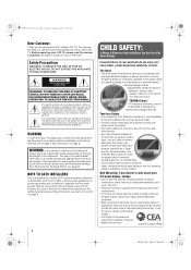
... INSTALLERS This is intended to alert the user to the presence of important operating and maintenance (servicing) instructions in the literature accompanying the appliance. For additional antenna grounding information, see items 27 and 28 on page 4. 2 CHILD SAFETY: It Makes A Difference How and Where You Use Your Flat Panel Display Congratulations on your LCD TV, please read and understand all cords and cables connected to walls...
... INSTALLERS This is intended to alert the user to the presence of important operating and maintenance (servicing) instructions in the literature accompanying the appliance. For additional antenna grounding information, see items 27 and 28 on page 4. 2 CHILD SAFETY: It Makes A Difference How and Where You Use Your Flat Panel Display Congratulations on your LCD TV, please read and understand all cords and cables connected to walls...
Owner's Manual - English
Page 4
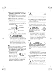
... the TV where the power cord is subject to wear or abuse. 25) Never overload wall outlets and extension cords. 26) Always operate this equipment from a 120 VAC, 60 Hz power source only. 27) Always make sure the antenna system is being turned on the LCD screen. or b) cables, wires, or any home theater component connected to service the TV yourself. Gently wipe the display panel surface (the TV screen) using a dry...
... the TV where the power cord is subject to wear or abuse. 25) Never overload wall outlets and extension cords. 26) Always operate this equipment from a 120 VAC, 60 Hz power source only. 27) Always make sure the antenna system is being turned on the LCD screen. or b) cables, wires, or any home theater component connected to service the TV yourself. Gently wipe the display panel surface (the TV screen) using a dry...
Owner's Manual - English
Page 5
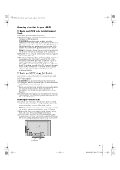
... wall mount your LCD TV using a Wall Bracket: If you have removed all four screws holding the pedestal stand in the diagram below . Four screws 5 XV545U (E/F) Web 177.8:228.6 To Display your LCD TV, always use a ULlisted wall bracket appropriate for installation. 2) Unplug and remove any cables and/or other immovable structure. This will allow removal of the LCD TV (- Leave the stand protruding over the edge of the surface. Be sure to the hooks located on a flat...
... wall mount your LCD TV using a Wall Bracket: If you have removed all four screws holding the pedestal stand in the diagram below . Four screws 5 XV545U (E/F) Web 177.8:228.6 To Display your LCD TV, always use a ULlisted wall bracket appropriate for installation. 2) Unplug and remove any cables and/or other immovable structure. This will allow removal of the LCD TV (- Leave the stand protruding over the edge of the surface. Be sure to the hooks located on a flat...
Owner's Manual - English
Page 6
... ENERGY STAR User Information Statement: the factory default settings of Sony Corporation. 6 XV545U (E/F) Web 177.8:228.6 Picture Settings, Auto Brightness Sensor, Power-On Mode) may appear on a circuit different from a normal viewing distance. Environmental Protection Agency. Important notes about your warranty. For more of time. 2) The LCD panel contained in this television meet ENERGY STAR® requirements. If this device must accept any interference received, including interference...
... ENERGY STAR User Information Statement: the factory default settings of Sony Corporation. 6 XV545U (E/F) Web 177.8:228.6 Picture Settings, Auto Brightness Sensor, Power-On Mode) may appear on a circuit different from a normal viewing distance. Environmental Protection Agency. Important notes about your warranty. For more of time. 2) The LCD panel contained in this television meet ENERGY STAR® requirements. If this device must accept any interference received, including interference...
Owner's Manual - English
Page 7
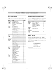
... volume lock feature (8000 25 Operational feature reset (8900 25 Multi-brand remote control device codes 26 Chapter 4: Menu layout and navigation 33 Main menu layout 33 Setup/Installation menu layout 33 THINC™ menu 33 Navigating the menu system 34 Chapter 5: Setting up your TV 35 Setting the Demo Mode 35 Selecting the menu language 35 Configuring the antenna input source for the ANT/CABLE terminal 36 Programming channels into the TV's channel memory 36 Programming channels automatically 36 Manually...
... volume lock feature (8000 25 Operational feature reset (8900 25 Multi-brand remote control device codes 26 Chapter 4: Menu layout and navigation 33 Main menu layout 33 Setup/Installation menu layout 33 THINC™ menu 33 Navigating the menu system 34 Chapter 5: Setting up your TV 35 Setting the Demo Mode 35 Selecting the menu language 35 Configuring the antenna input source for the ANT/CABLE terminal 36 Programming channels into the TV's channel memory 36 Programming channels automatically 36 Manually...
Owner's Manual - English
Page 9
... over-the-air analog and digital channels (- page 63). • AutoView allows you to automatically adjust picture settings based on using the IR blaster cable for your TV and begin using its many exciting features of the TV's connections and controls (- pages 2-5) 2 Do not plug in any power cords until AFTER you have connected all cables and devices, plug in HDMI signals and allows for installing, setting up, and using your new TV Follow these steps...
... over-the-air analog and digital channels (- page 63). • AutoView allows you to automatically adjust picture settings based on using the IR blaster cable for your TV and begin using its many exciting features of the TV's connections and controls (- pages 2-5) 2 Do not plug in any power cords until AFTER you have connected all cables and devices, plug in HDMI signals and allows for installing, setting up, and using your new TV Follow these steps...
Owner's Manual - English
Page 10
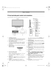
... 10:54 AM Chapter 1: Introduction TV front and side panel controls and connections Model 42XV545U is used in this remote sensor. See "Selecting the TOSHIBA Illumination mode" on the TV's control panel functions as "VIDEO 2" and include standard A/V connections. 6 POWER - When a menu is on-screen, the MENU button on page 41 for updating the television's firmware. page 36). 11 VOLUME C c - High-Definition Multimedia Interface (HDMI 4) input receives digital audio and uncompressed digital video from an HDMI device or uncompressed digital video from a DVI device. XV545U...
... 10:54 AM Chapter 1: Introduction TV front and side panel controls and connections Model 42XV545U is used in this remote sensor. See "Selecting the TOSHIBA Illumination mode" on the TV's control panel functions as "VIDEO 2" and include standard A/V connections. 6 POWER - When a menu is on-screen, the MENU button on page 41 for updating the television's firmware. page 36). 11 VOLUME C c - High-Definition Multimedia Interface (HDMI 4) input receives digital audio and uncompressed digital video from an HDMI device or uncompressed digital video from a DVI device. XV545U...
Owner's Manual - English
Page 11
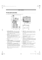
... to receive 1080p signals. 3 PC IN - Two sets of HDMI Licensing LLC. For service use when connecting a personal computer. 4 PC/HDMI 1 (AUDIO) IN - Optical audio output in the Audio Setup menu (- Also see pages 12-19. 1 TV back 2 3 4 Power cord Cable Strap 5 67 8 9 10 1 DIGITAL AUDIO OUT - Note: Standard (composite) video and S-video cables carry only video information; Analog audio outputs for connecting an external Dolby Digital decoder, amplifier, A/V receiver, or home theater system with an optical IR blaster cable (page 12), and then control...
... to receive 1080p signals. 3 PC IN - Two sets of HDMI Licensing LLC. For service use when connecting a personal computer. 4 PC/HDMI 1 (AUDIO) IN - Optical audio output in the Audio Setup menu (- Also see pages 12-19. 1 TV back 2 3 4 Power cord Cable Strap 5 67 8 9 10 1 DIGITAL AUDIO OUT - Note: Standard (composite) video and S-video cables carry only video information; Analog audio outputs for connecting an external Dolby Digital decoder, amplifier, A/V receiver, or home theater system with an optical IR blaster cable (page 12), and then control...
Owner's Manual - English
Page 12
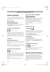
... blaster cable: Visit http://ceaccessories.toshiba.com/ Optical audio cable S-video cable S-video cable is for connecting receivers with an HDMI output. Component video cables (red/green/blue) Optical audio cable is Toshiba's brand of component video.) These cables are for use with video devices with the TV's IR pass-through feature (- page 19). Component video cables come in sets of three and are required for a complete connection. Before purchasing any cables, be purchased from those illustrated herein. Note: An HDMI cable provides the best audio and picture performance...
... blaster cable: Visit http://ceaccessories.toshiba.com/ Optical audio cable S-video cable S-video cable is for connecting receivers with an HDMI output. Component video cables (red/green/blue) Optical audio cable is Toshiba's brand of component video.) These cables are for use with video devices with the TV's IR pass-through feature (- page 19). Component video cables come in sets of three and are required for a complete connection. Before purchasing any cables, be purchased from those illustrated herein. Note: An HDMI cable provides the best audio and picture performance...
Owner's Manual - English
Page 13
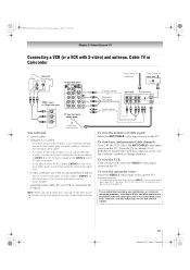
... television programs, videotapes, DVDs, and other materials is set to channel 3 or 4 (whichever channel the Cable box output is prohibited under the Copyright Laws of the VIDEO 2 on the TV right side panel. - Do not connect both types of the standard video cable. - Select the ANT/CABLE video input source on the TV.* Tune the TV to ). For better picture performance, if your camcorder has S-video, connect an S-video cable (plus the audio cables) instead of video cable to change channels. To view the antenna...
... television programs, videotapes, DVDs, and other materials is set to channel 3 or 4 (whichever channel the Cable box output is prohibited under the Copyright Laws of the VIDEO 2 on the TV right side panel. - Do not connect both types of the standard video cable. - Select the ANT/CABLE video input source on the TV.* Tune the TV to ). For better picture performance, if your camcorder has S-video, connect an S-video cable (plus the audio cables) instead of video cable to change channels. To view the antenna...

Owner's Manual - English
Page 19
... back panel • Signal names for computers with a compatible mini D-sub15-pin terminal. • Depending on the DVD's title and the specifications of the PC on the TV are shared with an HDMI terminal, use an HDMI cable (type A connector). If connecting a PC with the HDMI 1 analog audio input terminals (- page 16). "Using the PC settings feature" on the TV, use a PC, set the monitor output resolution on the TV and hear the sound from the TV's speakers...
... back panel • Signal names for computers with a compatible mini D-sub15-pin terminal. • Depending on the DVD's title and the specifications of the PC on the TV are shared with an HDMI terminal, use an HDMI cable (type A connector). If connecting a PC with the HDMI 1 analog audio input terminals (- page 16). "Using the PC settings feature" on the TV, use a PC, set the monitor output resolution on the TV and hear the sound from the TV's speakers...
Owner's Manual - English
Page 22
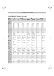
... Chapter 3: Using the remote control Remote Control functional key chart REMOTE CONTROL KEY SLEEP MODE SELECT POWER 1 2 3 4 5 6 7 8 9 0 100/-/+10 INPUT B b C3 #c ENTER FAV BROWSER /SETUP MENU THINC/ TOP MENU GUIDE PAGE +/- Pause Play Stop 22 XV545U (E/F) Web 177.8:228.6 Menu THINC Guide ---Volume up/ down*1 Channel up /down ---Mute*1 ----(TV) Display ----- Menu Cable menu Action, menu THINC THINC THINC Guide Page up/ down Volume up/ down*1 Channel up/ down Exit Mute*1 Guide Info (TV) Display Last Channel Cable Guide Cable page up/down Volume up/ down*1 Channel up...
... Chapter 3: Using the remote control Remote Control functional key chart REMOTE CONTROL KEY SLEEP MODE SELECT POWER 1 2 3 4 5 6 7 8 9 0 100/-/+10 INPUT B b C3 #c ENTER FAV BROWSER /SETUP MENU THINC/ TOP MENU GUIDE PAGE +/- Pause Play Stop 22 XV545U (E/F) Web 177.8:228.6 Menu THINC Guide ---Volume up/ down*1 Channel up /down ---Mute*1 ----(TV) Display ----- Menu Cable menu Action, menu THINC THINC THINC Guide Page up/ down Volume up/ down*1 Channel up/ down Exit Mute*1 Guide Info (TV) Display Last Channel Cable Guide Cable page up/down Volume up/ down*1 Channel up...
Owner's Manual - English
Page 33
... LINK Player Control Start Demo Mode Picture Settings Noise Reduction Auto Brightness Sensor ColorMaster x.v.Color Selection Game Mode Theater Settings TheaterLock Digital Audio Selector Audio Settings Advanced Audio Settings Audio Setup CC Selector Base CC Mode Digital CC Settings Auto Input Input Labeling Channel Labeling Menu Language Channel Browser Setup Enable Rating Blocking Edit Rating Limits Channels Block Input Lock Control Panel Lock GameTimer® New PIN Code Installation REGZA LINK Setup Sleep Timer HDMI Settings PC Settings TOSHIBA Illumination Power-On Mode Demo Mode Energy...
... LINK Player Control Start Demo Mode Picture Settings Noise Reduction Auto Brightness Sensor ColorMaster x.v.Color Selection Game Mode Theater Settings TheaterLock Digital Audio Selector Audio Settings Advanced Audio Settings Audio Setup CC Selector Base CC Mode Digital CC Settings Auto Input Input Labeling Channel Labeling Menu Language Channel Browser Setup Enable Rating Blocking Edit Rating Limits Channels Block Input Lock Control Panel Lock GameTimer® New PIN Code Installation REGZA LINK Setup Sleep Timer HDMI Settings PC Settings TOSHIBA Illumination Power-On Mode Demo Mode Energy...
Owner's Manual - English
Page 36
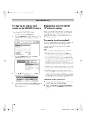
... the remote control or TV control panel, your TV will stop only on the remote control. • Programming channels when the ANT/CABLE input is configured for Cable will take substantially longer than when the antenna input is set to Antenna, the automatic channel programming process adds newly found channels to the existing set to program channels into the TV's channel memory. Follow the steps below .) Setup Installation REGZA LINK Setup Sleep Timer HDMI Settings PC Settings TOSHIBA Illumination Power-On Mode Demo Mode Energy Saving Mode On Power-Saving...
... the remote control or TV control panel, your TV will stop only on the remote control. • Programming channels when the ANT/CABLE input is configured for Cable will take substantially longer than when the antenna input is set to Antenna, the automatic channel programming process adds newly found channels to the existing set to program channels into the TV's channel memory. Follow the steps below .) Setup Installation REGZA LINK Setup Sleep Timer HDMI Settings PC Settings TOSHIBA Illumination Power-On Mode Demo Mode Energy Saving Mode On Power-Saving...
Owner's Manual - English
Page 61
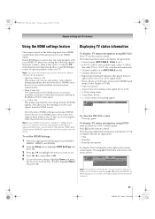
... Chapter 6: Using the TV's features Using the HDMI settings feature This menu consists of the following additional information will display for off air digital channels (if applicable): • Title • Duration • Detailed description To display Next information, press Q on the remote control again. To set the HDMI Settings: 1 Select the appropriate HDMI input mode (HDMI 1, HDMI 2, HDMI 3, or HDMI 4). 2 From the Setup menu, highlight HDMI Settings and press T. 3 Press B or b to the factory defaults, highlight Reset and press...
... Chapter 6: Using the TV's features Using the HDMI settings feature This menu consists of the following additional information will display for off air digital channels (if applicable): • Title • Duration • Detailed description To display Next information, press Q on the remote control again. To set the HDMI Settings: 1 Select the appropriate HDMI input mode (HDMI 1, HDMI 2, HDMI 3, or HDMI 4). 2 From the Setup menu, highlight HDMI Settings and press T. 3 Press B or b to the factory defaults, highlight Reset and press...
Owner's Manual - English
Page 69
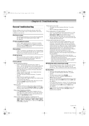
... broadcast difficulties. Sound problems • Check the antenna/cable connections (- Chapter 2). • The station may help synchronize the sound to an external A/V device (e.g., DVD player, video game system, set (- Black box on the TV control panel for the program you are watching an analog channel (off-air broadcast or Cable TV), you are out of this issue. page 66). Try another channel. • Adjust the picture qualities (- Poor color or no sound, try the control panel buttons. If you connect an S-video cable, be muted...
... broadcast difficulties. Sound problems • Check the antenna/cable connections (- Chapter 2). • The station may help synchronize the sound to an external A/V device (e.g., DVD player, video game system, set (- Black box on the TV control panel for the program you are watching an analog channel (off-air broadcast or Cable TV), you are out of this issue. page 66). Try another channel. • Adjust the picture qualities (- Poor color or no sound, try the control panel buttons. If you connect an S-video cable, be muted...
Owner's Manual - English
Page 74
... for a period of antenna systems are your needs and help us to change, modify, or extend the terms of these warranties in any state of purchase to original consumers in the United States. Failure to the rental firm, whichever comes first. or Puerto Rico. (4) Labor service charges for set installation, setup, adjustment of customer controls, and installation or repair of ninety (90) days...
... for a period of antenna systems are your needs and help us to change, modify, or extend the terms of these warranties in any state of purchase to original consumers in the United States. Failure to the rental firm, whichever comes first. or Puerto Rico. (4) Labor service charges for set installation, setup, adjustment of customer controls, and installation or repair of ninety (90) days...
Owner's Manual - English
Page 75
... set installation, setup, adjustment of customer controls, and installation or repair of God, alteration, power failures, power surges or power shortages, lightning, other electrical faults, or repairs, modifications or replacements by their own warranty); h. Reception problems caused by inadequate antenna systems are used for a period of one (1) year after the date of shipment to material defects in your home when warranty service is required. c. Depending on which the TOSHIBA...
... set installation, setup, adjustment of customer controls, and installation or repair of God, alteration, power failures, power surges or power shortages, lightning, other electrical faults, or repairs, modifications or replacements by their own warranty); h. Reception problems caused by inadequate antenna systems are used for a period of one (1) year after the date of shipment to material defects in your home when warranty service is required. c. Depending on which the TOSHIBA...
Owner's Manual - English
Page 78
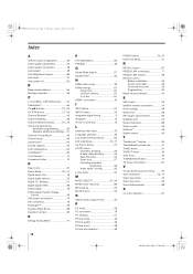
... 56 Video inputs, locking 56 Locks menu 54 M MODE SELECT 21, 24 MPEG noise reduction 66 MTS feature 52 MUTE button 52 O Optical audio output format 53 P PC Audio 58 PC connection 19 PC settings 57 Picture mode 49 Picture quality 49 Picture scroll 48 Picture size selection 46 POWER button 10, 21 Power-On Mode 41 R RECALL button 61 REGZA LINK connection 17 REGZA LINK feature 59 Remote control Battery installation 20 Device code table 26 Functional key chart 22 Programming 24 Reset Factory Defaults...
... 56 Video inputs, locking 56 Locks menu 54 M MODE SELECT 21, 24 MPEG noise reduction 66 MTS feature 52 MUTE button 52 O Optical audio output format 53 P PC Audio 58 PC connection 19 PC settings 57 Picture mode 49 Picture quality 49 Picture scroll 48 Picture size selection 46 POWER button 10, 21 Power-On Mode 41 R RECALL button 61 REGZA LINK connection 17 REGZA LINK feature 59 Remote control Battery installation 20 Device code table 26 Functional key chart 22 Programming 24 Reset Factory Defaults...
Printable Spec Sheet
Page 2
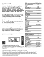
... Inputs ColorStream® Component Video Inputs Front A/V / Rear A/V / Rear S-Video High Res PC Input: S-XGA, 15 pin, D-sub terminal IR Pass-Through Analog Audio Out Dolby® Digital Optical Out 4 (1 Side) 2 1 / 1 /1 1 • Fixed • REMOTE CONTROL: Type 4 Item Universal4 PRODUCT & PACKAGING: VESA® Mounting Pattern5 200 x 400 mm Unit Dimensions (with a High-Gloss Black Cabinet Screen Size (measured diagonally) 42.0" LCD PANEL: Resolution Dynamic Backlight Control 10 Bit LCD Panel Backlight Color Depth 1080p DynaLightTM • ColorBurstTM WCG VIDEO: Digital Video...
... Inputs ColorStream® Component Video Inputs Front A/V / Rear A/V / Rear S-Video High Res PC Input: S-XGA, 15 pin, D-sub terminal IR Pass-Through Analog Audio Out Dolby® Digital Optical Out 4 (1 Side) 2 1 / 1 /1 1 • Fixed • REMOTE CONTROL: Type 4 Item Universal4 PRODUCT & PACKAGING: VESA® Mounting Pattern5 200 x 400 mm Unit Dimensions (with a High-Gloss Black Cabinet Screen Size (measured diagonally) 42.0" LCD PANEL: Resolution Dynamic Backlight Control 10 Bit LCD Panel Backlight Color Depth 1080p DynaLightTM • ColorBurstTM WCG VIDEO: Digital Video...


