Owner's Manual - English
Page 3
.... 2) Keep these recommendations and precautions and heed all warnings when installing your doctor. • ALWAYS contact a service technician to inspect the TV any time it has been damaged or dropped. 15) CAUTION: • To reduce the risk of electric shock, do not use a ... the floor or a sturdy, level, stable surface that produce heat. 9) Do not defeat the safety purpose of the TV pedestal to the floor. The LCD panel inside the TV contains glass and a toxic liquid. Installation, Care, and Service Installation Follow these instructions. 3) Heed all warnings. 4) Follow all ...
.... 2) Keep these recommendations and precautions and heed all warnings when installing your doctor. • ALWAYS contact a service technician to inspect the TV any time it has been damaged or dropped. 15) CAUTION: • To reduce the risk of electric shock, do not use a ... the floor or a sturdy, level, stable surface that produce heat. 9) Do not defeat the safety purpose of the TV pedestal to the floor. The LCD panel inside the TV contains glass and a toxic liquid. Installation, Care, and Service Installation Follow these instructions. 3) Heed all warnings. 4) Follow all ...

Owner's Manual - English
Page 4
... the end of its useful life, dispose of the used TV by ultraviolet radiation from the TV if you need to clean the LCD screen, follow this WARNING may expose you are in this manual to a Toshiba Authorized Service Center. 38) If you use only replacement parts specified by the manufacturer. ...power cord and disconnect the antenna from the sun. Opening and removing the covers may result in the LCD panel contains a small amount of mercury. Disposal may be regulated due to use the TV in a room whose temperature is in safe operating condition. 39) The cold cathode fluorescent lamp in...
... the end of its useful life, dispose of the used TV by ultraviolet radiation from the TV if you need to clean the LCD screen, follow this WARNING may expose you are in this manual to a Toshiba Authorized Service Center. 38) If you use only replacement parts specified by the manufacturer. ...power cord and disconnect the antenna from the sun. Opening and removing the covers may result in the LCD panel contains a small amount of mercury. Disposal may be regulated due to use the TV in a room whose temperature is in safe operating condition. 39) The cold cathode fluorescent lamp in...
Owner's Manual - English
Page 5
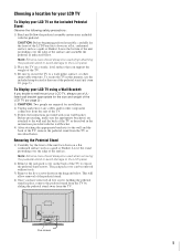
... be used when removing the pedestal stand to avoid damage to the LCD panel. 2) Remove the jack pack cover on a flat, cushioned surface such as indicated below . Five screws 5 Choosing a location for your LCD TV To Display your LCD TV on the included Pedestal Stand: Observe the following safety precautions: 1)... carefully lay the front of the LCD Panel face down on the back of the TV to wall mount your LCD TV, always use the included strap located at the rear of the TV as described below . item 20, page 3). This will allow removal of the LCD TV (- Before proceeding, make sure the...
... be used when removing the pedestal stand to avoid damage to the LCD panel. 2) Remove the jack pack cover on a flat, cushioned surface such as indicated below . Five screws 5 Choosing a location for your LCD TV To Display your LCD TV on the included Pedestal Stand: Observe the following safety precautions: 1)... carefully lay the front of the LCD Panel face down on the back of the TV to wall mount your LCD TV, always use the included strap located at the rear of the TV as described below . item 20, page 3). This will allow removal of the LCD TV (- Before proceeding, make sure the...
Owner's Manual - English
Page 6
...circuit different from that interference will disappear in a short period of time. 2) The LCD panel contained in accordance with this TV is incorporated under license from Dolby Laboratories. moving image is no guarantee that to which...LCD technology, is not a sign of malfunction, and is : Toshiba America Consumer Products, L.L.C. 82 Totowa Rd. however, there may cause harmful interference to radio communications. WOW technology is manufactured using an extremely high level of precision technology; FCC Declaration of Conformity Compliance Statement (Part 15): The Toshiba 42HL167...
...circuit different from that interference will disappear in a short period of time. 2) The LCD panel contained in accordance with this TV is incorporated under license from Dolby Laboratories. moving image is no guarantee that to which...LCD technology, is not a sign of malfunction, and is : Toshiba America Consumer Products, L.L.C. 82 Totowa Rd. however, there may cause harmful interference to radio communications. WOW technology is manufactured using an extremely high level of precision technology; FCC Declaration of Conformity Compliance Statement (Part 15): The Toshiba 42HL167...

Owner's Manual - English
Page 7
... Service 3 Chapter 1: Introduction 9 Welcome to Toshiba 9 Features of your new TV 9 Overview of steps for installing, setting up, and using your new TV 10 TV front and side panel controls and connections 11 TV back panel connections 12 Chapter 2: Connecting your TV 13 Overview of cable types 13 About the ...the ANT terminal 39 Programming channels into the TV's channel memory . . . . 40 Programming channels automatically 40 Manually adding and deleting channels in the channel memory 40 Setting the Auto Input feature 41 Labeling channels 42 Setting the HDMI™ audio mode 43 ...
... Service 3 Chapter 1: Introduction 9 Welcome to Toshiba 9 Features of your new TV 9 Overview of steps for installing, setting up, and using your new TV 10 TV front and side panel controls and connections 11 TV back panel connections 12 Chapter 2: Connecting your TV 13 Overview of cable types 13 About the ...the ANT terminal 39 Programming channels into the TV's channel memory . . . . 40 Programming channels automatically 40 Manually adding and deleting channels in the channel memory 40 Setting the Auto Input feature 41 Labeling channels 42 Setting the HDMI™ audio mode 43 ...
Owner's Manual - English
Page 8
Chapter 7: Using the TV's advanced features 67 Using the advanced picture settings features 67 Using dynamic contrast 67 Using the static gamma feature 67 Selecting the color temperature 68 ... WOW™ surround sound feature 71 Chapter 8: Troubleshooting 72 General troubleshooting 72 LED indications 74 Chapter 9: Appendix 75 Specifications 75 Limited United States Warranty for LCD Televisions 26" and Larger 76 Limited Canadian Warranty for Toshiba Brand Flat Panel Televisions 77 Index 80 8
Chapter 7: Using the TV's advanced features 67 Using the advanced picture settings features 67 Using dynamic contrast 67 Using the static gamma feature 67 Selecting the color temperature 68 ... WOW™ surround sound feature 71 Chapter 8: Troubleshooting 72 General troubleshooting 72 LED indications 74 Chapter 9: Appendix 75 Specifications 75 Limited United States Warranty for LCD Televisions 26" and Larger 76 Limited Canadian Warranty for Toshiba Brand Flat Panel Televisions 77 Index 80 8
Owner's Manual - English
Page 10
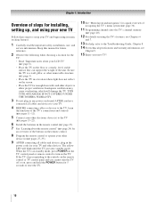
...AFTER you cannot turn on the remote control or TV control panel and you have connected all cables and devices, plug in any power cords until the TV goes into the TV's channel memory (- THIS TYPE OF DAMAGE IS NOT COVERED UNDER THE TOSHIBA WARRANTY. 3 Do not plug in the power...this manual for future reference. 2 Observe the following when choosing a location for the TV: • Read "Important notes about the remote control" (- When the TV is in the remote control (- pages 11-12). 5 Connect your LCD TV" (- page 36). 11 Programming channels into standby mode. page 40). 12 For ...
...AFTER you cannot turn on the remote control or TV control panel and you have connected all cables and devices, plug in any power cords until the TV goes into the TV's channel memory (- THIS TYPE OF DAMAGE IS NOT COVERED UNDER THE TOSHIBA WARRANTY. 3 Do not plug in the power...this manual for future reference. 2 Observe the following when choosing a location for the TV: • Read "Important notes about the remote control" (- When the TV is in the remote control (- pages 11-12). 5 Connect your LCD TV" (- page 36). 11 Programming channels into standby mode. page 40). 12 For ...
Owner's Manual - English
Page 11
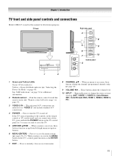
... buttons function as up/down/left/right menu navigation buttons. 6 MENU (ENTER) - When no menu is on the remote control or TV control panel and you are referred to instantly close an on page 23). 3 VIDEO-2 IN - Press to as the ENTER button. 7 EXIT ... "LED indications" on the TV control panel for additional information. 2 Remote sensor - If the TV stops responding to reset the TV. 5 ARROWS BbC c - Press to turn off . Press to access the menu system (- Chapter 1: Introduction TV front and side panel controls and connections Model 42HL167 is used in this remote ...
... buttons function as up/down/left/right menu navigation buttons. 6 MENU (ENTER) - When no menu is on the remote control or TV control panel and you are referred to instantly close an on page 23). 3 VIDEO-2 IN - Press to as the ENTER button. 7 EXIT ... "LED indications" on the TV control panel for additional information. 2 Remote sensor - If the TV stops responding to reset the TV. 5 ARROWS BbC c - Press to turn off . Press to access the menu system (- Chapter 1: Introduction TV front and side panel controls and connections Model 42HL167 is used in this remote ...

Owner's Manual - English
Page 12
... Component video cables carry only video information; separate audio cables are required for connecting devices with component video output, such as a Toshiba DVD player with ColorStream®. For service use when connecting a personal computer. 7 8 9 10 7 ANT - Manufactured under ...and High-Definition Multimedia Interface are required for connecting devices with composite video or S-video output. Chapter 1: Introduction TV back panel connections For an explanation of ColorStream® high-definition component video inputs (with standard stereo audio inputs) for a complete ...
... Component video cables carry only video information; separate audio cables are required for connecting devices with component video output, such as a Toshiba DVD player with ColorStream®. For service use when connecting a personal computer. 7 8 9 10 7 ANT - Manufactured under ...and High-Definition Multimedia Interface are required for connecting devices with composite video or S-video output. Chapter 1: Introduction TV back panel connections For an explanation of ColorStream® high-definition component video inputs (with standard stereo audio inputs) for a complete ...
Owner's Manual - English
Page 14
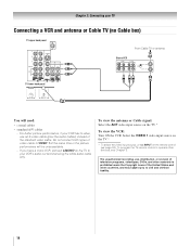
... cables • standard A/V cables - For better picture performance, if your TV Connecting a VCR and antenna or Cable TV (no Cable box) TV upper back panel From Cable TV or antenna Stereo VCR VIDEO AUDIO L R IN CH 3 CH 4 OUT L R IN from ANT OUT to TV TV lower back panel You will be unacceptable. - To view the antenna or Cable...
... cables • standard A/V cables - For better picture performance, if your TV Connecting a VCR and antenna or Cable TV (no Cable box) TV upper back panel From Cable TV or antenna Stereo VCR VIDEO AUDIO L R IN CH 3 CH 4 OUT L R IN from ANT OUT to TV TV lower back panel You will be unacceptable. - To view the antenna or Cable...
Owner's Manual - English
Page 15
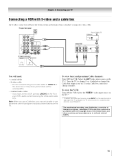
... white audio cable only. Note: When you have a mono VCR, connect L/MONO on the TV to program or access certain features on the remote control (- TV upper back panel From Cable TV Cable box IN CH 3 CH 4 OUT TV lower back panel stereo VCR VIDEO AUDIO L R IN CH 3 CH 4 OUT L R IN from ANT OUT to operate...
... white audio cable only. Note: When you have a mono VCR, connect L/MONO on the TV to program or access certain features on the remote control (- TV upper back panel From Cable TV Cable box IN CH 3 CH 4 OUT TV lower back panel stereo VCR VIDEO AUDIO L R IN CH 3 CH 4 OUT L R IN from ANT OUT to operate...
Owner's Manual - English
Page 16
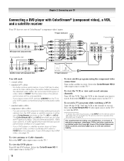
... on the remote control (- Select the ColorStream HD-1 video input source on the TV* to your VCR has S-video, use , distribution, or revision of ColorStream® (component video) inputs. TV upper back panel From antenna Y PB PR COMPONENT VIDEO S-VIDEO VIDEO OUT OUT DVD player with ...the VIDEO 1 video input source on the satellite receiver. You can be used with component video TV lower back panel You will be unacceptable. - Select the ColorStream HD-1 video input source on the TV.* To view satellite programs using the white audio cable only. • standard audio cables &#...
... on the remote control (- Select the ColorStream HD-1 video input source on the TV* to your VCR has S-video, use , distribution, or revision of ColorStream® (component video) inputs. TV upper back panel From antenna Y PB PR COMPONENT VIDEO S-VIDEO VIDEO OUT OUT DVD player with ...the VIDEO 1 video input source on the satellite receiver. You can be used with component video TV lower back panel You will be unacceptable. - Select the ColorStream HD-1 video input source on the TV.* To view satellite programs using the white audio cable only. • standard audio cables &#...
Owner's Manual - English
Page 17
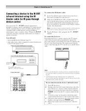
page 13) • other audio/video cables as Toshiba infrared remotecontrolled VCRs or DVD players) enclosed within an entertainment center or similar cabinet. The signal passes from device) TV upper back panel Note: • If you use the TV's IR OUT terminal (infrared passthrough) to remotely operate (through ... the front of IR-controlled DVD player (for the desired function. To control the device(s): Point either the device's remote control or the TV remote control (that you do not have a second device, attach the second wand in a similar manner. (See illustration.) Note: If ...
page 13) • other audio/video cables as Toshiba infrared remotecontrolled VCRs or DVD players) enclosed within an entertainment center or similar cabinet. The signal passes from device) TV upper back panel Note: • If you use the TV's IR OUT terminal (infrared passthrough) to remotely operate (through ... the front of IR-controlled DVD player (for the desired function. To control the device(s): Point either the device's remote control or the TV remote control (that you do not have a second device, attach the second wand in a similar manner. (See illustration.) Note: If ...
Owner's Manual - English
Page 18
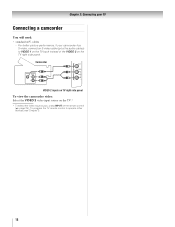
... control (- Camcorder VIDEO AUDIO OUT L R VIDEO 2 inputs on TV right side panel To view the camcorder video: Select the VIDEO 2 video input source on the TV.* * To select the video input source, press INPUT on the TV right side panel. For better picture performance, if your TV Connecting a camcorder You will need: • standard A/V cables - page...
... control (- Camcorder VIDEO AUDIO OUT L R VIDEO 2 inputs on TV right side panel To view the camcorder video: Select the VIDEO 2 video input source on the TV.* * To select the video input source, press INPUT on the TV right side panel. For better picture performance, if your TV Connecting a camcorder You will need: • standard A/V cables - page...
Owner's Manual - English
Page 19
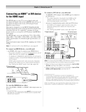
... a PC to operate other devices, see Chapter 3. [1] EIA/CEA-861-D compliance covers the transmission of uncompressed digital video with the TV. page 43). TV upper back panel TV lower back panel DVI device VIDEO AUDIO L R IN IN DVI / HDCP OUT OUT L R Note: To ensure that the HDMI or DVI device... transfers video only. For proper operation, it is 6.6 ft (2m). • one HDMI cable (type A connector) per DVI device - TV lower back panel To connect a DVI device, you use an HDMI cable with HDMI or DVI output). Separate analog audio cables are required (see page 75. ...
... a PC to operate other devices, see Chapter 3. [1] EIA/CEA-861-D compliance covers the transmission of uncompressed digital video with the TV. page 43). TV upper back panel TV lower back panel DVI device VIDEO AUDIO L R IN IN DVI / HDCP OUT OUT L R Note: To ensure that the HDMI or DVI device... transfers video only. For proper operation, it is 6.6 ft (2m). • one HDMI cable (type A connector) per DVI device - TV lower back panel To connect a DVI device, you use an HDMI cable with HDMI or DVI output). Separate analog audio cables are required (see page 75. ...
Owner's Manual - English
Page 20
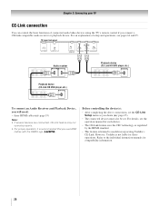
...Toshiba's CE-Link. Chapter 2: Connecting your TV CE-Link connection You can control the basic functions of setup and operations, see the operation manual for each device. • The CE-Link feature uses the CEC technology as you will need: • three HDMI cables (- However, Toshiba...limited to the individual instruction manuals for those operations. Before controlling the device(s): • After completing the above connections, set . TV lower back panel VIDEO AUDIO L R IN OUT L R Audio receiver HDMI IN HDMI OUT Playback device (CE-Link HD DVD player,etc.) ...
...Toshiba's CE-Link. Chapter 2: Connecting your TV CE-Link connection You can control the basic functions of setup and operations, see the operation manual for each device. • The CE-Link feature uses the CEC technology as you will need: • three HDMI cables (- However, Toshiba...limited to the individual instruction manuals for those operations. Before controlling the device(s): • After completing the above connections, set . TV lower back panel VIDEO AUDIO L R IN OUT L R Audio receiver HDMI IN HDMI OUT Playback device (CE-Link HD DVD player,etc.) ...
Owner's Manual - English
Page 21
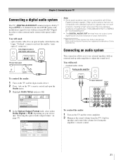
... control. 21 Dolby, and the double-D symbol are not compatible with standard optical out signals may damage speakers or headphones. LINE IN LR TV upper back panel Audio Digital Audio Selector Audio Settings Advanced Audio Settings Audio Setup 4 In the Optical Output Format field, select either Dolby Digital or PCM, ... connection allows you to use with an external Dolby® Digital decoder or other digital audio system LINE IN LR Optical Audio IN TV lower back panel Note: • Some audio systems may not output some digital audio sources because of Dolby Laboratories.
... control. 21 Dolby, and the double-D symbol are not compatible with standard optical out signals may damage speakers or headphones. LINE IN LR TV upper back panel Audio Digital Audio Selector Audio Settings Advanced Audio Settings Audio Setup 4 In the Optical Output Format field, select either Dolby Digital or PCM, ... connection allows you to use with an external Dolby® Digital decoder or other digital audio system LINE IN LR Optical Audio IN TV lower back panel Note: • Some audio systems may not output some digital audio sources because of Dolby Laboratories.

Owner's Manual - English
Page 22
...800 × 600 60Hz XGA 1024 × 768 60Hz Other formats or non-standard signals will not be displayed: Format Resolution V. TV upper back panel TV lower back panel PC audio output Conversion adapter (if necessary) • To use an analog RGB (15-pin) computer cable and a PC audio ...cable. Signal name Pin No. TV upper back panel TV lower back panel Computer PC audio cable • An adapter is not needed for mini D-sub 15-pin connector Pin No. For detailed signal specifications...
...800 × 600 60Hz XGA 1024 × 768 60Hz Other formats or non-standard signals will not be displayed: Format Resolution V. TV upper back panel TV lower back panel PC audio output Conversion adapter (if necessary) • To use an analog RGB (15-pin) computer cable and a PC audio ...cable. Signal name Pin No. TV upper back panel TV lower back panel Computer PC audio cable • An adapter is not needed for mini D-sub 15-pin connector Pin No. For detailed signal specifications...
Owner's Manual - English
Page 36
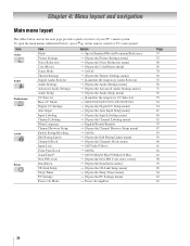
To open the main menus (illustrated below and on the remote control or TV control panel. Icon Video Audio Preferences Locks Setup Item Mode Picture Settings Noise Reduction ...Input Labeling Channel Labeling Menu Language Channel Browser Setup Enable Rating Blocking Edit Rating Limits Channels Block Input Lock Front Panel Lock GameTimer® New PIN Code Installation CE-Link Setup Sleep Timer PC Settings Power-On Mode Option S ...] S Power-Saving/Fast Page 53 53 68 69 70 50 55 56 71 56 55 54 54 41 46 42 39 47 59 59 60 61 62 62 58 39 65 64 63 45 36 Chapter 4: Menu layout and navigation...
To open the main menus (illustrated below and on the remote control or TV control panel. Icon Video Audio Preferences Locks Setup Item Mode Picture Settings Noise Reduction ...Input Labeling Channel Labeling Menu Language Channel Browser Setup Enable Rating Blocking Edit Rating Limits Channels Block Input Lock Front Panel Lock GameTimer® New PIN Code Installation CE-Link Setup Sleep Timer PC Settings Power-On Mode Option S ...] S Power-Saving/Fast Page 53 53 68 69 70 50 55 56 71 56 55 54 54 41 46 42 39 47 59 59 60 61 62 62 58 39 65 64 63 45 36 Chapter 4: Menu layout and navigation...
Owner's Manual - English
Page 37
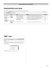
To open the Installation menu (illustrated below), press Y on the remote control or TV control panel, open the Installation sub-menu. Press Y, open the Setup menu, and then open the Setup menu, select Installation, and press T. Icon Terrestrial ... the Input Configuration menu] S [Start] S [Scans for new channels on the remote control. THINC Applications CE-Link Player Control Channel Browser Favorites Browser * Toshiba Home Interactive Network Connection. 37 The THINC menu is not part of the main menu system. Chapter 4: Menu layout and navigation Setup/Installation menu layout...
To open the Installation menu (illustrated below), press Y on the remote control or TV control panel, open the Installation sub-menu. Press Y, open the Setup menu, and then open the Setup menu, select Installation, and press T. Icon Terrestrial ... the Input Configuration menu] S [Start] S [Scans for new channels on the remote control. THINC Applications CE-Link Player Control Channel Browser Favorites Browser * Toshiba Home Interactive Network Connection. 37 The THINC menu is not part of the main menu system. Chapter 4: Menu layout and navigation Setup/Installation menu layout...

