Operating Instructions
Page 5
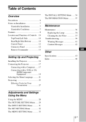
...Rear/Right Side/Bottom 10 Control Panel 12 Connector Panel 12 Remote Commander 13 Setting Up and Projecting Installing the Projector 16 Connecting the Projector 17 Connecting with a Computer ......17 Connecting with a VCR or 15k RGB/Component Equipment 19 Selecting the Menu ...Language ..........21 Projecting 23 Effective Tools for Your Presentation 27 The INSTALL SETTING Menu ..... 34 The INFORMATION Menu 35 Maintenance Maintenance 36 Replacing the Lamp...
...Rear/Right Side/Bottom 10 Control Panel 12 Connector Panel 12 Remote Commander 13 Setting Up and Projecting Installing the Projector 16 Connecting the Projector 17 Connecting with a Computer ......17 Connecting with a VCR or 15k RGB/Component Equipment 19 Selecting the Menu ...Language ..........21 Projecting 23 Effective Tools for Your Presentation 27 The INSTALL SETTING Menu ..... 34 The INFORMATION Menu 35 Maintenance Maintenance 36 Replacing the Lamp...

Operating Instructions
Page 6
... place anything near these will damage the cabinet. • Avoid touching the lens. On LCD data projector • The LCD data projector is completed. • Do not spread a cloth or paper under the unit. Use a cover over fluorescent lamps to the projector. You may occur, causing picture degradation or damage to avoid lowering the contrast ratio...
... place anything near these will damage the cabinet. • Avoid touching the lens. On LCD data projector • The LCD data projector is completed. • Do not spread a cloth or paper under the unit. Use a cover over fluorescent lamps to the projector. You may occur, causing picture degradation or damage to avoid lowering the contrast ratio...

Operating Instructions
Page 7
These installations may rise rapidly. Poorly ventilated • Allow adequate air circulation to the projector. Lamp off automatically after one minute. • Leave space of paper. Tilting the unit out of the range of the adjuster setting Avoid using...block the ventilation holes. Very dusty Avoid installing the unit in the following conditions. Highly heated and humid Unsuitable Conditions Do not use the projector under the following situations. Toppling the unit Avoid using when the unit is a lot of the adjuster setting. It may cause malfunction. ...
These installations may rise rapidly. Poorly ventilated • Allow adequate air circulation to the projector. Lamp off automatically after one minute. • Leave space of paper. Tilting the unit out of the range of the adjuster setting Avoid using...block the ventilation holes. Very dusty Avoid installing the unit in the following conditions. Highly heated and humid Unsuitable Conditions Do not use the projector under the following situations. Toppling the unit Avoid using when the unit is a lot of the adjuster setting. It may cause malfunction. ...

Operating Instructions
Page 8
...Sony's unique new, highefficiency optical system allows the 165 W UHP lamp a light output of 2000 ANSI lumen (VPL-CX5) or 1800 ANSI lumen (VPL-CS5). ... 1) The SXGA and SXGA+ signals are allocated on the image, the FREEZE key for keeping the image projected even if the equipment is preset for 25 kinds of the projector... key, and the projector automatically performs the setups required before use the supplied Remote Commander as VGA, SVGA, XGA, SXGA1) and SXGA+1) signals, which all can make the presentation easily without connecting the computer. The projector opens the lens protector...
...Sony's unique new, highefficiency optical system allows the 165 W UHP lamp a light output of 2000 ANSI lumen (VPL-CX5) or 1800 ANSI lumen (VPL-CS5). ... 1) The SXGA and SXGA+ signals are allocated on the image, the FREEZE key for keeping the image projected even if the equipment is preset for 25 kinds of the projector... key, and the projector automatically performs the setups required before use the supplied Remote Commander as VGA, SVGA, XGA, SXGA1) and SXGA+1) signals, which all can make the presentation easily without connecting the computer. The projector opens the lens protector...

Operating Instructions
Page 10
... the projector is in green when the power is turned on. - Once in standby mode, you press the key, the input signal switches as follows: INPUT A t MS t VIDEO t S VIDEO (VPL-CX5 only) 10 GB Location and Function of Controls Top/Front/Left Side 1 TILT 2 3 4 5 7 6 8 Rear/Right Side/...Bottom qd qf 9 0 qg qa qh qs qj t 1 I / 1 (on/standby) key Turns on page 11. 4 INPUT key Selects the input signal. For details on the LAMP/COVER and the TEMP...
... the projector is in green when the power is turned on. - Once in standby mode, you press the key, the input signal switches as follows: INPUT A t MS t VIDEO t S VIDEO (VPL-CX5 only) 10 GB Location and Function of Controls Top/Front/Left Side 1 TILT 2 3 4 5 7 6 8 Rear/Right Side/...Bottom qd qf 9 0 qg qa qh qs qj t 1 I / 1 (on/standby) key Turns on page 11. 4 INPUT key Selects the input signal. For details on the LAMP/COVER and the TEMP...

Operating Instructions
Page 11
...) 8 Connector/Control panel For details, see "Cleaning the Air Filter" on page 12. 9 Rear remote control detector 0 Ventilation holes (intake) qa Lamp cover qs Powered tilt adjuster qd Speaker qf Security lock Connects to an optional security cable (Kensington's). qj Ventilation holes (intake)/air filter cover Notes... Tilt menu and adjust the tilt using the M/ m/ How to use the powered tilt adjuster To adjust the height Adjust the height of the projector as it may cause internal heat build-up. • Do not place your hand or objects near the ventilation holes as follows: 1 Press ...
...) 8 Connector/Control panel For details, see "Cleaning the Air Filter" on page 12. 9 Rear remote control detector 0 Ventilation holes (intake) qa Lamp cover qs Powered tilt adjuster qd Speaker qf Security lock Connects to an optional security cable (Kensington's). qj Ventilation holes (intake)/air filter cover Notes... Tilt menu and adjust the tilt using the M/ m/ How to use the powered tilt adjuster To adjust the height Adjust the height of the projector as it may cause internal heat build-up. • Do not place your hand or objects near the ventilation holes as follows: 1 Press ...

Operating Instructions
Page 12
...A POWER SAVING MENU VIDEO S VIDEO TEMP/FAN PUSH ENTER LAMP/COVER ACCESS AUDIO INPUT A 1 POWER SAVING MENU 2 PUSH ENTER VIDEO S VIDEO TEMP/FAN 3 LAMP/COVER 4 56 1 POWER SAVING indicator Lights up when the projector is not secured firmly. When "Power Saving" in the menu... its life or becomes a high temperature. - Lights up when temperature inside the projector becomes unusually high. - Connector Panel 1 2 3 4 5 ACCESS AUDIO 6 7 INPUT A POWER SAVING MENU VIDEO S VIDEO TEMP/FAN PUSH ENTER LAMP/COVER 1 INPUT A connector (HD D-sub 15-pin, female) Connect to the...
...A POWER SAVING MENU VIDEO S VIDEO TEMP/FAN PUSH ENTER LAMP/COVER ACCESS AUDIO INPUT A 1 POWER SAVING MENU 2 PUSH ENTER VIDEO S VIDEO TEMP/FAN 3 LAMP/COVER 4 56 1 POWER SAVING indicator Lights up when the projector is not secured firmly. When "Power Saving" in the menu... its life or becomes a high temperature. - Lights up when temperature inside the projector becomes unusually high. - Connector Panel 1 2 3 4 5 ACCESS AUDIO 6 7 INPUT A POWER SAVING MENU VIDEO S VIDEO TEMP/FAN PUSH ENTER LAMP/COVER 1 INPUT A connector (HD D-sub 15-pin, female) Connect to the...
Operating Instructions
Page 13
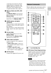
...(Auto Pixel Alignment) key Adjusts a picture clearest automatically while a signal is lit. 6 Video input connector Connect to this connector. 3 Memory Stick slot (VPL-CX5 only) The Memory Stick can be inserted. Notes • Press the APA key when the full image is set to "Off." For details, see...Never insert an object other than the Memory Stick. Do not remove the Memory Stick while the access lamp is input from the computer, connect to the audio output of the VCR. 5 Access lamp Lights during having access to the S video output (Y/C video output) of Controls GB Used when "...
...(Auto Pixel Alignment) key Adjusts a picture clearest automatically while a signal is lit. 6 Video input connector Connect to this connector. 3 Memory Stick slot (VPL-CX5 only) The Memory Stick can be inserted. Notes • Press the APA key when the full image is set to "Off." For details, see...Never insert an object other than the Memory Stick. Do not remove the Memory Stick while the access lamp is input from the computer, connect to the audio output of the VCR. 5 Access lamp Lights during having access to the S video output (Y/C video output) of Controls GB Used when "...
Operating Instructions
Page 18
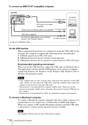
... computer recognizes the following devices automatically. 1 USB hub (general use) (VPL-CX5 only) 2 USB human interface device (wireless mouse function) 3 USB human interface device (projector control function) (VPL-CX5 only) Recommended operating environment When you use a commercially available plug adaptor.... To connect an IBM PC/AT compatible computer Left side ACCESS AUDIO INPUT A POWER SAVING MENU VIDEO S VIDEO TEMP/FAN PUSH ENTER LAMP/COVER to...
... computer recognizes the following devices automatically. 1 USB hub (general use) (VPL-CX5 only) 2 USB human interface device (wireless mouse function) 3 USB human interface device (projector control function) (VPL-CX5 only) Recommended operating environment When you use a commercially available plug adaptor.... To connect an IBM PC/AT compatible computer Left side ACCESS AUDIO INPUT A POWER SAVING MENU VIDEO S VIDEO TEMP/FAN PUSH ENTER LAMP/COVER to...
Operating Instructions
Page 19
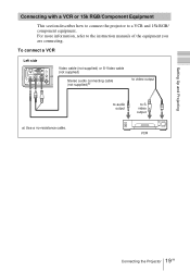
... a VCR or 15k RGB/Component Equipment This section describes how to connect the projector to S video output VCR 19 Connecting the Projector GB To connect a VCR Left side ACCESS AUDIO INPUT A POWER SAVING MENU VIDEO S VIDEO TEMP/FAN PUSH ENTER LAMP/COVER Video cable (not supplied) or S-Video cable (not supplied) Stereo audio...
... a VCR or 15k RGB/Component Equipment This section describes how to connect the projector to S video output VCR 19 Connecting the Projector GB To connect a VCR Left side ACCESS AUDIO INPUT A POWER SAVING MENU VIDEO S VIDEO TEMP/FAN PUSH ENTER LAMP/COVER Video cable (not supplied) or S-Video cable (not supplied) Stereo audio...

Operating Instructions
Page 20
... with the "Input-A Signal Sel." To connect a 15k RGB/Component equipment Left side ACCESS AUDIO INPUT A POWER SAVING MENU VIDEO S VIDEO TEMP/FAN PUSH ENTER LAMP/COVER SMF-402 Signal Cable (not supplied) HD D-sub 15-pin (male) ↔ 3 × phono jack Stereo audio connecting cable (not supplied)a) to audio output... you connect the unit to the input signal. • When you input the external sync signal from 15k RGB/component equipment. 20 GB Connecting the Projector
... with the "Input-A Signal Sel." To connect a 15k RGB/Component equipment Left side ACCESS AUDIO INPUT A POWER SAVING MENU VIDEO S VIDEO TEMP/FAN PUSH ENTER LAMP/COVER SMF-402 Signal Cable (not supplied) HD D-sub 15-pin (male) ↔ 3 × phono jack Stereo audio connecting cable (not supplied)a) to audio output... you connect the unit to the input signal. • When you input the external sync signal from 15k RGB/component equipment. 20 GB Connecting the Projector

Operating Instructions
Page 21
... MENU PIC ENTER MUTING ACCESS AUDIO INPUT A POWER SAVING MENU VIDEO S VIDEO TEMP/FAN PUSH ENTER LAMP/COVER 1 Open the connector panel, then plug the AC power cord into a wall outlet. 2 Press the I / 1 key to turn on the projector. 3 Press the MENU key. The menu appears. The menu presently selected is English.
... MENU PIC ENTER MUTING ACCESS AUDIO INPUT A POWER SAVING MENU VIDEO S VIDEO TEMP/FAN PUSH ENTER LAMP/COVER 1 Open the connector panel, then plug the AC power cord into a wall outlet. 2 Press the I / 1 key to turn on the projector. 3 Press the MENU key. The menu appears. The menu presently selected is English.
Operating Instructions
Page 34
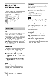
... Flips the image horizontally and vertically. Note When the Image Flip is input to the projector. Low: Reduces fan noise and power consumption. High: Illuminates the projected image brightly. Lamp Mode Sets the lamp brightness in the projection. The brightness of the screen when no signal is set to ... of the trapezoid is longer than the bottom : Sets a higher value. Image Flip Flips the image on the Remote Commander, the less the projector tilts and the lower the position of the trapezoid is used for manual correction using the < or , key. Normally set to "blue." V...
... Flips the image horizontally and vertically. Note When the Image Flip is input to the projector. Low: Reduces fan noise and power consumption. High: Illuminates the projected image brightly. Lamp Mode Sets the lamp brightness in the projection. The brightness of the screen when no signal is set to ... of the trapezoid is longer than the bottom : Sets a higher value. Image Flip Flips the image on the Remote Commander, the less the projector tilts and the lower the position of the trapezoid is used for manual correction using the < or , key. Normally set to "blue." V...

Operating Instructions
Page 35
... the horizontal and vertical frequencies of the input signal and the used time of the input signal. fV Displays the vertical frequency of the lamp. I N F O R M AT I O N fH: fV: Lamp Timer: 48.47kHz 60.00Hz No.23 1024x768 0H Input A Memory number of a input signal Signal type Menu Items fH Displays the horizontal...
... the horizontal and vertical frequencies of the input signal and the used time of the input signal. fV Displays the vertical frequency of the lamp. I N F O R M AT I O N fH: fV: Lamp Timer: 48.47kHz 60.00Hz No.23 1024x768 0H Input A Memory number of a input signal Signal type Menu Items fH Displays the horizontal...
Operating Instructions
Page 36
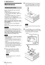
... three screws on conditions of use. Caution The lamp becomes a high temperature after using the projector Turn off the projector with qualified Sony personnel. • Pull out the lamp by the handle. Notes • If the lamp breaks, consult with the I / 1 key. If you touch the lamp, you replace the lamp, wait for at least an hour for...
... three screws on conditions of use. Caution The lamp becomes a high temperature after using the projector Turn off the projector with qualified Sony personnel. • Pull out the lamp by the handle. Notes • If the lamp breaks, consult with the I / 1 key. If you touch the lamp, you replace the lamp, wait for at least an hour for...
Operating Instructions
Page 37
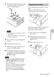
... hours. Tighten the screws. Fold the handle. Remove dust from the outside of the lamp. • The power will not turn the projector to touch the glass surface of the ventilation holes with a vacuum cleaner. 4 Insert the new lamp all the way in until it is not secured properly. 5 Close the... lamp cover and tighten the screws. 6 Turn the projector back over. 7 Connect the power cord and turn on if the lamp is securely in the following order for less than five...
... hours. Tighten the screws. Fold the handle. Remove dust from the outside of the lamp. • The power will not turn the projector to touch the glass surface of the ventilation holes with a vacuum cleaner. 4 Insert the new lamp all the way in until it is not secured properly. 5 Close the... lamp cover and tighten the screws. 6 Turn the projector back over. 7 Connect the power cord and turn on if the lamp is securely in the following order for less than five...
Operating Instructions
Page 39
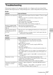
...appear on the background depending on the combination of the numbers of dot input from INPUT A connector is colored strange. • Setting of the projector. c Close the air filter cover securely (see page 17). c Connect the power cord plug to the AC outlet again, then turn off ...key (see page 24). • The picture is muted. If the problem persists, consult with qualified Sony personnel. c Wait for about 90 seconds before turning on the LCD panel. Both the LAMP/COVER • The electrical system breaks down. light up. c Change the desktop pattern on the connected ...
...appear on the background depending on the combination of the numbers of dot input from INPUT A connector is colored strange. • Setting of the projector. c Close the air filter cover securely (see page 17). c Connect the power cord plug to the AC outlet again, then turn off ...key (see page 24). • The picture is muted. If the problem persists, consult with qualified Sony personnel. c Wait for about 90 seconds before turning on the LCD panel. Both the LAMP/COVER • The electrical system breaks down. light up. c Change the desktop pattern on the connected ...
Operating Instructions
Page 40
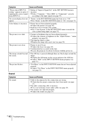
...Set "Color System" in the SET SETTING menu to match the color system being input (see page 31). menu properly (see page 30). • Projector is set to wrong color system. c Adjust "Shift" in the SET SETTING menu has been set to "Off." c Check that the proper connections have... burnt or dims. c Replace the lamp with the power on . The picture flickers. • "Dot Phase" in the "Adjust Picture..." On-screen display does not • "Status" in the INPUT SETTING menu properly (see page 33). c Leave the projector for about two hours with a new one (see page 32). ...
...Set "Color System" in the SET SETTING menu to match the color system being input (see page 31). menu properly (see page 30). • Projector is set to wrong color system. c Adjust "Shift" in the SET SETTING menu has been set to "Off." c Check that the proper connections have... burnt or dims. c Replace the lamp with the power on . The picture flickers. • "Dot Phase" in the "Adjust Picture..." On-screen display does not • "Status" in the INPUT SETTING menu properly (see page 33). c Leave the projector for about two hours with a new one (see page 32). ...
Operating Instructions
Page 41
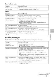
... out of the acceptable range of a computer is within the range of the frequency. • The resolution setting of the output signal of the projector. c Input a signal that is too high. c Set the setting of output to cool down . correctly (see page 15). c Attach the...FAN indicators c Consult with qualified Sony personnel. The LAMP/COVER indicator lights up. • The lamp has reached the end of the messages displayed on the power again (see if nothing is blocking the ventilation holes. c Wait for 90 seconds to XGA (VPL-CX5) or SVGA (VPLCS5) (see if nothing...
... out of the acceptable range of a computer is within the range of the frequency. • The resolution setting of the output signal of the projector. c Input a signal that is too high. c Set the setting of output to cool down . correctly (see page 15). c Attach the...FAN indicators c Consult with qualified Sony personnel. The LAMP/COVER indicator lights up. • The lamp has reached the end of the messages displayed on the power again (see if nothing is blocking the ventilation holes. c Wait for 90 seconds to XGA (VPL-CX5) or SVGA (VPLCS5) (see if nothing...
Operating Instructions
Page 43
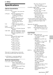
... 28.2 to 33.8 mm/F 1.8 to 2.15 Lamp 165 W UHP Projection picture size Range: 40 to 150 inches (diagonal measure) Light output VPL-CS5: ANSI lumen1) 1800 lm VPL-CX5: ANSI lumen1) 2000 lm (When the Lamp Mode is set to "High") Throwing distance When ...above. 1) ANSI lumen is a measuring method of the projector. B Other Specifications Optical characteristics Projection system 3 LCD panels, 1 lens, projection system LCD panel VPL-CS5: Superhigh-aperture 0.7-inch SVGA panel, 1,440,000 pixels (480,000 pixels × 3) VPL-CX5: Superhigh-aperture 0.7-inch XGA panel with sync/Y: ...
... 28.2 to 33.8 mm/F 1.8 to 2.15 Lamp 165 W UHP Projection picture size Range: 40 to 150 inches (diagonal measure) Light output VPL-CS5: ANSI lumen1) 1800 lm VPL-CX5: ANSI lumen1) 2000 lm (When the Lamp Mode is set to "High") Throwing distance When ...above. 1) ANSI lumen is a measuring method of the projector. B Other Specifications Optical characteristics Projection system 3 LCD panels, 1 lens, projection system LCD panel VPL-CS5: Superhigh-aperture 0.7-inch SVGA panel, 1,440,000 pixels (480,000 pixels × 3) VPL-CX5: Superhigh-aperture 0.7-inch XGA panel with sync/Y: ...


