
VGC-RBxx Series Hard Disk Drive Replacement Instructions
Page 1
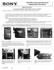
...you begin work to avoid scratching the surface of your desktop computer.* ü Place your desktop computer on both sides of the computer under these procedures. Disconnect the power cord. Failure to do so can result in damage to the computer's case. * ü Follow the ESD (Electrostatic Discharge...remove the two (2) indicated screws from the components shipped. VGC-RBxx Series Hard Disk Drive Replacement Instructions IMPORTANT! Pull with your Sony Limited Warranty continue to initiate removal of the arrow. Locate the power cable [1] and serial ATA cable [2]. Remove the panel and...
...you begin work to avoid scratching the surface of your desktop computer.* ü Place your desktop computer on both sides of the computer under these procedures. Disconnect the power cord. Failure to do so can result in damage to the computer's case. * ü Follow the ESD (Electrostatic Discharge...remove the two (2) indicated screws from the components shipped. VGC-RBxx Series Hard Disk Drive Replacement Instructions IMPORTANT! Pull with your Sony Limited Warranty continue to initiate removal of the arrow. Locate the power cable [1] and serial ATA cable [2]. Remove the panel and...
VGC-RBxx Series Hard Disk Drive Replacement Instructions
Page 2
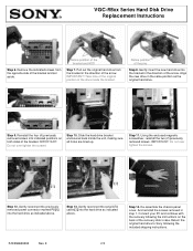
.... Do not over tighten the screws. [2] [1] Step 12. Gently reconnect the previously removed power connector marked P8 [1] into the hard drive as indicated above . Return the original hard drive to Sony following the instructions on both sides of the recovery disk's case. Remove the indicated screws from... the bracket in the direction of the bracket and set aside. Align the new drive in step 1. Step 10. VGC-RBxx Series Hard Disk Drive ...
.... Do not over tighten the screws. [2] [1] Step 12. Gently reconnect the previously removed power connector marked P8 [1] into the hard drive as indicated above . Return the original hard drive to Sony following the instructions on both sides of the recovery disk's case. Remove the indicated screws from... the bracket in the direction of the bracket and set aside. Align the new drive in step 1. Step 10. VGC-RBxx Series Hard Disk Drive ...
VGC-RBxx Series Optical Disk Drive Lower Replacement Instructions
Page 1
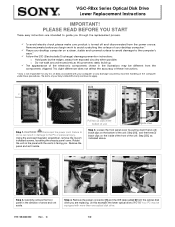
... scratching the surface of your desktop computer on a clean, stable and covered surface to avoid damage to apply. 2 Screws [2A] [2B] Step 1. Pull two (2) clips at the bottom of the computer under these instructions. * Sony is facing you. Loosen the front panel cover by the edges, away from the power source. Your PC may be...
... scratching the surface of your desktop computer on a clean, stable and covered surface to avoid damage to apply. 2 Screws [2A] [2B] Step 1. Pull two (2) clips at the bottom of the computer under these instructions. * Sony is facing you. Loosen the front panel cover by the edges, away from the power source. Your PC may be...
VGC-RBxx Series Optical Disk Drive Lower Replacement Instructions
Page 2
... example: the lower optical drive.) IMPORTANT! Reconnect the IDE data cable [ 1] and the power cable [2] to its original position , as shown. Reinstall the left chassis cover panel in ... Step 6. Do not over tighten the screw s! Return the original optical disk drive to Sony following the included shipping instructions P/N 994630200 Rev. Step 11. Do not over tighten the...slide the new optical drive into the newly vacant space in the direction of the arrow. VGC-RBxx Series Optical Disk Drive Lower Replacement Instructions Step 5. IMPORTANT! Using the enclosed magnetic screwdriver...
... example: the lower optical drive.) IMPORTANT! Reconnect the IDE data cable [ 1] and the power cable [2] to its original position , as shown. Reinstall the left chassis cover panel in ... Step 6. Do not over tighten the screw s! Return the original optical disk drive to Sony following the included shipping instructions P/N 994630200 Rev. Step 11. Do not over tighten the...slide the new optical drive into the newly vacant space in the direction of the arrow. VGC-RBxx Series Optical Disk Drive Lower Replacement Instructions Step 5. IMPORTANT! Using the enclosed magnetic screwdriver...
VGC-RBxx Series Optical Disk Drive Upper Replacement Instructions
Page 1
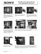
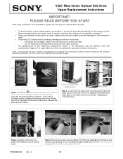
...power source. Remove the power connector [1] and the IDE data cable [ 2] from exposed circuitry when possible. Your PC may be equipped with your computer or any damage caused by the edges, away from the optical disk drive you begin work to avoid scratching the surface of your desktop computer.* ü Place your Sony...promotes static build-up. ü The appearance of the computer under these instructions. * Sony is turned off and disconnected from the components shipped. The terms of unit. VGC-RBxx Series Optical Disk Drive Upper Replacement Instructions IMPORTANT! ...
...power source. Remove the power connector [1] and the IDE data cable [ 2] from exposed circuitry when possible. Your PC may be equipped with your computer or any damage caused by the edges, away from the optical disk drive you begin work to avoid scratching the surface of your desktop computer.* ü Place your Sony...promotes static build-up. ü The appearance of the computer under these instructions. * Sony is turned off and disconnected from the components shipped. The terms of unit. VGC-RBxx Series Optical Disk Drive Upper Replacement Instructions IMPORTANT! ...
VGC-RBxx Series Optical Disk Drive Upper Replacement Instructions
Page 2
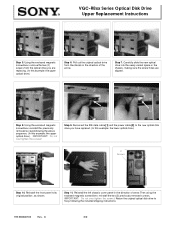
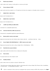
... chassis in the direction of the arrow. Reconnect the IDE data cable [ 1] and the power cable [2] to the new optical disk drive you are aligned. 2 1 [1] [2] Step 8. C 2/2 Reinstall the front panel to Sony following the included shipping instructions P/N 994630100 Rev. VGC-RBxx Series Optical Disk Drive Upper Replacement Instructions Step 5. Step 7. Step 9. Reinstall the...
... chassis in the direction of the arrow. Reconnect the IDE data cable [ 1] and the power cable [2] to the new optical disk drive you are aligned. 2 1 [1] [2] Step 8. C 2/2 Reinstall the front panel to Sony following the included shipping instructions P/N 994630100 Rev. VGC-RBxx Series Optical Disk Drive Upper Replacement Instructions Step 5. Step 7. Step 9. Reinstall the...

Safety Information
Page 3
...model and serial numbers when you call your local authorities or the Electronics Industries Alliance at http://esupport.sony.com/EN/VAIO/. See the online specifications sheet for the Sony Service Center nearest you have purchased. For customers in a secure location. The program backs the development...Disposal of this product meets the ENERGY STAR® guidelines for energy efficiency. registered trademark of products with all VAIO® computer models) Carrier frequency Output power 27.045 MHz Less than 100 nW 3 Record the model and serial number in the space provided here, and...
...model and serial numbers when you call your local authorities or the Electronics Industries Alliance at http://esupport.sony.com/EN/VAIO/. See the online specifications sheet for the Sony Service Center nearest you have purchased. For customers in a secure location. The program backs the development...Disposal of this product meets the ENERGY STAR® guidelines for energy efficiency. registered trademark of products with all VAIO® computer models) Carrier frequency Output power 27.045 MHz Less than 100 nW 3 Record the model and serial number in the space provided here, and...
User Guide
Page 9
... memory card reader Reads and writes data from and to designate that a product contains an IEEE 1394 connection. i.LINK is a trademark of Sony used only to a Secure Digital (SD) or MultiMediaCard (MMC). 13 Hard disk drive access indicator Light is amber while the hard disk ...CompactFlash®/Microdrive slots. 5 Media access indicator1 Light is amber when reading or writing data to a memory card reader. 6 Power indicator (VAIO) Light is white when the computer is on /off. 15 Standby indicator Light is amber when the computer is placed in Standby mode or turned off when the...
... memory card reader Reads and writes data from and to designate that a product contains an IEEE 1394 connection. i.LINK is a trademark of Sony used only to a Secure Digital (SD) or MultiMediaCard (MMC). 13 Hard disk drive access indicator Light is amber while the hard disk ...CompactFlash®/Microdrive slots. 5 Media access indicator1 Light is amber when reading or writing data to a memory card reader. 6 Power indicator (VAIO) Light is white when the computer is on /off. 15 Standby indicator Light is amber when the computer is placed in Standby mode or turned off when the...

User Guide
Page 11
Page 11 Back panel The available ports and jacks on your computer contains the ports for supplied and optional accessories. Back panel 1 AC Input port Connection for the supplied power cord. 2 Mouse port Connection for a PS/2® mouse. 3 Keyboard port Connection for a PS/2 keyboard. 4 Printer port Connection for details on hardware configuration. About...
Page 11 Back panel The available ports and jacks on your computer contains the ports for supplied and optional accessories. Back panel 1 AC Input port Connection for the supplied power cord. 2 Mouse port Connection for a PS/2® mouse. 3 Keyboard port Connection for a PS/2 keyboard. 4 Printer port Connection for details on hardware configuration. About...

User Guide
Page 12
... cable (optional). 9 Modem line jack3 Connection for an RJ-11 telephone cable (optional). 10 i.LINK 6-pin S400 port (IEEE 1394) Connection and power for a compatible digital device, such as a Sony Digital Handycam® camcorder. 11 Ethernet port Connection for a 10BASE-T/100BASE-TX/1000BASE-T Ethernet. (The port marked with (Network) is for LAN...
... cable (optional). 9 Modem line jack3 Connection for an RJ-11 telephone cable (optional). 10 i.LINK 6-pin S400 port (IEEE 1394) Connection and power for a compatible digital device, such as a Sony Digital Handycam® camcorder. 11 Ethernet port Connection for a 10BASE-T/100BASE-TX/1000BASE-T Ethernet. (The port marked with (Network) is for LAN...

User Guide
Page 16
... set up , down, left, and right arrow keys move the pointer on the taskbar. AlwPaaygseu1s6e Standby Places the computer in the Windows® taskbar notification area. Pressing this key is equivalent to reduce power consumption. BUTTON DESCRIPTION Volume Increases (+) and decreases (-) the volume. Press the Num Lock key to activate the numeric...
... set up , down, left, and right arrow keys move the pointer on the taskbar. AlwPaaygseu1s6e Standby Places the computer in the Windows® taskbar notification area. Pressing this key is equivalent to reduce power consumption. BUTTON DESCRIPTION Volume Increases (+) and decreases (-) the volume. Press the Num Lock key to activate the numeric...

User Guide
Page 18
... or to resume normal operation. Directional Arrows The Up, Down, Left, and Right arrow keys move the pointer on the screen. Press the Power button or any key briefly, to perform basic math calculations. Press the Mute button again to perform certain tasks. About the Keyboard (wired) Your...next. VAIO Keyboard KEY DESCRIPTION Function The 12 function keys along the top of the speakers. Press the button to deactivate the numeric keypad. Press the Num Lock key to activate the numeric keypad. (The Num Lock indicator lights.) Press the Num Lock key again to place the computer in ...
... or to resume normal operation. Directional Arrows The Up, Down, Left, and Right arrow keys move the pointer on the screen. Press the Power button or any key briefly, to perform basic math calculations. Press the Mute button again to perform certain tasks. About the Keyboard (wired) Your...next. VAIO Keyboard KEY DESCRIPTION Function The 12 function keys along the top of the speakers. Press the button to deactivate the numeric keypad. Press the Num Lock key to activate the numeric keypad. (The Num Lock indicator lights.) Press the Num Lock key again to place the computer in ...

User Guide
Page 20
... Wireless m ouse (Side and bottom ) 1 Power switch Slide power switch to turn the mouse on the LCD screen. 3 Right mouse button Press to enable communication between your computer, see the section, Connecting the Wireless Optical Mouse. About the Wireless Mouse Your VAIO® computer may be supplied with your VAIO® computer and the wireless mouse. Before...
... Wireless m ouse (Side and bottom ) 1 Power switch Slide power switch to turn the mouse on the LCD screen. 3 Right mouse button Press to enable communication between your computer, see the section, Connecting the Wireless Optical Mouse. About the Wireless Mouse Your VAIO® computer may be supplied with your VAIO® computer and the wireless mouse. Before...

User Guide
Page 21
...batteries to be replaced. Inserting batteries into the wireless mouse as shown. When your wireless mouse is not being used /new batteries can check your computer's specifications sheet for extended periods of battery. Insert two AA batteries (supplied) into the wireless m ouse If your wireless mouse does not operate properly..., the batteries may need to avoid possible damage from battery leakage. 1See your mouse's battery power level by clicking (wireless mouse icon), located in the wireless mouse. You can damage the mouse.
...batteries to be replaced. Inserting batteries into the wireless mouse as shown. When your wireless mouse is not being used /new batteries can check your computer's specifications sheet for extended periods of battery. Insert two AA batteries (supplied) into the wireless m ouse If your wireless mouse does not operate properly..., the batteries may need to avoid possible damage from battery leakage. 1See your mouse's battery power level by clicking (wireless mouse icon), located in the wireless mouse. You can damage the mouse.

User Guide
Page 22
... on or off. 2 CONNECT button Press to perform specific mouse functions. About the Wireless Mouse Your VAIO® computer may be supplied with your VAIO® computer and the wireless mouse. Wireless m ouse (Side and bottom ) 1 Power switch Slide power switch to turn the mouse on the LCD screen. 3 Right mouse button Press to enable communication...
... on or off. 2 CONNECT button Press to perform specific mouse functions. About the Wireless Mouse Your VAIO® computer may be supplied with your VAIO® computer and the wireless mouse. Wireless m ouse (Side and bottom ) 1 Power switch Slide power switch to turn the mouse on the LCD screen. 3 Right mouse button Press to enable communication...

User Guide
Page 23
You can damage the mouse. Insert two AA batteries (supplied) into the wireless m ouse If your computer's specifications sheet for extended periods of battery. When your wireless mouse is not being used for details about supplied accessories. Using incompatible batteries or mixing ... does not operate properly, the batteries may need to be replaced. Page 23 Do not mix old (used /new batteries can check your mouse's battery power level by clicking (wireless mouse icon), located in the wireless mouse. Inserting batteries into the wireless mouse as shown.
You can damage the mouse. Insert two AA batteries (supplied) into the wireless m ouse If your computer's specifications sheet for extended periods of battery. When your wireless mouse is not being used for details about supplied accessories. Using incompatible batteries or mixing ... does not operate properly, the batteries may need to be replaced. Page 23 Do not mix old (used /new batteries can check your mouse's battery power level by clicking (wireless mouse icon), located in the wireless mouse. Inserting batteries into the wireless mouse as shown.

User Guide
Page 26
... OK to activate the channel selection.) 9 CLEAR button Use to backspace and delete entered text. 10 STANDBY button Press to place the computer in Stand by mode to reduce power consumption. 11 MY PICTURES button Press to view pictures or a slide show. 12 MY VIDEOS button Press to view videos from your...
... OK to activate the channel selection.) 9 CLEAR button Use to backspace and delete entered text. 10 STANDBY button Press to place the computer in Stand by mode to reduce power consumption. 11 MY PICTURES button Press to view pictures or a slide show. 12 MY VIDEOS button Press to view videos from your...

User Guide
Page 28
... Plug the i.LINK cable connector into the corresponding 4- Connecting an i.LINK (IEEE 1394) device 1. or 6-pin i.LINK port on your computer. A 6-pin i.LINK port can supply power (10V to 12V) to a connected i.LINK device, if the device is equipped with a 4-pin and a 6-pin i.LINK® port...Plug the other end of the cable into this port. 2. The total power supplied by the 6-pin i.LINK port does not exceed 6 watts. See the instructions supplied with a 6-pin connector. About the i.LINK Port Your VAIO® computer is equipped with your i.LINK device for more information on your...
... Plug the i.LINK cable connector into the corresponding 4- Connecting an i.LINK (IEEE 1394) device 1. or 6-pin i.LINK port on your computer. A 6-pin i.LINK port can supply power (10V to 12V) to a connected i.LINK device, if the device is equipped with a 4-pin and a 6-pin i.LINK® port...Plug the other end of the cable into this port. 2. The total power supplied by the 6-pin i.LINK port does not exceed 6 watts. See the instructions supplied with a 6-pin connector. About the i.LINK Port Your VAIO® computer is equipped with your i.LINK device for more information on your...

User Guide
Page 29
...) Speaker Systems Configuring Software for Your Speaker System Configuring Software for Your Speaker System Connecting the Power Cords Turning On Your Computer Page 29 Setting Up Your Computer Your computer may vary from the illustrations shown in the section. The location of the controls, ports, and jacks may not be...
...) Speaker Systems Configuring Software for Your Speaker System Configuring Software for Your Speaker System Connecting the Power Cords Turning On Your Computer Page 29 Setting Up Your Computer Your computer may vary from the illustrations shown in the section. The location of the controls, ports, and jacks may not be...

User Guide
Page 30
To connect a display Install your equipment so that you can easily reach the power outlet in the event of the display. See the specifications sheet for your computer on the model purchased. If necessary, plug the display's cable into the appropriate monitor port. 2. Plug the display's cable into the rear of an emergency. Page 30 Connecting a Display (Monitor) The location, availability, and type of the monitor port may vary, depending on the Sony Online Support Web site at http://www.sony.com/pcsupport, for details about your computer's hardware configuration 1.
To connect a display Install your equipment so that you can easily reach the power outlet in the event of the display. See the specifications sheet for your computer on the model purchased. If necessary, plug the display's cable into the appropriate monitor port. 2. Plug the display's cable into the rear of an emergency. Page 30 Connecting a Display (Monitor) The location, availability, and type of the monitor port may vary, depending on the Sony Online Support Web site at http://www.sony.com/pcsupport, for details about your computer's hardware configuration 1.

