Operating Instructions
Page 11
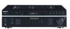
Direct tuning 1 2 3 4 bbbb bbb Storing FM stations automatically (Models of area code CEL, CEK only) 1 ?/1 2 ?/1 If you cannot tune in a station and the entered numbers flash Notes ?/1 11GB
Direct tuning 1 2 3 4 bbbb bbb Storing FM stations automatically (Models of area code CEL, CEK only) 1 ?/1 2 ?/1 If you cannot tune in a station and the entered numbers flash Notes ?/1 11GB
Operating Instructions
Page 13
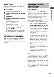
Using the Radio Data System (RDS) (Models of area code CEL, CEK only) Displaying RDS information Notes t t t t Notes Receiving RDS broadcasts Note 13GB
Using the Radio Data System (RDS) (Models of area code CEL, CEK only) Displaying RDS information Notes t t t t Notes Receiving RDS broadcasts Note 13GB

Operating Instructions
Page 16
Other Operations Naming preset stations and inputs Tips t t 1 To index a preset station To index an input 2 3 4 Note (Models of area code CEL, CEK only) 16GB
Other Operations Naming preset stations and inputs Tips t t 1 To index a preset station To index an input 2 3 4 Note (Models of area code CEL, CEK only) 16GB
Operating Instructions
Page 26
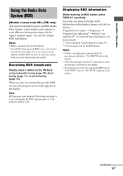
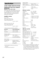
Specifications AUDIO POWER SPECIFICATIONS POWER OUTPUT AND TOTAL HARMONIC DISTORTION: (Models of area code U only) FM tuner section Amplifier section AM tuner section ?/1 26GB
Specifications AUDIO POWER SPECIFICATIONS POWER OUTPUT AND TOTAL HARMONIC DISTORTION: (Models of area code U only) FM tuner section Amplifier section AM tuner section ?/1 26GB

Service Manual
Page 1
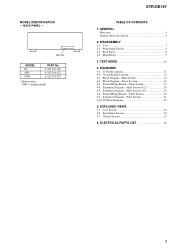
Continued on next page - FM STEREO/FM-AM RECEIVER 9-877-864-06 2007E04-1 © 2007. 05 Sony Corporation Home Audio Division Published by Sony Techno Create Corporation 1 rated 100 watts per channel minimum RMS power, with bass boost and tone b ypassed). 3) ...only) With 8 ohm loads, both channels driven, from 250 milliwatts to rated output. SERVICE MANUAL Ver. 1.5 2007. 05 STR-DE197 US Model Canadian Model AEP Model AUDIO POWER SPECIFICATIONS POWER OUTPUT AND TOTAL HARMONIC DISTORTION: (Models of ar ea code AEP Power Output a t Ster eo Mode (8 ohms 1 kHz, THD 0.7 %) 100 W + ...
Continued on next page - FM STEREO/FM-AM RECEIVER 9-877-864-06 2007E04-1 © 2007. 05 Sony Corporation Home Audio Division Published by Sony Techno Create Corporation 1 rated 100 watts per channel minimum RMS power, with bass boost and tone b ypassed). 3) ...only) With 8 ohm loads, both channels driven, from 250 milliwatts to rated output. SERVICE MANUAL Ver. 1.5 2007. 05 STR-DE197 US Model Canadian Model AEP Model AUDIO POWER SPECIFICATIONS POWER OUTPUT AND TOTAL HARMONIC DISTORTION: (Models of ar ea code AEP Power Output a t Ster eo Mode (8 ohms 1 kHz, THD 0.7 %) 100 W + ...

Service Manual
Page 2
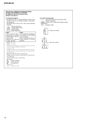
...MARQUE 0 SUR LES DIAGRAMMES SCHÉMATIQUES ET LA LISTE DES PIÈCES SONT CRITIQUES POUR LA SÉCURITÉ DE FONCTIONNEMENT. STR-DE197 AM tuner section Tuning range Models of area code US, CND With 10-kHz tuning scale: 530 - 1,710 kHz 4) With 9-kHz tuning scale: 531 - 1,710 ...CE MANUEL OU DANS LES SUPPLÉMENTS PUBLIÉS PAR SONY. A battery-operated AC milliammeter. The Data Precision 245 digital multimeter is suitable for AC leakage. Measuring the voltage drop across a resistor by any AM station, turn off the receiver. Hold down PRESET TUNING + and press ?/1. A) To ...
...MARQUE 0 SUR LES DIAGRAMMES SCHÉMATIQUES ET LA LISTE DES PIÈCES SONT CRITIQUES POUR LA SÉCURITÉ DE FONCTIONNEMENT. STR-DE197 AM tuner section Tuning range Models of area code US, CND With 10-kHz tuning scale: 530 - 1,710 kHz 4) With 9-kHz tuning scale: 531 - 1,710 ...CE MANUEL OU DANS LES SUPPLÉMENTS PUBLIÉS PAR SONY. A battery-operated AC milliammeter. The Data Precision 245 digital multimeter is suitable for AC leakage. Measuring the voltage drop across a resistor by any AM station, turn off the receiver. Hold down PRESET TUNING + and press ?/1. A) To ...
Service Manual
Page 3
... AEP CND PART No. 4-253-299-0s 4-253-299-1s 4-253-299-3s • Abbreviation CND: Canadian model STR-DE197 TABLE OF CONTENTS 1. Schematic Diagram - Case Section 23 5-2. MODEL IDENTIFICATION - Block Diagram - Schematic Diagram - Front Panel Section 8 2-3. Back Panel 8 2-4. Main Section (2/2 19 4-8. Panel Section 21 4-10. Panel Section 20 4-9. GENERAL Main unit 4 Remote button...
... AEP CND PART No. 4-253-299-0s 4-253-299-1s 4-253-299-3s • Abbreviation CND: Canadian model STR-DE197 TABLE OF CONTENTS 1. Schematic Diagram - Case Section 23 5-2. MODEL IDENTIFICATION - Block Diagram - Schematic Diagram - Front Panel Section 8 2-3. Back Panel 8 2-4. Main Section (2/2 19 4-8. Panel Section 21 4-10. Panel Section 20 4-9. GENERAL Main unit 4 Remote button...

Service Manual
Page 10
... scrolled for a moment. AUTO-BETICAL Check Mode (AEP model) To auto-scanning and memories of function buttons all light off 3. The message "AUTO-BETICAL SELECT" are displayed for a moment and the receiver starts scanning. ING/CHAR +] button, press the ?/1 button...model : U *.** AEP model : CE *.** Software version Area 10 While depressing the [VIDEO 1], [VIDEO 2], [MD/TAPE], [CD] and the [TUNER] buttons simultaneously, press the ?/1 button to turn on the main power. 2. Either the message "9k STEP" or "10k STEP" appears for the AM tuning interval. Procedure: 1. STR-DE197...
... scrolled for a moment. AUTO-BETICAL Check Mode (AEP model) To auto-scanning and memories of function buttons all light off 3. The message "AUTO-BETICAL SELECT" are displayed for a moment and the receiver starts scanning. ING/CHAR +] button, press the ?/1 button...model : U *.** AEP model : CE *.** Software version Area 10 While depressing the [VIDEO 1], [VIDEO 2], [MD/TAPE], [CD] and the [TUNER] buttons simultaneously, press the ?/1 button to turn on the main power. 2. Either the message "9k STEP" or "10k STEP" appears for the AM tuning interval. Procedure: 1. STR-DE197...

Service Manual
Page 11
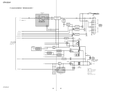
...model, L: AEP model) FM/AM signal meter voltage detection signal input from remote control receiver IC. 50 TUNER MUTE O Muting control signal output to sound control IC. 15 RDS DATA I RDS data signal input from FM/AM tuner pack. (AEP model... VERSION I Master volume JOG data input A, B 40 FUNC.MUTE O Not used . (Connect to AV.REF pin in this set ) 41 CK O Serial clock signal output to electronic volume IC. 42...AM tuner pack. (AEP model only) 47 STOP I STEREO indicator detection signal input from reset/+5.6V regulator IC. 48 VSS - SECTION 4 DIAGRAMS STR-DE197 4-1.
...model, L: AEP model) FM/AM signal meter voltage detection signal input from remote control receiver IC. 50 TUNER MUTE O Muting control signal output to sound control IC. 15 RDS DATA I RDS data signal input from FM/AM tuner pack. (AEP model... VERSION I Master volume JOG data input A, B 40 FUNC.MUTE O Not used . (Connect to AV.REF pin in this set ) 41 CK O Serial clock signal output to electronic volume IC. 42...AM tuner pack. (AEP model only) 47 STOP I STEREO indicator detection signal input from reset/+5.6V regulator IC. 48 VSS - SECTION 4 DIAGRAMS STR-DE197 4-1.
Service Manual
Page 14
...specified. • f : internal component. • 2 : nonflammable resistor. • 1 : fusible resistor. • C : panel designation. STR-DE197 THIS NOTE IS COMMON FOR PRINTED WIRING BOARDS AND SCHEMATIC DIAGRAMS. (In addition to normal production tolerances. • Waveforms are taken with mark 0 are... : B+ Line. • B : B- F : TUNER (FM/AM) L : VIDEO (AUDIO) J : CD (ANALOG) • Abbreviation CND : Canadian model. Line. • Voltage and waveforms are dc with a VOM (Input impedance 10 MΩ). no -signal (detuned) conditions. BE Q BCE Q BCE These are ...
...specified. • f : internal component. • 2 : nonflammable resistor. • 1 : fusible resistor. • C : panel designation. STR-DE197 THIS NOTE IS COMMON FOR PRINTED WIRING BOARDS AND SCHEMATIC DIAGRAMS. (In addition to normal production tolerances. • Waveforms are taken with mark 0 are... : B+ Line. • B : B- F : TUNER (FM/AM) L : VIDEO (AUDIO) J : CD (ANALOG) • Abbreviation CND : Canadian model. Line. • Voltage and waveforms are dc with a VOM (Input impedance 10 MΩ). no -signal (detuned) conditions. BE Q BCE Q BCE These are ...

Service Manual
Page 15
... 7 VOL L 29 MD L 5 VIDEO 2 3 TREBLE L MIDDLE L BASS L OUT L 20 VIDEO 1 1 CONTROL 15 14 CLK DATA CLK DATA STB STR-DE197 AUDIO AMP IC403 3 1 ELECTRONIC VOLUME IC402 L 3 IN L OUT 2 VOLUME CONTROL 8 9 10 VIDEO 1,MD/TAPE SELECT IC404 1 2 4 3 13 5...VOL B X1 X2 SIRCS 38 39 13 RV201 MASTER VOLUME 34 35 49 71 X201 4.19MHz 1 REMOTE CONTROL RECEIVER IC202 -24V 77 - 72,70 - 62 7 - 1,80 - 78 FL201 VACUUM FLUORESCENT DISPLAY F1 F2 ... is omitted due to same as L-ch. • Abbreviation CND : Canadian model STR-DE197 15 15 Q424 INV. 4-3. MAIN SECTION - BLOCK DIAGRAM -
... 7 VOL L 29 MD L 5 VIDEO 2 3 TREBLE L MIDDLE L BASS L OUT L 20 VIDEO 1 1 CONTROL 15 14 CLK DATA CLK DATA STB STR-DE197 AUDIO AMP IC403 3 1 ELECTRONIC VOLUME IC402 L 3 IN L OUT 2 VOLUME CONTROL 8 9 10 VIDEO 1,MD/TAPE SELECT IC404 1 2 4 3 13 5...VOL B X1 X2 SIRCS 38 39 13 RV201 MASTER VOLUME 34 35 49 71 X201 4.19MHz 1 REMOTE CONTROL RECEIVER IC202 -24V 77 - 72,70 - 62 7 - 1,80 - 78 FL201 VACUUM FLUORESCENT DISPLAY F1 F2 ... is omitted due to same as L-ch. • Abbreviation CND : Canadian model STR-DE197 15 15 Q424 INV. 4-3. MAIN SECTION - BLOCK DIAGRAM -
Service Manual
Page 16
... RELAY DRIVER Q783 RY781 RY782 R-CH RY783 J803 PHONES L A R TM801 SPEAKERS IMPEDANCE USE 8-16Ω L B R RELAY DRIVER Q903 RECT D907 RY981 T901 POWER TRANSFORMER +B -B AEP MODEL -5V 3 -5V REG IC907 2 -24V +5V +3.3V +10V RY+B +5.6V -24V REG Q904 3 +3.3V REG IC904 1 3 +5V REG IC902 1 RECT D908-911 3 +10V REG IC903...) SWITCHED 100W MAX (AEP) ~ AC IN • Signal path : TUNER (FM/AM) • R-ch is omitted due to same as L-ch. • Abbreviation CND : Canadian model. BLOCK DIAGRAM - STR-DE197 16 16 POWER SECTION...
... RELAY DRIVER Q783 RY781 RY782 R-CH RY783 J803 PHONES L A R TM801 SPEAKERS IMPEDANCE USE 8-16Ω L B R RELAY DRIVER Q903 RECT D907 RY981 T901 POWER TRANSFORMER +B -B AEP MODEL -5V 3 -5V REG IC907 2 -24V +5V +3.3V +10V RY+B +5.6V -24V REG Q904 3 +3.3V REG IC904 1 3 +5V REG IC902 1 RECT D908-911 3 +10V REG IC903...) SWITCHED 100W MAX (AEP) ~ AC IN • Signal path : TUNER (FM/AM) • R-ch is omitted due to same as L-ch. • Abbreviation CND : Canadian model. BLOCK DIAGRAM - STR-DE197 16 16 POWER SECTION...
Service Manual
Page 17
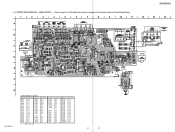
... Q786 Q901 Q902 Q903 Q904 (Q905) (Q906) Location E-7 E-7 E-8 E-7 E-7 D-9 E-8 E-8 D-6 D-6 D-5 B-8 B-9 D-9 E-8 E-2 D-2 ( ) : AEP model only STR-DE197 17 17 MAIN SECTION - • Refer to page 13 for Circuit Boards Location and page 14 for Common Note on Printed Wiring Boards. 1 2 3 4 5 6... R786 R787 JW498 C791 EP901 JW492 JW493 JW495 (Page 20) CNP801 R903 12 13 CNJ901 CNP905 T901 14 G J803 • Semiconductor Location Ref. STR-DE197 4-5. No. D701 D751 D781 D782 D783 D784 D785 D786 D787 D788 D789 D901 D902 D903 D904 D905 D906 Location D-6 D-6 E-9 C-6 C-6 D-6...
... Q786 Q901 Q902 Q903 Q904 (Q905) (Q906) Location E-7 E-7 E-8 E-7 E-7 D-9 E-8 E-8 D-6 D-6 D-5 B-8 B-9 D-9 E-8 E-2 D-2 ( ) : AEP model only STR-DE197 17 17 MAIN SECTION - • Refer to page 13 for Circuit Boards Location and page 14 for Common Note on Printed Wiring Boards. 1 2 3 4 5 6... R786 R787 JW498 C791 EP901 JW492 JW493 JW495 (Page 20) CNP801 R903 12 13 CNJ901 CNP905 T901 14 G J803 • Semiconductor Location Ref. STR-DE197 4-5. No. D701 D751 D781 D782 D783 D784 D785 D786 D787 D788 D789 D901 D902 D903 D904 D905 D906 Location D-6 D-6 E-9 C-6 C-6 D-6...

Service Manual
Page 23
...685-646-79 SCREW +BVTP 3X8 TYPE2 IT-3 Remark 23 SECTION 5 EXPLODED VIEWS • Color Indication of this parts list. • Abbreviation CND : Canadian model 5-1. Replace only with mark 0 are seldom required for routine service. Les composants identifiés par une marque 0 sont critiques pour la sécurité. ... exploded views are not supplied. • Items marked "*" are not stocked since they may have some difference from the original one. CASE SECTION 2 STR-DE197 Ver. 1.2 The components identified by mark 0 or dotted line with part number specified.
...685-646-79 SCREW +BVTP 3X8 TYPE2 IT-3 Remark 23 SECTION 5 EXPLODED VIEWS • Color Indication of this parts list. • Abbreviation CND : Canadian model 5-1. Replace only with mark 0 are seldom required for routine service. Les composants identifiés par une marque 0 sont critiques pour la sécurité. ... exploded views are not supplied. • Items marked "*" are not stocked since they may have some difference from the original one. CASE SECTION 2 STR-DE197 Ver. 1.2 The components identified by mark 0 or dotted line with part number specified.
Service Manual
Page 26
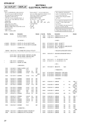
...board. Ne les remplacer que par une piéce portant le numéro spécifié. CNS4 CNS5 Part No. STR-DE197 SECTION 6 AC OUTLET DISPLAY ELECTRICAL PARTS LIST NOTE: • Due to standardization, replacements in the parts list may be anticipated when ...dotted line with part number specified. Replace only with mark 0 are in ohms. METAL:Metal-film resistor. F:nonflammable • Abbreviation CND : Canadian model • Items marked "*" are not stocked since they may have some difference from the original one. • RESISTORS All resistors are critical for...
...board. Ne les remplacer que par une piéce portant le numéro spécifié. CNS4 CNS5 Part No. STR-DE197 SECTION 6 AC OUTLET DISPLAY ELECTRICAL PARTS LIST NOTE: • Due to standardization, replacements in the parts list may be anticipated when ...dotted line with part number specified. Replace only with mark 0 are in ohms. METAL:Metal-film resistor. F:nonflammable • Abbreviation CND : Canadian model • Items marked "*" are not stocked since they may have some difference from the original one. • RESISTORS All resistors are critical for...

Service Manual
Page 33
... BOARD (COMPONENT SIDE) - Subject: Change the MAIN, DISPLAY, VOLUME, H.PHONE, POWER, FUNCTION KEY and AC OUTLET boards. DISPLAY BOARD Part No. MAIN BOARD Part No. STR-DE197 SERVICE MANUAL Ver. 1.3 2006. 09 US Model Canadian Model AEP Model SUPPLEMENT-1 File this Supplement-1.
... BOARD (COMPONENT SIDE) - Subject: Change the MAIN, DISPLAY, VOLUME, H.PHONE, POWER, FUNCTION KEY and AC OUTLET boards. DISPLAY BOARD Part No. MAIN BOARD Part No. STR-DE197 SERVICE MANUAL Ver. 1.3 2006. 09 US Model Canadian Model AEP Model SUPPLEMENT-1 File this Supplement-1.

Service Manual
Page 35
... from the component side. • f : internal component. • : Pattern from the side which enables seeing. • Abbreviation CND : Canadian model. • (( )): Page of Supplement-1. STR-DE197 • IC Block Diagram IC402 R2S15904SP INR4 LOUT ROUT AGND VCC REFIN DATA CLK DGND TRER TREL NC NC BASSL2 28 27 26...IGOUTR VOLINR BASSR1 BASSR2 BASSL1 • Waveform 1 IC201 eg (X2) 4.19 MHz 2V/DIV, 0.2µsec/DIV 3.6 Vp-p STR-DE197 3 3 C Q These are taken with part number specified. Replace only with a VOM (Input impedance 10 MΩ).
... from the component side. • f : internal component. • : Pattern from the side which enables seeing. • Abbreviation CND : Canadian model. • (( )): Page of Supplement-1. STR-DE197 • IC Block Diagram IC402 R2S15904SP INR4 LOUT ROUT AGND VCC REFIN DATA CLK DGND TRER TREL NC NC BASSL2 28 27 26...IGOUTR VOLINR BASSR1 BASSR2 BASSL1 • Waveform 1 IC201 eg (X2) 4.19 MHz 2V/DIV, 0.2µsec/DIV 3.6 Vp-p STR-DE197 3 3 C Q These are taken with part number specified. Replace only with a VOM (Input impedance 10 MΩ).

Service Manual
Page 36
... Q782 Q783 Q784 Q785 Q786 Q901 Q902 Q903 Q904 (Q905) (Q906) Location F-7 F-7 F-8 E-7 E-7 D-9 E-8 E-8 D-6 D-6 D-5 B-8 B-9 D-9 E-8 E-2 D-2 ( ) : AEP model only STR-DE197 4 4 MAIN SECTION - • Refer to page 13 of Service Manual for Circuit Boards Location. : Uses unleaded solder. 1 2 3 4 5 6 7 8 9 10 11 A J801...D911 D909 D910 D908 C791 EP901 ((Page 7)) CNP801 12 13 CNJ901 CNP905 T901 14 G J803 • Semiconductor Location Ref. STR-DE197 1. No. PRINTED WIRING BOARDS - No. IC901 IC902 IC903 IC904 (IC905) IC906 (IC907) Location C-9 D-9 C-4 C-2 E-2 E-2 ...
... Q782 Q783 Q784 Q785 Q786 Q901 Q902 Q903 Q904 (Q905) (Q906) Location F-7 F-7 F-8 E-7 E-7 D-9 E-8 E-8 D-6 D-6 D-5 B-8 B-9 D-9 E-8 E-2 D-2 ( ) : AEP model only STR-DE197 4 4 MAIN SECTION - • Refer to page 13 of Service Manual for Circuit Boards Location. : Uses unleaded solder. 1 2 3 4 5 6 7 8 9 10 11 A J801...D911 D909 D910 D908 C791 EP901 ((Page 7)) CNP801 12 13 CNJ901 CNP905 T901 14 G J803 • Semiconductor Location Ref. STR-DE197 1. No. PRINTED WIRING BOARDS - No. IC901 IC902 IC903 IC904 (IC905) IC906 (IC907) Location C-9 D-9 C-4 C-2 E-2 E-2 ...

Service Manual
Page 41
...;cifié. F:nonflammable • Abbreviation CND : Canadian model • Items marked "*" are not stocked since they may be anticipated when ordering these items. • SEMICONDUCTORS In each case, u : µ, for routine service. uPD.. : µPD.. • CAPACITORS uF : µF • COILS uH : µH STR-DE197 Ver. 1.5 AC OUTLET DISPLAY The components identified by...
...;cifié. F:nonflammable • Abbreviation CND : Canadian model • Items marked "*" are not stocked since they may be anticipated when ordering these items. • SEMICONDUCTORS In each case, u : µ, for routine service. uPD.. : µPD.. • CAPACITORS uF : µF • COILS uH : µH STR-DE197 Ver. 1.5 AC OUTLET DISPLAY The components identified by...
Service Manual
Page 49
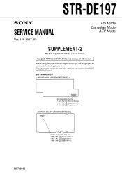
STR-DE197 SERVICE MANUAL Ver. 1.4 2007. 03 US Model Canadian Model AEP Model SUPPLEMENT-2 File this Supplement-2. DISPLAY BOARD Part No. 1-861-586-1 : Service Manual 1-871-791-1 :Supplement-1 1-861-586-2 :Supplement-2 9-877-864-82 1 When performing service and ... and schematic diagram of the MAIN and DISPLAY boards. DISPLAY BOARD (COMPONENT SIDE) - MAIN BOARD (COMPONENT SIDE) - Subject: MAIN and DISPLAY boards change of US model. DISCRIMINATION - MAIN BOARD Part No. 1-861-592-1 : Service Manual 1-871-790-1 :Supplement-1 1-861-592-2 :Supplement-2 -
STR-DE197 SERVICE MANUAL Ver. 1.4 2007. 03 US Model Canadian Model AEP Model SUPPLEMENT-2 File this Supplement-2. DISPLAY BOARD Part No. 1-861-586-1 : Service Manual 1-871-791-1 :Supplement-1 1-861-586-2 :Supplement-2 9-877-864-82 1 When performing service and ... and schematic diagram of the MAIN and DISPLAY boards. DISPLAY BOARD (COMPONENT SIDE) - MAIN BOARD (COMPONENT SIDE) - Subject: MAIN and DISPLAY boards change of US model. DISCRIMINATION - MAIN BOARD Part No. 1-861-592-1 : Service Manual 1-871-790-1 :Supplement-1 1-861-592-2 :Supplement-2 -

