VAIO User Guide
Page 60
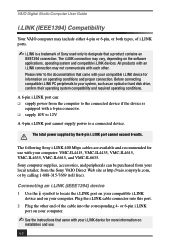
...not communicate with a 6-pin connector. ❑ supply 10V to 12V. Please refer to the documentation that came with your computer: VMC-IL4415, VMC-IL4435, VMC-IL4615, VMC-IL4635, VMC-IL6615, and VMC-IL6635. A 4-pin i.LINK port cannot supply power to your system, such as...an optical or hard disk drive, confirm their operating system compatibility and required operating conditions. Sony computer supplies, accessories, and peripherals can : ❑ supply power from the Sony VAIO Direct Web site at http://vaio.sonystyle.com, or by the 6-pin i.LINK port cannot exceed 6 watts. Before ...
...not communicate with a 6-pin connector. ❑ supply 10V to 12V. Please refer to the documentation that came with your computer: VMC-IL4415, VMC-IL4435, VMC-IL4615, VMC-IL4635, VMC-IL6615, and VMC-IL6635. A 4-pin i.LINK port cannot supply power to your system, such as...an optical or hard disk drive, confirm their operating system compatibility and required operating conditions. Sony computer supplies, accessories, and peripherals can : ❑ supply power from the Sony VAIO Direct Web site at http://vaio.sonystyle.com, or by the 6-pin i.LINK port cannot exceed 6 watts. Before ...

System Reference Manual
Page 11
... Avis de l'Industrie Canada ix Chapter 1 - Identifying Components 1 Front View...2 Drives ...3 Buttons and Switches 4 Indicators 5 Connectors 6 Rear View ...7 Icon Labels 8 I/O Connectors 10 Expansion Slots 14 Chapter 2 - Configuring Your System 15 Accessing the BIOS Setup Utility 16 Changing Power Management Settings 17 xi vii Telephone Consumer Guidelines (Canada vii Disposal of 1991 (United States) ....
... Avis de l'Industrie Canada ix Chapter 1 - Identifying Components 1 Front View...2 Drives ...3 Buttons and Switches 4 Indicators 5 Connectors 6 Rear View ...7 Icon Labels 8 I/O Connectors 10 Expansion Slots 14 Chapter 2 - Configuring Your System 15 Accessing the BIOS Setup Utility 16 Changing Power Management Settings 17 xi vii Telephone Consumer Guidelines (Canada vii Disposal of 1991 (United States) ....

System Reference Manual
Page 20
.... A 6-pin i.LINK connector can supply power from the computer to an audio cable (supplied). Connects to the device if the device also has a 6-pin i.LINK port. A 4-pin i.LINK connector cannot supply power to a video cable (supplied...). Connects to the device. Connects to USB devices. * To connect to an audio cable (supplied). 6 VAIO Digital Studio System Reference Manual Connectors...
.... A 6-pin i.LINK connector can supply power from the computer to an audio cable (supplied). Connects to the device if the device also has a 6-pin i.LINK port. A 4-pin i.LINK connector cannot supply power to a video cable (supplied...). Connects to the device. Connects to USB devices. * To connect to an audio cable (supplied). 6 VAIO Digital Studio System Reference Manual Connectors...
System Reference Manual
Page 50
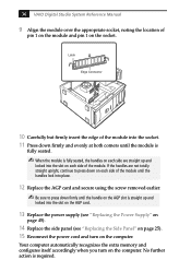
... module is required. 36 VAIO Digital Studio System Reference Manual 9 Align the module over the appropriate socket, noting the location of pin 1 on the module and pin 1 on the computer. Latch Edge Connector 10 Carefully but firmly insert...module until the handles lock into the slot on the AGP card. 13 Replace the power supply (see "Replacing the Power Supply" on page 45). 14 Replace the side panel (see "Replacing the Side Panel"... on page 25). 15 Reconnect the power cord and turn on the socket. If the handles are straight up and locked into ...
... module is required. 36 VAIO Digital Studio System Reference Manual 9 Align the module over the appropriate socket, noting the location of pin 1 on the module and pin 1 on the computer. Latch Edge Connector 10 Carefully but firmly insert...module until the handles lock into the slot on the AGP card. 13 Replace the power supply (see "Replacing the Power Supply" on page 45). 14 Replace the side panel (see "Replacing the Side Panel"... on page 25). 15 Reconnect the power cord and turn on the socket. If the handles are straight up and locked into ...
System Reference Manual
Page 53
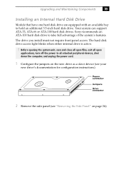
... the computer, and unplug the power cord. 1 Configure the jumpers on page 24). Your system can support ATA-33, ATA-66 or ATA-100 hard disk drives. Sony recommends an ATA-100 hard disk drive to all open applications, turn off the power to take full advantage of the system's features. Power connector Jumpers Drive connector 2 Remove...
... the computer, and unplug the power cord. 1 Configure the jumpers on page 24). Your system can support ATA-33, ATA-66 or ATA-100 hard disk drives. Sony recommends an ATA-100 hard disk drive to all open applications, turn off the power to take full advantage of the system's features. Power connector Jumpers Drive connector 2 Remove...
System Reference Manual
Page 54
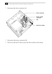
A B C Drive connector Power supply connector Tab Disk drive holder 4 Disconnect the power connector (B). 5 Pull out on the tab (C) that secures the drive holder to the chassis. 40 VAIO Digital Studio System Reference Manual 3 Disconnect the drive connector (A).
A B C Drive connector Power supply connector Tab Disk drive holder 4 Disconnect the power connector (B). 5 Pull out on the tab (C) that secures the drive holder to the chassis. 40 VAIO Digital Studio System Reference Manual 3 Disconnect the drive connector (A).
System Reference Manual
Page 56
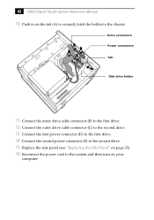
C E B D A Drive connectors Power connectors Tab Disk drive holder 11 Connect the inner drive cable connector (B) to the first drive. 12 Connect the outer drive cable connector (C) to the second drive. 13 Connect the first power connector (D) to the first drive. 14 Connect the second power connector (E) to the second drive. 15 Replace the side panel (see "Replacing the Side Panel" on your computer. 42 VAIO Digital Studio System Reference Manual 10 Push in on the tab (A) to securely latch the holder to the system and then turn on page 25). 16 Reconnect the power cord to the chassis.
C E B D A Drive connectors Power connectors Tab Disk drive holder 11 Connect the inner drive cable connector (B) to the first drive. 12 Connect the outer drive cable connector (C) to the second drive. 13 Connect the first power connector (D) to the first drive. 14 Connect the second power connector (E) to the second drive. 15 Replace the side panel (see "Replacing the Side Panel" on your computer. 42 VAIO Digital Studio System Reference Manual 10 Push in on the tab (A) to securely latch the holder to the system and then turn on page 25). 16 Reconnect the power cord to the chassis.
System Reference Manual
Page 61
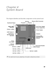
Chapter 4 System Board This chapter identifies and describes components on the system configuration purchased. 47 Keyboard, Mouse CPU Fan Memory Stick Connector Processor Memory USB3, USB4 Ethernet Printer, i.LINK 1394 Header 3 Serial Port, Mic In, Line In Line Out CD-In (not used) Aux-In ...(not used) Slot No. 1 (CNR) Slot No. 2 (PCI) Slot No. 3 (PCI) Slot No. 4 (PCI) Aux Power Supply Power Supply Fan Power Supply Diskette Primary IDE Secondary IDE Battery CMOS Clear Front Panel Header USB23 Header Slot No. 5 (AGP) ✍ Your system board may vary, depending...
Chapter 4 System Board This chapter identifies and describes components on the system configuration purchased. 47 Keyboard, Mouse CPU Fan Memory Stick Connector Processor Memory USB3, USB4 Ethernet Printer, i.LINK 1394 Header 3 Serial Port, Mic In, Line In Line Out CD-In (not used) Aux-In ...(not used) Slot No. 1 (CNR) Slot No. 2 (PCI) Slot No. 3 (PCI) Slot No. 4 (PCI) Aux Power Supply Power Supply Fan Power Supply Diskette Primary IDE Secondary IDE Battery CMOS Clear Front Panel Header USB23 Header Slot No. 5 (AGP) ✍ Your system board may vary, depending...
System Reference Manual
Page 93
See Also BIOS CMOS Setup Utility 16 codes, beeps 65 communications, specifications 75 computer lithium battery viii configuring power management 17 connectors i.LINK 6 monitor 11 power 49 USB 6 cover, slot 37 covering I/O slot 38 CPU - See Also slots F fax/modem - See ... 76 79 See modem card floppy disk drive specifications 76 front view 2 buttons and switches 4 connectors 5, 6 indicators 5 G Giga Pocket specifications 75 graphics controller - See processor D display, power management 17 disposal of lithium battery viii DMA channel assignments 68 drive installing additional drive 39 E...
See Also BIOS CMOS Setup Utility 16 codes, beeps 65 communications, specifications 75 computer lithium battery viii configuring power management 17 connectors i.LINK 6 monitor 11 power 49 USB 6 cover, slot 37 covering I/O slot 38 CPU - See Also slots F fax/modem - See ... 76 79 See modem card floppy disk drive specifications 76 front view 2 buttons and switches 4 connectors 5, 6 indicators 5 G Giga Pocket specifications 75 graphics controller - See processor D display, power management 17 disposal of lithium battery viii DMA channel assignments 68 drive installing additional drive 39 E...
System Reference Manual
Page 94
... 64 PCI add-in card installing 28 removing 26 PCI bus specifications 74 power connector 49 power management, configuring 17 processor specifications 73, 74 R RAM - See processor modem - See graphics RIMM - 80 VAIO Digital Studio System Reference Manual I i.LINK connector 6 I/O address map 69 I/O connectors i.LINK 13 keyboard and mouse 10 mic, line in, headphones 12 monitor...
... 64 PCI add-in card installing 28 removing 26 PCI bus specifications 74 power connector 49 power management, configuring 17 processor specifications 73, 74 R RAM - See processor modem - See graphics RIMM - 80 VAIO Digital Studio System Reference Manual I i.LINK connector 6 I/O address map 69 I/O connectors i.LINK 13 keyboard and mouse 10 mic, line in, headphones 12 monitor...
Marketing Specifications
Page 1
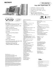
PCV-RX755 Sony VAIO® Digital Studio™ PC * Display sold separately. Information Technology Product Division 16765 West Bernardo Drive, San Diego, CA 92127 For more information: 1.800.4SONYPC (476-6972) Web address: http://www.sony.com/vaio Computer Interface: The computer industry lacks standards, and therefore, there are a multitude of Microsoft Corporation. While Sony representatives or Sony authorized dealers may...
PCV-RX755 Sony VAIO® Digital Studio™ PC * Display sold separately. Information Technology Product Division 16765 West Bernardo Drive, San Diego, CA 92127 For more information: 1.800.4SONYPC (476-6972) Web address: http://www.sony.com/vaio Computer Interface: The computer industry lacks standards, and therefore, there are a multitude of Microsoft Corporation. While Sony representatives or Sony authorized dealers may...

