

Warranty Card
Page 1
... obtain warranty service. ACCESSORIES: Parts and labor for removal and installation is determined to be presented to any part of the Product, including the antenna. This warranty does not cover customer instruction, installation, set forth as fuses or batteries). After 90 days from Sony authorized service facilities or a Sony Service Center at no charge, new or rebuilt replacements in exchange for defective parts for one (1) year (color picture tube...
... obtain warranty service. ACCESSORIES: Parts and labor for removal and installation is determined to be presented to any part of the Product, including the antenna. This warranty does not cover customer instruction, installation, set forth as fuses or batteries). After 90 days from Sony authorized service facilities or a Sony Service Center at no charge, new or rebuilt replacements in exchange for defective parts for one (1) year (color picture tube...

Child Safety: It Makes A Difference Where Your TV Stands
Page 1
... your TV (and other electronic components). Use appropriate angle braces, straps and anchors to climb on dressers, bookcases, shelves, desks, audio speakers, chests or carts. Thank you have more than one television. The home theater entertainment experience is committed to the wall (but never screw directly into the TV). As a result TV sets may stimulate a child's curiosity. THIS...
... your TV (and other electronic components). Use appropriate angle braces, straps and anchors to climb on dressers, bookcases, shelves, desks, audio speakers, chests or carts. Thank you have more than one television. The home theater entertainment experience is committed to the wall (but never screw directly into the TV). As a result TV sets may stimulate a child's curiosity. THIS...
Primary User Manual
Page 1
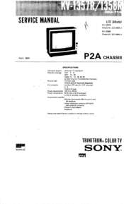
... channels) Picture tube Trinitron tube 13-inch picture measured diagonally Hit connector Auxiliary RF input for VHF channels 2 - 6 75-ohm (F-type) Power requirements 120 V ac, 60 Hz Power consumption 90 W (max.), 58 W (average) 2.2 W (in standby condition) Accessories supplied Remote Commander RM-714 with 2 size AA batteries Indoor telescopic antenna (VHF/UHF) with antenna connector Phono-F plug adaptor Earphone Design and specifications subject to change without notice. SERVIC€ MANUAL US Model KV...
... channels) Picture tube Trinitron tube 13-inch picture measured diagonally Hit connector Auxiliary RF input for VHF channels 2 - 6 75-ohm (F-type) Power requirements 120 V ac, 60 Hz Power consumption 90 W (max.), 58 W (average) 2.2 W (in standby condition) Accessories supplied Remote Commander RM-714 with 2 size AA batteries Indoor telescopic antenna (VHF/UHF) with antenna connector Phono-F plug adaptor Earphone Design and specifications subject to change without notice. SERVIC€ MANUAL US Model KV...
Primary User Manual
Page 2
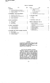
... 52 WARNING!! SAFETY-RELATED COMPONENT WARNING!! REPLACED OR IMPROPER OPERATION IS SUSPECTED. Location and Function of Back Cover 2-2. Installation of Controls 1-2. Function of the Remote Commander 4. Operation of Buttons on the Remote Commander 3. SSIBLE SHOCK THE CHASSIS OF THIS RECEIVER IS DIRECTLY CON- CIRCUIT ADJUSTMENTS THAT ARE CRITICAL TO SAFE OPERATION ARE IDENTIFIED IN THIS MANUAL. GENERAL 1-1. SETUP ADJUSTMENTS 3-1. Battery Installation 2. Normal TV Operation (Panel Operation) 1-3. A Board Removal (for Checking It...
... 52 WARNING!! SAFETY-RELATED COMPONENT WARNING!! REPLACED OR IMPROPER OPERATION IS SUSPECTED. Location and Function of Back Cover 2-2. Installation of Controls 1-2. Function of the Remote Commander 4. Operation of Buttons on the Remote Commander 3. SSIBLE SHOCK THE CHASSIS OF THIS RECEIVER IS DIRECTLY CON- CIRCUIT ADJUSTMENTS THAT ARE CRITICAL TO SAFE OPERATION ARE IDENTIFIED IN THIS MANUAL. GENERAL 1-1. SETUP ADJUSTMENTS 3-1. Battery Installation 2. Normal TV Operation (Panel Operation) 1-3. A Board Removal (for Checking It...
Primary User Manual
Page 3
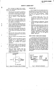
... 0.5 mA (500 microampers). Measuring the voltage drop across a resistor by any ). KV-1357R/1358R RM-714 SAFETY CHECK-OUT After correcting the original service problem, perform the following safety checks before releasing the set to the customer and recommend their replacement. 6. Check the antenna terminals, metal trim, "metallized" knobs, screws, and all battery operated digital multimeters that were installed during a previous repair.
... 0.5 mA (500 microampers). Measuring the voltage drop across a resistor by any ). KV-1357R/1358R RM-714 SAFETY CHECK-OUT After correcting the original service problem, perform the following safety checks before releasing the set to the customer and recommend their replacement. 6. Check the antenna terminals, metal trim, "metallized" knobs, screws, and all battery operated digital multimeters that were installed during a previous repair.
Primary User Manual
Page 4
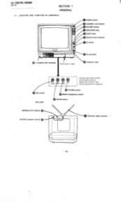
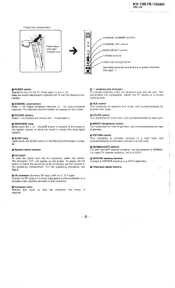
CV-1357R/1358R IM-714 SECTION 1 GENERAL 1-1. Hit connector Connector cover HUE control Rear panel NORMAUCATV selector 15 VHF/UHF antenna terminal Normally set these controls at the center position. Adjust the controls if any picture adjustment is required. 14 PICTURE control BRIGHT (brightness) control COLOR control Telescopic dipole antenna -4- LOCATION AND FUNCTION OF CONTROLS POWER switch CHANNEL scan buttons VOLUME buttons RESPONSE lamp SLEEP lamp Remote control detector Hit button ,1)earphone jack (minijack) Push down to open.
CV-1357R/1358R IM-714 SECTION 1 GENERAL 1-1. Hit connector Connector cover HUE control Rear panel NORMAUCATV selector 15 VHF/UHF antenna terminal Normally set these controls at the center position. Adjust the controls if any picture adjustment is required. 14 PICTURE control BRIGHT (brightness) control COLOR control Telescopic dipole antenna -4- LOCATION AND FUNCTION OF CONTROLS POWER switch CHANNEL scan buttons VOLUME buttons RESPONSE lamp SLEEP lamp Remote control detector Hit button ,1)earphone jack (minijack) Push down to open.
Primary User Manual
Page 5
...RF input, VHF ch. 2 - 6, F-type) Connect an RF output of a home video game, a microcomputer, or a portable video cassette recorder to CATV. Connector cover Remove this button. This disconnects the loudspeaker. COLOR control Turn clockwise for more brightness, and counterclockwise for less brightness. J Telescopic dipole antenna CHANNEL NUMBER buttons O CHANNEL SET switch BAND SELECT switch TUNING buttons FINE (fine tuning) button Use these switches and buttons to be connected, use the controls in the presetting compartment. CHANNEL scan buttons Press + for lower-numbered channels...
...RF input, VHF ch. 2 - 6, F-type) Connect an RF output of a home video game, a microcomputer, or a portable video cassette recorder to CATV. Connector cover Remove this button. This disconnects the loudspeaker. COLOR control Turn clockwise for more brightness, and counterclockwise for less brightness. J Telescopic dipole antenna CHANNEL NUMBER buttons O CHANNEL SET switch BAND SELECT switch TUNING buttons FINE (fine tuning) button Use these switches and buttons to be connected, use the controls in the presetting compartment. CHANNEL scan buttons Press + for lower-numbered channels...

Primary User Manual
Page 6
... seconds. a 0 .s. CHANNEL. NORMAL TV OPERATION (PANEL OPERATION) 6- 1Depress POWER. To extinguish the channel number, press CHANNEL DISPLAY on the screen will appear. 4- 3 Adjust the volume by pressing + or - to your preference using the HUE, sit COLOR, BRIGHT and PICTURE controls. Tills indication will be longer. A Adjust the picture to change the channel, the indication on the Remote Commander. For presetting desired channels, see pages 7 - 9. The picture will disappear after the adjustment is completed. VOLUME. 2 Select...
... seconds. a 0 .s. CHANNEL. NORMAL TV OPERATION (PANEL OPERATION) 6- 1Depress POWER. To extinguish the channel number, press CHANNEL DISPLAY on the screen will appear. 4- 3 Adjust the volume by pressing + or - to your preference using the HUE, sit COLOR, BRIGHT and PICTURE controls. Tills indication will be longer. A Adjust the picture to change the channel, the indication on the Remote Commander. For presetting desired channels, see pages 7 - 9. The picture will disappear after the adjustment is completed. VOLUME. 2 Select...
Primary User Manual
Page 7
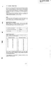
... television broadcast channels or to receive signals from the video cassette recorder. To set can be active in "PRESETTING PROCEDURE" on the available channels. * The designation of the VHF channels 2 -13, UHF channels 14 - 69, and the 25 cable TV channels listed below. but use letters or numbers to receive any of the VHF channels 2 - 6 according to the type of your set is factory-adjusted to this chart. BEFORE SETTING CHANNELS Before setting...
... television broadcast channels or to receive signals from the video cassette recorder. To set can be active in "PRESETTING PROCEDURE" on the available channels. * The designation of the VHF channels 2 -13, UHF channels 14 - 69, and the 25 cable TV channels listed below. but use letters or numbers to receive any of the VHF channels 2 - 6 according to the type of your set is factory-adjusted to this chart. BEFORE SETTING CHANNELS Before setting...

Primary User Manual
Page 8
... RESPONSE lamp lights steadily when the highest- or the lowest-numbered channel within the selected band. . . _ Lower-numbered channels - CHANNEL scan buttons 1_ Depress POWER. 2 Set CHANNEL SET to be selected regardless of the presently set BAND SELECT to either of the desired station is ... - If the picture turns black or.into snow, set channel. If the number cannot be underlined. ' 5 Keep + or - UNM ---- 1 ; Hit button Turn on the equipment connected to...
... RESPONSE lamp lights steadily when the highest- or the lowest-numbered channel within the selected band. . . _ Lower-numbered channels - CHANNEL scan buttons 1_ Depress POWER. 2 Set CHANNEL SET to be selected regardless of the presently set BAND SELECT to either of the desired station is ... - If the picture turns black or.into snow, set channel. If the number cannot be underlined. ' 5 Keep + or - UNM ---- 1 ; Hit button Turn on the equipment connected to...


