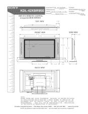
Dimensions Diagrams
Page 1
... IN THE DESIGN OR MANUFACTURE OF ENCLOSURES . Consumer Integrated Systems • Park Ridge, New Jersey 07656 • FAX (201) 930 7891 • www.sony.com/dn Features and specifications subject to change without notice. • Non-metric weights and measurements are approximate. KDL-42XBR950 RMY-914 REMOTE CONTROL w/supplied MDB-XBR950 MDDEEOSSDCCERRLII:PPTTIIOONN...
... IN THE DESIGN OR MANUFACTURE OF ENCLOSURES . Consumer Integrated Systems • Park Ridge, New Jersey 07656 • FAX (201) 930 7891 • www.sony.com/dn Features and specifications subject to change without notice. • Non-metric weights and measurements are approximate. KDL-42XBR950 RMY-914 REMOTE CONTROL w/supplied MDB-XBR950 MDDEEOSSDCCERRLII:PPTTIIOONN...

Operating Instructions
Page 3
... days, disconnect the power by the Limited Warranty. 1 Use of this Plasma Display Panel may cause harmful interference with an extension cord, receptacle or other than 750hPa), this television receiver for long periods of the general public may require authorization from that may ...reasonable protection against harmful interference in the literature accompanying the appliance. These limits are unable to fit into the outlet, contact your Sony dealer regarding this equipment. This equipment generates, uses, and can be using TV games, computers, and similar products with the...
... days, disconnect the power by the Limited Warranty. 1 Use of this Plasma Display Panel may cause harmful interference with an extension cord, receptacle or other than 750hPa), this television receiver for long periods of the general public may require authorization from that may ...reasonable protection against harmful interference in the literature accompanying the appliance. These limits are unable to fit into the outlet, contact your Sony dealer regarding this equipment. This equipment generates, uses, and can be using TV games, computers, and similar products with the...

Operating Instructions
Page 7
... and cause fire or damage the unit. s Never cover the slots and openings with a cloth or other similar surface. Place the Media receiver unit on a stable level surface so as follows: Air circulation is blocked. Ensure reliable operation of the unit by placing the set to .... When installing the unit on a bed, sofa, rug or other materials. Media receiver unit: Top view Never place the Media receiver unit in ) TV VIDEO MEMORY STICK i.LINK PIC OFF i.LINK INPUT SELECT - Use an optional Sony stand, which has adequate strength. VOL + - If the unit is provided, the...
... and cause fire or damage the unit. s Never cover the slots and openings with a cloth or other similar surface. Place the Media receiver unit on a stable level surface so as follows: Air circulation is blocked. Ensure reliable operation of the unit by placing the set to .... When installing the unit on a bed, sofa, rug or other materials. Media receiver unit: Top view Never place the Media receiver unit in ) TV VIDEO MEMORY STICK i.LINK PIC OFF i.LINK INPUT SELECT - Use an optional Sony stand, which has adequate strength. VOL + - If the unit is provided, the...
Operating Instructions
Page 8
Do not move the set with such power lines or circuits. The unit may result in damage and will prevent damage to the receiver due to an antenna discharge unit, size of grounding conductors, location of other controls may fall and be caused. WHEN INSTALLING AN OUTDOOR ...unused for long periods of overhead power lines or other than that are specified in the operating instructions. Ship and vessel Do not install this television receiver during a lightning storm, or when it can come in contact with the AC power cord plugged in. Antenna Grounding According to the National ...
Do not move the set with such power lines or circuits. The unit may result in damage and will prevent damage to the receiver due to an antenna discharge unit, size of grounding conductors, location of other controls may fall and be caused. WHEN INSTALLING AN OUTDOOR ...unused for long periods of overhead power lines or other than that are specified in the operating instructions. Ship and vessel Do not install this television receiver during a lightning storm, or when it can come in contact with the AC power cord plugged in. Antenna Grounding According to the National ...

Operating Instructions
Page 9
...unused for your footing while installing the TV. It may damage the unit. Cable wiring Take care not to catch your feet on the Media receiver unit. The wide blade or the third prong are required, be sure the service technician certifies in electric shock or damage the unit. Safety ...you carry the TV in the specified manner Carrying the TV requires at the unit. s As the glass surface of persons, it on the Media receiver unit. It may damage the unit. Otherwise electric shock may cause electric shock or damage to follow the instructions given below. Object placement Do not...
...unused for your footing while installing the TV. It may damage the unit. Cable wiring Take care not to catch your feet on the Media receiver unit. The wide blade or the third prong are required, be sure the service technician certifies in electric shock or damage the unit. Safety ...you carry the TV in the specified manner Carrying the TV requires at the unit. s As the glass surface of persons, it on the Media receiver unit. It may damage the unit. Otherwise electric shock may cause electric shock or damage to follow the instructions given below. Object placement Do not...
Operating Instructions
Page 11
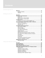
... Welcome 13 Package Contents 13 Features 13 Setting Up the TV Overview 17 TV Controls and Connectors 18 Display unit 18 Media receiver unit Front Panel 20 Media receiver unit Rear Panel 22 Installing the TV 23 Detaching the speakers (KDE61XBR950 only 25 Basic Connections: Connecting a Cable or Antenna ...Optional Equipment 30 About Using S VIDEO 30 VCR and Cable 31 VCR and Cable Box 33 Two VCRs for Tape Editing 35 Satellite Receiver 37 Satellite Receiver and VCR 39 DVD Player with Component Video Connectors 41 DVD Player with S VIDEO and Audio Connectors 43 Camcorder 44 Audio...
... Welcome 13 Package Contents 13 Features 13 Setting Up the TV Overview 17 TV Controls and Connectors 18 Display unit 18 Media receiver unit Front Panel 20 Media receiver unit Rear Panel 22 Installing the TV 23 Detaching the speakers (KDE61XBR950 only 25 Basic Connections: Connecting a Cable or Antenna ...Optional Equipment 30 About Using S VIDEO 30 VCR and Cable 31 VCR and Cable Box 33 Two VCRs for Tape Editing 35 Satellite Receiver 37 Satellite Receiver and VCR 39 DVD Player with Component Video Connectors 41 DVD Player with S VIDEO and Audio Connectors 43 Camcorder 44 Audio...
Operating Instructions
Page 15
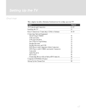
...: s Flat panel display unit (PDM-6110, PDM-5010 or PDM-4210) s Media receiver unit (MBD-XBR950) s Remote control (RM-Y1000) and two size AA batteries s Two...you start to connect your new TV include: s Integrated HDTV: You can watch digital television programs and enjoy the improved audio/video quality offered...WEGA Engine™: Delivers superb picture quality from any video source by minimizing the signal deterioration caused by these on hand before you may need to set up and operate the TV in its basic configuration. Introducing the TV Welcome Thank you for purchasing the Sony...
...: s Flat panel display unit (PDM-6110, PDM-5010 or PDM-4210) s Media receiver unit (MBD-XBR950) s Remote control (RM-Y1000) and two size AA batteries s Two...you start to connect your new TV include: s Integrated HDTV: You can watch digital television programs and enjoy the improved audio/video quality offered...WEGA Engine™: Delivers superb picture quality from any video source by minimizing the signal deterioration caused by these on hand before you may need to set up and operate the TV in its basic configuration. Introducing the TV Welcome Thank you for purchasing the Sony...
Operating Instructions
Page 19
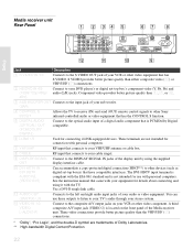
... your TV. Setting Up the TV Overview This chapter includes illustrated instructions for Tape Editing Satellite Receiver Satellite Receiver and VCR DVD Player with Component Video Connectors DVD Player with S VIDEO and Audio Connectors Camcorder Audio Receiver Sub woofer Connecting Device with an Optical IN Connector Using the CONTROL S Feature Setting Up the...
... your TV. Setting Up the TV Overview This chapter includes illustrated instructions for Tape Editing Satellite Receiver Satellite Receiver and VCR DVD Player with Component Video Connectors DVD Player with S VIDEO and Audio Connectors Camcorder Audio Receiver Sub woofer Connecting Device with an Optical IN Connector Using the CONTROL S Feature Setting Up the...

Operating Instructions
Page 20
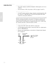
...not function on the KDE61XBR950 are detachable. terminal (KDE61XBR950 only) 18 When in standby mode, the LED lights up in red. For details, see "Contacting Sony" on page 115). 3 TIMER LED When lit, indicates one of the timers is turned off . For details, see "Detaching the speakers" on . For... details, see page 65. 5 Infrared Receiver (IR) Receives IR signals from the TV's remote control. 6 EXT SP The switch does not function on this LED will remain lit even if the TV set...
...not function on the KDE61XBR950 are detachable. terminal (KDE61XBR950 only) 18 When in standby mode, the LED lights up in red. For details, see "Contacting Sony" on page 115). 3 TIMER LED When lit, indicates one of the timers is turned off . For details, see "Detaching the speakers" on . For... details, see page 65. 5 Infrared Receiver (IR) Receives IR signals from the TV's remote control. 6 EXT SP The switch does not function on this LED will remain lit even if the TV set...

Operating Instructions
Page 21
Item 8 DISPLAY SIGNAL IN 9 AC IN Description Connect to the DISPLAY SIGNAL OUT jacks of the rear of the media receiver unit by using the supplied display interface cable. Setup 19 Connects the supplied AC power cord.
Item 8 DISPLAY SIGNAL IN 9 AC IN Description Connect to the DISPLAY SIGNAL OUT jacks of the rear of the media receiver unit by using the supplied display interface cable. Setup 19 Connects the supplied AC power cord.

Operating Instructions
Page 22
... turn off . CHANNEL + MENU ENTER qj qh qg qf qd qsqa0 Item Description 1 Main POWER Press to the TV's video inputs. 8 - For details, see "Contacting Sony" on -screen menu item. qd V v B b Press to have the TV screen turn on and off . For STANDBY LED details, see "Inserting and slot Removing a...When lit, indicates that the Memory Stick is turned off the main power of the timers is set is turned off . VOL + - Setup Media receiver unit Front Panel 1 234 56 7 8 9 POWER POWER/STANDBY TIMER i.LINK/STANDBY TV VIDEO MEMORY STICK i.LINK VIDEO 2 IN S VIDEO VIDEO L -
... turn off . CHANNEL + MENU ENTER qj qh qg qf qd qsqa0 Item Description 1 Main POWER Press to the TV's video inputs. 8 - For details, see "Contacting Sony" on -screen menu item. qd V v B b Press to have the TV screen turn on and off . For STANDBY LED details, see "Inserting and slot Removing a...When lit, indicates that the Memory Stick is turned off the main power of the timers is set is turned off . VOL + - Setup Media receiver unit Front Panel 1 234 56 7 8 9 POWER POWER/STANDBY TIMER i.LINK/STANDBY TV VIDEO MEMORY STICK i.LINK VIDEO 2 IN S VIDEO VIDEO L -
Operating Instructions
Page 24
...a copy-protected digital connection (HDCP**) to your sub woofer. (VAR) 4 CONTROL S IN/OUT Allows the TV to receive (IN) and send (OUT) remote control signals to other Sony infrared-controlled audio or video equipment that has the CONTROL S function. 5 DIGITAL AUDIO (OPTICAL) OUT (PCM/DOLBY* DIGITAL...) Connect to the optical audio input of the Media receiver unit. qs VIDEO IN 1/3 VIDEO/ L-AUDIO-R Connect to...
...a copy-protected digital connection (HDCP**) to your sub woofer. (VAR) 4 CONTROL S IN/OUT Allows the TV to receive (IN) and send (OUT) remote control signals to other Sony infrared-controlled audio or video equipment that has the CONTROL S function. 5 DIGITAL AUDIO (OPTICAL) OUT (PCM/DOLBY* DIGITAL...) Connect to the optical audio input of the Media receiver unit. qs VIDEO IN 1/3 VIDEO/ L-AUDIO-R Connect to...

Operating Instructions
Page 26
...screw slowly until you pull the cable by catching your stand or rack unit. 4 Connect the other end of display interface cable to the Media receiver unit's DISPLAY SIGNAL OUT jacks, and connect the AC power cord (supplied) to wall outlets until the screw is stabilized. When connecting optional components,... do not connect the AC power cords to the media receiver unit's AC IN jack. Do not use the supplied AC power cords. AUDIO - Do not tighten the screws too much. Be sure to ...
...screw slowly until you pull the cable by catching your stand or rack unit. 4 Connect the other end of display interface cable to the Media receiver unit's DISPLAY SIGNAL OUT jacks, and connect the AC power cord (supplied) to wall outlets until the screw is stabilized. When connecting optional components,... do not connect the AC power cords to the media receiver unit's AC IN jack. Do not use the supplied AC power cords. AUDIO - Do not tighten the screws too much. Be sure to ...

Operating Instructions
Page 28
... and forth between the cable and antenna Do This ... Setup Basic Connections: Connecting a Cable or Antenna The way in which you will connect your home receives a signal (cable, cable box, antenna) and whether or not you plan to connect a VCR. Cable Type VHF Only or combined VHF/UHF Connect As Shown...
... and forth between the cable and antenna Do This ... Setup Basic Connections: Connecting a Cable or Antenna The way in which you will connect your home receives a signal (cable, cable box, antenna) and whether or not you plan to connect a VCR. Cable Type VHF Only or combined VHF/UHF Connect As Shown...

Operating Instructions
Page 29
... TV channels Switch the TV's input between the TV's VHF/UHF (scrambled channels) and CABLE (unscrambled) inputs. Do not leave the display indication of Media receiver unit About Using This Connection with Dual Picture (Twin View, etc.) Features With this connection, you can : s Use the TV remote control to change channels...
... TV channels Switch the TV's input between the TV's VHF/UHF (scrambled channels) and CABLE (unscrambled) inputs. Do not leave the display indication of Media receiver unit About Using This Connection with Dual Picture (Twin View, etc.) Features With this connection, you can : s Use the TV remote control to change channels...
Operating Instructions
Page 30
... TV's VHF/UHF jack. 3 Run the Auto Setup program, as described in "Setting Up the Channel List" on page 27 instead. If some of Media receiver unit VHF/UHF IN OUT Cable box 28
... TV's VHF/UHF jack. 3 Run the Auto Setup program, as described in "Setting Up the Channel List" on page 27 instead. If some of Media receiver unit VHF/UHF IN OUT Cable box 28

Operating Instructions
Page 32
...for improved picture quality (compared to connect audio cables for Tape Editing Satellite Receiver Satellite Receiver and VCR DVD Player with Component Video Connectors DVD Player with S VIDEO and Audio Connectors Camcorder Audio Receiver Sub Woofer Device with S VIDEO Rear of an S VIDEO Connection S VIDEO...If the optional equipment you are connecting has an S VIDEO jack (shown at left), you also need to an A/V cable). Example of Media receiver unit S VIDEO VIDEO L AUDIO R 1 Y R P Audio cable 30 Setup Connecting Optional Equipment Use the directions in this section to connect ...
...for improved picture quality (compared to connect audio cables for Tape Editing Satellite Receiver Satellite Receiver and VCR DVD Player with Component Video Connectors DVD Player with S VIDEO and Audio Connectors Camcorder Audio Receiver Sub Woofer Device with S VIDEO Rear of an S VIDEO Connection S VIDEO...If the optional equipment you are connecting has an S VIDEO jack (shown at left), you also need to an A/V cable). Example of Media receiver unit S VIDEO VIDEO L AUDIO R 1 Y R P Audio cable 30 Setup Connecting Optional Equipment Use the directions in this section to connect ...
Operating Instructions
Page 33
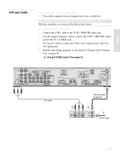
... jack to the TV's CABLE jack. 3 Use an A/V cable to connect the VCR's A/V output jacks to use all the dual picture features. Rear of Media receiver unit S VIDEO VIDEO L AUDIO R 1 VIDEO IN HD/DVD IN SUB WOOFER (1080i/720p/480p/480i) OUT(VAR) Y 4Y 5 AUDIO AUDIO PB L PB L CONTROL S L IN PR...
... jack to the TV's CABLE jack. 3 Use an A/V cable to connect the VCR's A/V output jacks to use all the dual picture features. Rear of Media receiver unit S VIDEO VIDEO L AUDIO R 1 VIDEO IN HD/DVD IN SUB WOOFER (1080i/720p/480p/480i) OUT(VAR) Y 4Y 5 AUDIO AUDIO PB L PB L CONTROL S L IN PR...

Operating Instructions
Page 36
... box to select the VCR input (VIDEO 1 in the illustration). Press TV/VIDEO repeatedly to change channels. Do not leave the display indication of Media receiver unit S VIDEO VIDEO L AUDIO R 1 VIDEO IN HD/DVD IN SUB WOOFER (1080i/720p/480p/480i) OUT(VAR) Y 4Y 5 AUDIO AUDIO PB L PB L ...cable Splitter (not supplied) Cable box Coaxial cable (not supplied) Coaxial cable (not supplied) CATV cable Notes on page 55. If you have a non-Sony VCR, you must program the remote control. See "Operating a Cable Box" on page 56 and "Operating a VCR or D-VHS" on Using This Connection ...
... box to select the VCR input (VIDEO 1 in the illustration). Press TV/VIDEO repeatedly to change channels. Do not leave the display indication of Media receiver unit S VIDEO VIDEO L AUDIO R 1 VIDEO IN HD/DVD IN SUB WOOFER (1080i/720p/480p/480i) OUT(VAR) Y 4Y 5 AUDIO AUDIO PB L PB L ...cable Splitter (not supplied) Cable box Coaxial cable (not supplied) Coaxial cable (not supplied) CATV cable Notes on page 55. If you have a non-Sony VCR, you must program the remote control. See "Operating a Cable Box" on page 56 and "Operating a VCR or D-VHS" on Using This Connection ...
Operating Instructions
Page 37
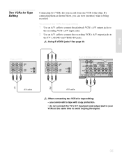
... with copy protection. - By connecting them as shown below, you can view (monitor) what is being recorded. Playback VCR A/V cable Recording VCR Rear of Media receiver unit S VIDEO VIDEO L AUDIO R 1 VIDEO IN HD/DVD IN SUB WOO (1080i/720p/480p/480i) OUT(VAR Y 4Y 5 AUDIO AUDIO PB L PB L L PR R 3 PR R R AUDIO...
... with copy protection. - By connecting them as shown below, you can view (monitor) what is being recorded. Playback VCR A/V cable Recording VCR Rear of Media receiver unit S VIDEO VIDEO L AUDIO R 1 VIDEO IN HD/DVD IN SUB WOO (1080i/720p/480p/480i) OUT(VAR Y 4Y 5 AUDIO AUDIO PB L PB L L PR R 3 PR R R AUDIO...


