
Service Manual
Page 1
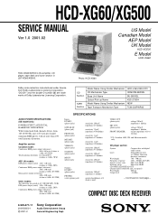
... of Dolby Laboratories Licensing Corporation. Continued on next page - HCD-XG60/XG500 SERVICE MANUAL Ver 1.0 2001.02 US Model Canadian Model AEP Model UK Model HCD-XG500 E Model HCD-XG60 HCD-XG60/XG500 is the amplifier, CD player, tape deck and tuner section in LBT-XG60/XG500. are trademarks of 8 ohms or more than 90 dB CD OPTICAL DIGITAL OUT (Square optical connector jack, rear panel) Wavelength: 660 nm Output level -18 dBm - COMPACT DISC DECK RECEIVER 9-929-577-11 2001B0500-1 C 2001.2 Sony Corporation Audio Entertainment...
... of Dolby Laboratories Licensing Corporation. Continued on next page - HCD-XG60/XG500 SERVICE MANUAL Ver 1.0 2001.02 US Model Canadian Model AEP Model UK Model HCD-XG500 E Model HCD-XG60 HCD-XG60/XG500 is the amplifier, CD player, tape deck and tuner section in LBT-XG60/XG500. are trademarks of 8 ohms or more than 90 dB CD OPTICAL DIGITAL OUT (Square optical connector jack, rear panel) Wavelength: 660 nm Output level -18 dBm - COMPACT DISC DECK RECEIVER 9-929-577-11 2001B0500-1 C 2001.2 Sony Corporation Audio Entertainment...

Service Manual
Page 2
.../XG500 Tape player section Recording system Frequency response (DOLBY NR OFF) 4-track 2-channel stereo 40 - 13,000 Hz (±3 dB), using Sony TYPE I cassette 40 - 14,000 Hz (±3 dB), using Sony TYPE II cassette Tuner section FM stereo, FM/AM superheterodyne tuner FM tuner section Tuning range US, Canadian models: Other models: Antenna Antenna terminals Intermediate frequency 87.5 - 108.0 MHz (100 kHz step) 87.5 - 108.0 MHz (50 kHz step) FM lead antenna 75 ohm...
.../XG500 Tape player section Recording system Frequency response (DOLBY NR OFF) 4-track 2-channel stereo 40 - 13,000 Hz (±3 dB), using Sony TYPE I cassette 40 - 14,000 Hz (±3 dB), using Sony TYPE II cassette Tuner section FM stereo, FM/AM superheterodyne tuner FM tuner section Tuning range US, Canadian models: Other models: Antenna Antenna terminals Intermediate frequency 87.5 - 108.0 MHz (100 kHz step) 87.5 - 108.0 MHz (50 kHz step) FM lead antenna 75 ohm...

Service Manual
Page 3
... 3-9. EXPLODED VIEWS 8-1. ELECTRICAL PARTS LIST 63 6. DIAGRAMS 7-1. Schematic Diagram - Schematic Diagram - MAIN Board (1/3 31 7-15. PA Board 36 7-19. Printed Wiring Boards - Schematic Diagram - GENERAL Location of Controls 6 Setting the Time 7 3. TEST MODE 13 5. Block Diagram - BD Board 25 7-8. Printed Wiring Board - MAIN Board (3/3 33 7-17. MIC/FRONT INPUT/ HEADPHONES Boards 38 7-21. Printed Wiring Board - SERVICING NOTES 5 2. Cover (TC), Tape Mechanism Deck (TCM-230PWR42 9 3-5. CD Mechanism Deck (CDM37M-5BD32L 11 3-8. Printed...
... 3-9. EXPLODED VIEWS 8-1. ELECTRICAL PARTS LIST 63 6. DIAGRAMS 7-1. Schematic Diagram - Schematic Diagram - MAIN Board (1/3 31 7-15. PA Board 36 7-19. Printed Wiring Boards - Schematic Diagram - GENERAL Location of Controls 6 Setting the Time 7 3. TEST MODE 13 5. Block Diagram - BD Board 25 7-8. Printed Wiring Board - MAIN Board (3/3 33 7-17. MIC/FRONT INPUT/ HEADPHONES Boards 38 7-21. Printed Wiring Board - SERVICING NOTES 5 2. Cover (TC), Tape Mechanism Deck (TCM-230PWR42 9 3-5. CD Mechanism Deck (CDM37M-5BD32L 11 3-8. Printed...

Service Manual
Page 4
... releasing the set to the customer: Check the antenna terminals, metal trim, "metallized" knobs, screws, and all exposed metal parts to any exposed metal part having a return to apply force on the rear exterior. SAFETY-RELATED COMPONENT WARNING!! COMPONENTS IDENTIFIED BY MARK 0 OR DOTTED LINE WITH MARK 0 ON THE SCHEMATIC DIAGRAMS AND IN THE PARTS LIST ARE CRITICAL TO SAFE OPERATION.
... releasing the set to the customer: Check the antenna terminals, metal trim, "metallized" knobs, screws, and all exposed metal parts to any exposed metal part having a return to apply force on the rear exterior. SAFETY-RELATED COMPONENT WARNING!! COMPONENTS IDENTIFIED BY MARK 0 OR DOTTED LINE WITH MARK 0 ON THE SCHEMATIC DIAGRAMS AND IN THE PARTS LIST ARE CRITICAL TO SAFE OPERATION.
Service Manual
Page 5
...-087-6[] 5 MODEL US model AEP and UK models 120 V AC area in "CD section adjustment" and check that the S curve waveforms is output three times. Rear Panel - The flexible board is easily damaged and should be focused on clothing and the human body. During repair, pay attention to be handled with care. • MODEL IDENTIFICATION - SECTION 1 SERVICING NOTES HCD-XG60/XG500 NOTES ON...
...-087-6[] 5 MODEL US model AEP and UK models 120 V AC area in "CD section adjustment" and check that the S curve waveforms is output three times. Rear Panel - The flexible board is easily damaged and should be focused on clothing and the human body. During repair, pay attention to be handled with care. • MODEL IDENTIFICATION - SECTION 1 SERVICING NOTES HCD-XG60/XG500 NOTES ON...

Service Manual
Page 6
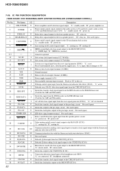
... (18,19) PLAY MODE qk (9,10,17) PHONES jack qh POWER SAVE/DEMO (STANDBY) 2 (8) PTY ws (14) (AEP, UK models) PUSH OPEN wf (9) REPEAT qk (9) SPECTRUM ANALYZER 4 (20) SLEEP 7 (21) STEREO/MONO ws (13) SUPER WOOFER el (18) SUPER WOOFER MODE ek (18) SURROUND ra(16,18) TUNER/BAND wd(12,13,16) TUNER MEMORY wh (12) TIMER SELECT 8 (22) TUNING MODE ws (12,13) VOLUME control qs (9,13...
... (18,19) PLAY MODE qk (9,10,17) PHONES jack qh POWER SAVE/DEMO (STANDBY) 2 (8) PTY ws (14) (AEP, UK models) PUSH OPEN wf (9) REPEAT qk (9) SPECTRUM ANALYZER 4 (20) SLEEP 7 (21) STEREO/MONO ws (13) SUPER WOOFER el (18) SUPER WOOFER MODE ek (18) SURROUND ra(16,18) TUNER/BAND wd(12,13,16) TUNER MEMORY wh (12) TIMER SELECT 8 (22) TUNING MODE ws (12,13) VOLUME control qs (9,13...
Service Manual
Page 7
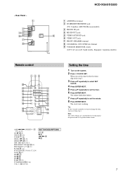
... ENTER/NEXT. Rear Panel - 1 2 3 4 5 6 7 8 HCD-XG60/XG500 1 ANTENNA terminal 2 DJ MIX RETURN/SEND jack (US, Canadian, AEP, UK Mexican models) 3 PHONO IN jack 4 MD IN/OUT jack 9 5 VIDEO/AUDIO IN jack 6 VIDEO OUT jack 7 FRONT SPEAKER terminal 8 CD DIGITAL OUT OPTICAL terminal 9 VOLTAGE SELECTOR switch (120 V AC area in E, Saudi Arabia, Singapore, Argentina models) Remote control 123 ws wa 4 w; 5 ql 6 7 qk 8 qj 9 qh q; The minute indication flashes. 7 Press v/V repeatedly to change the time, start over...
... ENTER/NEXT. Rear Panel - 1 2 3 4 5 6 7 8 HCD-XG60/XG500 1 ANTENNA terminal 2 DJ MIX RETURN/SEND jack (US, Canadian, AEP, UK Mexican models) 3 PHONO IN jack 4 MD IN/OUT jack 9 5 VIDEO/AUDIO IN jack 6 VIDEO OUT jack 7 FRONT SPEAKER terminal 8 CD DIGITAL OUT OPTICAL terminal 9 VOLTAGE SELECTOR switch (120 V AC area in E, Saudi Arabia, Singapore, Argentina models) Remote control 123 ws wa 4 w; 5 ql 6 7 qk 8 qj 9 qh q; The minute indication flashes. 7 Press v/V repeatedly to change the time, start over...
Service Manual
Page 13
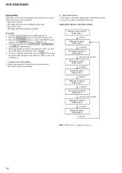
... changed over 9 kHz or 10 kHz. "J" value increases like 0, 9, 8 ... if turn the power ON. 2. The set is plugged in and out. if turn the power OFF. 4. Procedure: 1. Press the ?/1 button to vibration. Press the [LOOP] and ?/1 buttons simultaneously. 3. Select the function "TUNER", and press the [TUNER/BAND] button to initial conditions. The set is activated. 3. "V" value increases like 0, 9, 8 ... SECTION 4 TEST MODE HCD-XG60/XG500 [MC Cold Reset] • The cold reset...
... changed over 9 kHz or 10 kHz. "J" value increases like 0, 9, 8 ... if turn the power ON. 2. The set is plugged in and out. if turn the power OFF. 4. Procedure: 1. Press the ?/1 button to vibration. Press the [LOOP] and ?/1 buttons simultaneously. 3. Select the function "TUNER", and press the [TUNER/BAND] button to initial conditions. The set is activated. 3. "V" value increases like 0, 9, 8 ... SECTION 4 TEST MODE HCD-XG60/XG500 [MC Cold Reset] • The cold reset...
Service Manual
Page 14
... the tape B "TAPE B AG-5" Shut off . 4. To release from the aging mode, press the ?/1 button to turn the power OFF and operate the cold reset. (Refer to select the function "CD". 3. Load the tapes into the decks A and B respectively. 2. HCD-XG60/XG500 [Aging Mode] This mode can be used for operation check of tape deck section alternately. • If an error occurred, stop display that step. Display at the Aging Mode • Display operating state of tape deck section...
... the tape B "TAPE B AG-5" Shut off . 4. To release from the aging mode, press the ?/1 button to turn the power OFF and operate the cold reset. (Refer to select the function "CD". 3. Load the tapes into the decks A and B respectively. 2. HCD-XG60/XG500 [Aging Mode] This mode can be used for operation check of tape deck section alternately. • If an error occurred, stop display that step. Display at the Aging Mode • Display operating state of tape deck section...

Service Manual
Page 15
... ?/1 button to turn the power ON. (2) Select the function "TAPE A or B". (3) Press the button of [ c /CLOCK SET], [ENTER/NEXT], and [DISC 3] simultaneously, to set as follows unless otherwise specified. 8. Demagnetize the record/playback head with the rated power supply voltage unless otherwise noted. 5. tizer. 2. Do not use a magnetized screwdriver for the adjustments. 3. Do not use a magnetized screwdriver for the adjustments. 4. The adjustments should be set the tape deck test mode and displays "TEST MODE...
... ?/1 button to turn the power ON. (2) Select the function "TAPE A or B". (3) Press the button of [ c /CLOCK SET], [ENTER/NEXT], and [DISC 3] simultaneously, to set as follows unless otherwise specified. 8. Demagnetize the record/playback head with the rated power supply voltage unless otherwise noted. 5. tizer. 2. Do not use a magnetized screwdriver for the adjustments. 3. Do not use a magnetized screwdriver for the adjustments. 4. The adjustments should be set the tape deck test mode and displays "TEST MODE...

Service Manual
Page 16
...-48B) Playback Level Adjustment DECK A Procedure: Mode: Playback DECK B test tape P-4-L300 (315 Hz, 0 dB) level meter set + - MAIN board MD OUT jack (J701) L-CH Deck A is RV311 (L-CH), Deck B is RV301 (L-CH) so that outputs match within specification values as follows. L-CH peak within 1dB Output level within ± 0.5 dB Adjustment Location: AUDIO board 16 Press the H button on the LEAF SW board so that frequency counter reads 6,000...
...-48B) Playback Level Adjustment DECK A Procedure: Mode: Playback DECK B test tape P-4-L300 (315 Hz, 0 dB) level meter set + - MAIN board MD OUT jack (J701) L-CH Deck A is RV311 (L-CH), Deck B is RV301 (L-CH) so that outputs match within specification values as follows. L-CH peak within 1dB Output level within ± 0.5 dB Adjustment Location: AUDIO board 16 Press the H button on the LEAF SW board so that frequency counter reads 6,000...

Service Manual
Page 18
...-18) and playback the number five track. 4. Press the H X button. (Becomes the 1 track jump mode) 5. Note: • Try to measure several times to play. 5. Procedure: 1. Connect oscilloscope to peak level within 4 ± 1 Vp-p B E-F Balance (1 Track Jump) Check oscilloscope (DC range) BD board TP (TE) + TP (VC) - Connect between TP (AGCCON) and TP (GND) by lead wire. 3. Load a disc (YEDS-18) and press...
...-18) and playback the number five track. 4. Press the H X button. (Becomes the 1 track jump mode) 5. Note: • Try to measure several times to play. 5. Procedure: 1. Connect oscilloscope to peak level within 4 ± 1 Vp-p B E-F Balance (1 Track Jump) Check oscilloscope (DC range) BD board TP (TE) + TP (VC) - Connect between TP (AGCCON) and TP (GND) by lead wire. 3. Load a disc (YEDS-18) and press...

Service Manual
Page 21
... (2/2) MIC IN REC A2 REC B2 CD-L (Page 19) A PB-L (Page 20) B ST-L (Page 20) D J701 (1/2) L MD IN R R-CH L PHONO IN R R-CH PHONO EQ AMP IC601 INPUT SELECT SWITCH, GRAPHIC EQUALIZER CONTROL, ELECTRICAL VOLUME IN D2 66 67 IN C2 IN B2 68 65 IN E2 69 IN A2 IN F2 64 IC101 INPUT SELECT SWITCH SOUND CONTROL CIRCUIT R-CH L VIDEO AUDIO IN R R-CH GAME INPUT AUDIO J804 (2/2) L R R-CH FUNCTION SELECT SWITCH...
... (2/2) MIC IN REC A2 REC B2 CD-L (Page 19) A PB-L (Page 20) B ST-L (Page 20) D J701 (1/2) L MD IN R R-CH L PHONO IN R R-CH PHONO EQ AMP IC601 INPUT SELECT SWITCH, GRAPHIC EQUALIZER CONTROL, ELECTRICAL VOLUME IN D2 66 67 IN C2 IN B2 68 65 IN E2 69 IN A2 IN F2 64 IC101 INPUT SELECT SWITCH SOUND CONTROL CIRCUIT R-CH L VIDEO AUDIO IN R R-CH GAME INPUT AUDIO J804 (2/2) L R R-CH FUNCTION SELECT SWITCH...

Service Manual
Page 22
... DRIVER IC701 13 DATA 14 CLK 15 STB 4 KEY POWER ON/OFF S609 POWER SAVE/DEMO (STANDBY) 2 KEY POWER SAVE/DEMO SIRCS BUFFER Q608, 609 LED STANDBY 77 REMOTE CONTROL RECEIVER IC702 1 SIRCS S763 (JOG DIAL) ROTARY ENCODER S763 74 JOG A 75 JOG B I2C DATA 78 I2C CLK 79 S736 VOLUME...EXCEPT XG60 : Mexican /XG500 VOLTAGE SELECTOR S901 AC IN RY901 POWER ON/OFF RELAY DRIVE Q901 TC, PANEL, AUDIO A+7V A-7V Q906 ST +10V (FM/AM TUNER UNIT B+) B+ SWITCH Q901, 902 B- BLOCK DIAGRAM - HCD-XG60/XG500 7-4. SWITCH Q903 - 905 +7V REGULATOR IC901 -7V REGULATOR IC951 TUNER B+ SWITCH Q931, 932 +10V ...
... DRIVER IC701 13 DATA 14 CLK 15 STB 4 KEY POWER ON/OFF S609 POWER SAVE/DEMO (STANDBY) 2 KEY POWER SAVE/DEMO SIRCS BUFFER Q608, 609 LED STANDBY 77 REMOTE CONTROL RECEIVER IC702 1 SIRCS S763 (JOG DIAL) ROTARY ENCODER S763 74 JOG A 75 JOG B I2C DATA 78 I2C CLK 79 S736 VOLUME...EXCEPT XG60 : Mexican /XG500 VOLTAGE SELECTOR S901 AC IN RY901 POWER ON/OFF RELAY DRIVE Q901 TC, PANEL, AUDIO A+7V A-7V Q906 ST +10V (FM/AM TUNER UNIT B+) B+ SWITCH Q901, 902 B- BLOCK DIAGRAM - HCD-XG60/XG500 7-4. SWITCH Q903 - 905 +7V REGULATOR IC901 -7V REGULATOR IC951 TUNER B+ SWITCH Q931, 932 +10V ...

Service Manual
Page 23
... a VOM (Input impedance 10 MΩ). F : TUNER (FM/AM) E : TAPE PLAY (DECK A) d : TAPE PLAY (DECK B) G : RECORD J : CD PLAY (ANALOG OUT) c : CD PLAY (DEGITAL OUT) N : MIC INPUT • Abbreviation AR : Argentina model CND : Canadian model E2 : 120 V AC area in Ω and 1/4 W or less unless otherwise specified. • 2 : nonflammable resistor. • 5 : fusible resistor. • C : panel designation. Q BCE These are omitted. Replace only with a oscilloscope. NOTE FOR PRINTED WIRING BOARDS AND SCHEMATIC DIAGRAMS Note...
... a VOM (Input impedance 10 MΩ). F : TUNER (FM/AM) E : TAPE PLAY (DECK A) d : TAPE PLAY (DECK B) G : RECORD J : CD PLAY (ANALOG OUT) c : CD PLAY (DEGITAL OUT) N : MIC INPUT • Abbreviation AR : Argentina model CND : Canadian model E2 : 120 V AC area in Ω and 1/4 W or less unless otherwise specified. • 2 : nonflammable resistor. • 5 : fusible resistor. • C : panel designation. Q BCE These are omitted. Replace only with a oscilloscope. NOTE FOR PRINTED WIRING BOARDS AND SCHEMATIC DIAGRAMS Note...

Service Manual
Page 47
...44 43 42 41 ERROR CORRECTOR 16K RAM DIGITAL PLL EFM DEMODULATOR ASYMMETRY CORRECTOR OPERATIONAL AMPLIFIER ANALOG SWITCH A/D CONVERTER 40 SE 39 FE 38 VC TIMING LOGIC PWM PWM 3rd ORDER NOISE SHAPER OVER SAMPLING DIGITAL FILTER SERIAL IN INTERFACE SUBCODE PROCESSOR SERVO INTERFACE SERVO AUTO SEQUENCER CPU INTERFACE SERVO DSP FOCUS SERVO TRACKING ... 28 27 26 25 24 23 22 F R R INTERFACE F F INTERFACE F RR F INTERFACE R F R 1 2 3 4 5 6 7 21 20 19 18 17 16 15 MUTE LEVEL SHIFT THERMAL SHUTDOWN 8 9 10 11 12 13 14 47 HCD-XG60/XG500 • IC Block...
...44 43 42 41 ERROR CORRECTOR 16K RAM DIGITAL PLL EFM DEMODULATOR ASYMMETRY CORRECTOR OPERATIONAL AMPLIFIER ANALOG SWITCH A/D CONVERTER 40 SE 39 FE 38 VC TIMING LOGIC PWM PWM 3rd ORDER NOISE SHAPER OVER SAMPLING DIGITAL FILTER SERIAL IN INTERFACE SUBCODE PROCESSOR SERVO INTERFACE SERVO AUTO SEQUENCER CPU INTERFACE SERVO DSP FOCUS SERVO TRACKING ... 28 27 26 25 24 23 22 F R R INTERFACE F F INTERFACE F RR F INTERFACE R F R 1 2 3 4 5 6 7 21 20 19 18 17 16 15 MUTE LEVEL SHIFT THERMAL SHUTDOWN 8 9 10 11 12 13 14 47 HCD-XG60/XG500 • IC Block...
Service Manual
Page 50
...O Power amplifier on/off selection signal output "L": standby mode, "H": power amplifier on 2 POWER O Power on/off control signal output for the audio system (+5V) and deck, panel, audio system (+7V) and FM/AM tuner unit (+10V) "L": standby mode, "H": power on 3 F-RELAY O Relay drive signal output for the front speaker protect "H": relay on 4 REAR-RELAY O Relay drive signal output for the rear speaker protect "H": relay on Not used (open ) 5 CD-POWER O Power on/off control signal output for the AEP and UK models) 22 AC-CUT I AC off detection signal input from the reset signal...
...O Power amplifier on/off selection signal output "L": standby mode, "H": power amplifier on 2 POWER O Power on/off control signal output for the audio system (+5V) and deck, panel, audio system (+7V) and FM/AM tuner unit (+10V) "L": standby mode, "H": power on 3 F-RELAY O Relay drive signal output for the front speaker protect "H": relay on 4 REAR-RELAY O Relay drive signal output for the rear speaker protect "H": relay on Not used (open ) 5 CD-POWER O Power on/off control signal output for the AEP and UK models) 22 AC-CUT I AC off detection signal input from the reset signal...

Service Manual
Page 51
... clock signal output to the FM/AM tuner unit Internal status detection monitor input from the CXD2587Q (IC101) Laser power control signal output to the CXA2568M (IC103) Serial data latch pulse output to the CXD2587Q (IC101) Reset signal output to the CXD2587Q (IC101) and BA5974FP (IC102) "L": reset Disc status detection signal input terminal Not used (fixed at automatic music sensor "L": music is present, "H": music is not present *1 Table motor (M201) control Terminal Mode Stop...
... clock signal output to the FM/AM tuner unit Internal status detection monitor input from the CXD2587Q (IC101) Laser power control signal output to the CXA2568M (IC103) Serial data latch pulse output to the CXD2587Q (IC101) Reset signal output to the CXD2587Q (IC101) and BA5974FP (IC102) "L": reset Disc status detection signal input terminal Not used (fixed at automatic music sensor "L": music is present, "H": music is not present *1 Table motor (M201) control Terminal Mode Stop...

Service Manual
Page 52
A play detect switch (S1001) "H": deck-A play I Detection signal input from the deck-B side reel pulse detector (IC1002) I Shut off I Setting terminal for the CD adjustment mode Not used (fixed at "L") I Model setting terminal - HCD-XG60/XG500 Pin No. 78 Pin Name TC-MUTE 79 R/PB/PAS 80 NR-ON/OFF 81 REC-MUTE 82 BIAS 83 EQ-H/N 84 PB-A/B 85 ALC 86 B-PLAY-SW 87 A-PLAY-SW 88 A-HALF 89...
A play detect switch (S1001) "H": deck-A play I Detection signal input from the deck-B side reel pulse detector (IC1002) I Shut off I Setting terminal for the CD adjustment mode Not used (fixed at "L") I Model setting terminal - HCD-XG60/XG500 Pin No. 78 Pin Name TC-MUTE 79 R/PB/PAS 80 NR-ON/OFF 81 REC-MUTE 82 BIAS 83 EQ-H/N 84 PB-A/B 85 ALC 86 B-PLAY-SW 87 A-PLAY-SW 88 A-HALF 89...

Service Manual
Page 53
... - HCD-XG60/XG500 • PANEL FL BOARD IC601 TMP88CP76F-1B71 (FLUORESCENT INDICATOR TUBE DRIVER, KEY CONTROL) Pin No. 1 Pin Name SIRCS 2 KEY POWER SAVE/DEMO 3 LED SCK 4 KEY POWER ON/OFF 5 LED DAT 6 LED LATCH 7 LED SEL 8 WAKE UP 9 VOL A 10 VOL B 11 KEY 0 I/O Description I Remote control signal input from the remote control receiver (IC702) Power save/demonstration switch (S609 POWER SAVE/DEMO (STANDBY)) input terminal I "L" is input when key pressing Remote control signal input from...
... - HCD-XG60/XG500 • PANEL FL BOARD IC601 TMP88CP76F-1B71 (FLUORESCENT INDICATOR TUBE DRIVER, KEY CONTROL) Pin No. 1 Pin Name SIRCS 2 KEY POWER SAVE/DEMO 3 LED SCK 4 KEY POWER ON/OFF 5 LED DAT 6 LED LATCH 7 LED SEL 8 WAKE UP 9 VOL A 10 VOL B 11 KEY 0 I/O Description I Remote control signal input from the remote control receiver (IC702) Power save/demonstration switch (S609 POWER SAVE/DEMO (STANDBY)) input terminal I "L" is input when key pressing Remote control signal input from...

