Service Manual
Page 2
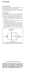
... AC milliammeter. REPLACE THESE COMPONENTS WITH SONY PARTS WHOSE PART NUMBERS APPEAR AS SHOWN IN THIS MANUAL OR IN SUPPLEMENTS PUBLISHED BY SONY. 2 LEAKAGE TEST The AC leakage from any exposed metal part to earth ground and from all other exposed metal parts for this job. 3. Measuring the voltage...: Check the antenna terminals, metal trim, "metallized" knobs, screws, and all exposed metal parts to any one of a passive VOM that have an accurate low-voltage scale. HCD-SH2000 SAFETY CHECK-OUT After correcting the original service problem, perform the following safety check before releasing...
... AC milliammeter. REPLACE THESE COMPONENTS WITH SONY PARTS WHOSE PART NUMBERS APPEAR AS SHOWN IN THIS MANUAL OR IN SUPPLEMENTS PUBLISHED BY SONY. 2 LEAKAGE TEST The AC leakage from any exposed metal part to earth ground and from all other exposed metal parts for this job. 3. Measuring the voltage...: Check the antenna terminals, metal trim, "metallized" knobs, screws, and all exposed metal parts to any one of a passive VOM that have an accurate low-voltage scale. HCD-SH2000 SAFETY CHECK-OUT After correcting the original service problem, perform the following safety check before releasing...
Service Manual
Page 3
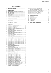
... Printed Wiring Boards - Printed Wiring Boards - AUDIO-IN Board 51 5-37. MIC Board 52 5-39. Schematic Diagram - EXPLODED VIEWS 6-1. HCD-SH2000 TABLE OF CONTENTS 1. RS SERVO, USB Section 15 5-2. Block Diagram - Printed Wiring Board - MAIN Board (1/4) (Suffix 11) ... -... 26 5-12. Schematic Diagram - MAIN Board (3/4) (Suffix 12) - .. 30 5-16. DMB21 Board (Conductor Side 33 5-19. ELECTRICAL PARTS LIST 70 3 DMB21 Board (Component Side 32 5-18. Printed Wiring Board - MAIN Board (Component Side) (Suffix 12 22 5-8. MAIN Board (4/4)...
... Printed Wiring Boards - Printed Wiring Boards - AUDIO-IN Board 51 5-37. MIC Board 52 5-39. Schematic Diagram - EXPLODED VIEWS 6-1. HCD-SH2000 TABLE OF CONTENTS 1. RS SERVO, USB Section 15 5-2. Block Diagram - Printed Wiring Board - MAIN Board (1/4) (Suffix 11) ... -... 26 5-12. Schematic Diagram - MAIN Board (3/4) (Suffix 12) - .. 30 5-16. DMB21 Board (Conductor Side 33 5-19. ELECTRICAL PARTS LIST 70 3 DMB21 Board (Component Side 32 5-18. Printed Wiring Board - MAIN Board (Component Side) (Suffix 12 22 5-8. MAIN Board (4/4)...
Service Manual
Page 4
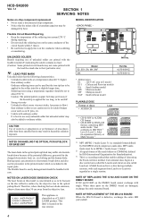
... the objective lens. NOTE OF REPLACING THE IC102 AND IC4605 ON THE DMB21 BOARD IC102 and IC4605 on the conductor when soldering or unsoldering. HCD-SH2000 Ver. 1.1 SECTION 1 SERVICING NOTES Notes on chip component replacement • Never reuse a disconnected chip component. • Notice that conforms ...to ISO 9660 2) Level 1/Level 2, Joliet (in the repair parts. UNLEADED SOLDER Boards requiring use of procedures other than ordinary solder. on the disc reflective surface by heat. NOTES ON LASER...
... the objective lens. NOTE OF REPLACING THE IC102 AND IC4605 ON THE DMB21 BOARD IC102 and IC4605 on the conductor when soldering or unsoldering. HCD-SH2000 Ver. 1.1 SECTION 1 SERVICING NOTES Notes on chip component replacement • Never reuse a disconnected chip component. • Notice that conforms ...to ISO 9660 2) Level 1/Level 2, Joliet (in the repair parts. UNLEADED SOLDER Boards requiring use of procedures other than ordinary solder. on the disc reflective surface by heat. NOTES ON LASER...
Service Manual
Page 5
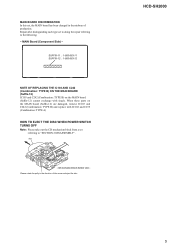
... of the arrow and eject the disc. MAIN BOARD DISCRIMINATION In this set to doing the repair referring to "SECTION 2 DISASSEMBLY". disc - HCD-SH2000 5 MAIN Board (Component Side) - When these parts on the MAIN board (Suffix-12) cannot exchange with IC102 and C239 (Combination: TYPE A) HOW TO EJECT THE DISC WHEN POWER...
... of the arrow and eject the disc. MAIN BOARD DISCRIMINATION In this set to doing the repair referring to "SECTION 2 DISASSEMBLY". disc - HCD-SH2000 5 MAIN Board (Component Side) - When these parts on the MAIN board (Suffix-12) cannot exchange with IC102 and C239 (Combination: TYPE A) HOW TO EJECT THE DISC WHEN POWER...

Service Manual
Page 18
... 19 RESET 12 52 SPK-L-LED-RED 53 SPK-L-LED-BLUE PCONT-MAIN 63 PCONT-SUB 59 54 SPK-R-LED-RED 55 SPK-R-LED-BLUE HCD-SH2000 AVDD +5V DVDD +5V RF +3.3V +3.3V REGULATOR IC107 TU +3.3V VBUS +5V LED +13.5V LED +13.5V TD FL TUBE M +9V ... remove IC103 and C242 (Combination: TYPE B) and replace with single. PANEL, POWER SUPPLY Section - When this part on the MAIN board (Suffix-12) cannot exchange with IC102 and C239 (Combination: TYPE A). HCD-SH2000 5-4. FL9001 FLUORESCENT INDICATOR TUBE GRIDS 1-16 SEGMENTS 1-24 FLUORESCENT INDICATOR TUBE DRIVER IC901 GR1 GR16 SG4/KS4 1 ...
... 19 RESET 12 52 SPK-L-LED-RED 53 SPK-L-LED-BLUE PCONT-MAIN 63 PCONT-SUB 59 54 SPK-R-LED-RED 55 SPK-R-LED-BLUE HCD-SH2000 AVDD +5V DVDD +5V RF +3.3V +3.3V REGULATOR IC107 TU +3.3V VBUS +5V LED +13.5V LED +13.5V TD FL TUBE M +9V ... remove IC103 and C242 (Combination: TYPE B) and replace with single. PANEL, POWER SUPPLY Section - When this part on the MAIN board (Suffix-12) cannot exchange with IC102 and C239 (Combination: TYPE A). HCD-SH2000 5-4. FL9001 FLUORESCENT INDICATOR TUBE GRIDS 1-16 SEGMENTS 1-24 FLUORESCENT INDICATOR TUBE DRIVER IC901 GR1 GR16 SG4/KS4 1 ...

Service Manual
Page 19
... : Chilean and Peruvian models EA : Saudi Arabia model MX : Mexican model MY : Malaysia model SAF : South African model HCD-SH2000 19 19 HCD-SH2000 Ver. 1.1 Line. • Voltage and waveforms are dc with mark 0 are taken with part number specified. • A : B+ Line. • B : B- BE D Q GS These are omitted. • Note for Printed Wiring...
... : Chilean and Peruvian models EA : Saudi Arabia model MX : Mexican model MY : Malaysia model SAF : South African model HCD-SH2000 19 19 HCD-SH2000 Ver. 1.1 Line. • Voltage and waveforms are dc with mark 0 are taken with part number specified. • A : B+ Line. • B : B- BE D Q GS These are omitted. • Note for Printed Wiring...

Service Manual
Page 22
... with IC102 and C239 (Combination: TYPE A). Note 2: A part of circuit composition of MAIN board (Suffix-12) has been changed MAIN board (Suffix-12) appears as TYPE A, and the changed in the midway of production. HCD-SH2000 5-7. C345 USB C BOARD NO1152 (Page 47) VOLUME A ...BOARD CN1000 (Page 45) AUDIO-IN H BOARD NO1200 (Page 51) 12 (12) (CHASSIS) G DAMP BOARD CN1400 (Page 37) B DAMP BOARD CN1401 (Page 37) J HCD-SH2000 Note 1: Refer to distinguish SUFFIX-11 and...
... with IC102 and C239 (Combination: TYPE A). Note 2: A part of circuit composition of MAIN board (Suffix-12) has been changed MAIN board (Suffix-12) appears as TYPE A, and the changed in the midway of production. HCD-SH2000 5-7. C345 USB C BOARD NO1152 (Page 47) VOLUME A ...BOARD CN1000 (Page 45) AUDIO-IN H BOARD NO1200 (Page 51) 12 (12) (CHASSIS) G DAMP BOARD CN1400 (Page 37) B DAMP BOARD CN1401 (Page 37) J HCD-SH2000 Note 1: Refer to distinguish SUFFIX-11 and...
Service Manual
Page 30
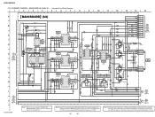
...MAIN board (Suffix-12) that has not been changed appears as TYPE A, and the changed in the midway of production. HCD-SH2000 5-15. SCHEMATIC DIAGRAM - When these parts on the MAIN board (Suffix-12) cannot exchange with IC102 and C239 (Combination: TYPE A). OUTPUT 7 4.5 4.5 3 ... LED DRIVER 3.2 C804 1000p 50V C809 23 24 25 MAIN 6 26 BOARD (4/4) 27 (Page 31) 28 29 30 MAIN 7 BOARD 31 (4/4) 32 (Page 31) HCD-SH2000 Note 1: Refer to the servicing notes "MAIN BOARD DISCRIMINATION" (page 5) for IC Block Diagrams. 1 2 3 4 5 6 7 8 9 10 11 12 13...
...MAIN board (Suffix-12) that has not been changed appears as TYPE A, and the changed in the midway of production. HCD-SH2000 5-15. SCHEMATIC DIAGRAM - When these parts on the MAIN board (Suffix-12) cannot exchange with IC102 and C239 (Combination: TYPE A). OUTPUT 7 4.5 4.5 3 ... LED DRIVER 3.2 C804 1000p 50V C809 23 24 25 MAIN 6 26 BOARD (4/4) 27 (Page 31) 28 29 30 MAIN 7 BOARD 31 (4/4) 32 (Page 31) HCD-SH2000 Note 1: Refer to the servicing notes "MAIN BOARD DISCRIMINATION" (page 5) for IC Block Diagrams. 1 2 3 4 5 6 7 8 9 10 11 12 13...

Service Manual
Page 32
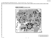
... damaged, exchange the entire mounted board. When this part on the DMB21 board cannot exchange with single. HCD-SH2000 5-17. PRINTED WIRING BOARDS - DMB21 BOARD (Component Side) - • See page 14 for Circuit Boards Location. • : Uses unleaded solder. 1 2 3 4 5 6 7 8 9 10 11 12 13 14 15 A B C D E F G H I J HCD-SH2000 DMB21 BOARD (Component side) NC (CHASSIS) MAIN I BOARD...
... damaged, exchange the entire mounted board. When this part on the DMB21 board cannot exchange with single. HCD-SH2000 5-17. PRINTED WIRING BOARDS - DMB21 BOARD (Component Side) - • See page 14 for Circuit Boards Location. • : Uses unleaded solder. 1 2 3 4 5 6 7 8 9 10 11 12 13 14 15 A B C D E F G H I J HCD-SH2000 DMB21 BOARD (Component side) NC (CHASSIS) MAIN I BOARD...
Service Manual
Page 33
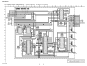
... R237 C219 C226 R239 C222 C224 C221 I R115 R113 R112 R255 R2505 R238 R2502 C225 12 1-883-583- (12) 14 HCD-SH2000 15 J HCD-SH2000 33 33 Note: IC102 on the DMB21 board is damaged, exchange the entire mounted board. PRINTED WIRING BOARDS - When this part on the DMB21 board cannot exchange with single. 5-18.
... R237 C219 C226 R239 C222 C224 C221 I R115 R113 R112 R255 R2505 R238 R2502 C225 12 1-883-583- (12) 14 HCD-SH2000 15 J HCD-SH2000 33 33 Note: IC102 on the DMB21 board is damaged, exchange the entire mounted board. PRINTED WIRING BOARDS - When this part on the DMB21 board cannot exchange with single. 5-18.
Service Manual
Page 34
... 0.1 ET002 E D002 MC2840-T112-1 (CHASSIS) C4622 100p C4623 100p R4833 0 R4834 0 R4867 47 L OUT R OUT C621 0.1 ET001 E (CHASSIS) RESET DATA CLK DATA-SEL HCD-SH2000 34 34 Note: IC4605 on the DMB21 board is damaged, exchange the entire mounted board. SCHEMATIC DIAGRAM - When this part on the DMB21 board cannot exchange with single...
... 0.1 ET002 E D002 MC2840-T112-1 (CHASSIS) C4622 100p C4623 100p R4833 0 R4834 0 R4867 47 L OUT R OUT C621 0.1 ET001 E (CHASSIS) RESET DATA CLK DATA-SEL HCD-SH2000 34 34 Note: IC4605 on the DMB21 board is damaged, exchange the entire mounted board. SCHEMATIC DIAGRAM - When this part on the DMB21 board cannot exchange with single...
Service Manual
Page 65
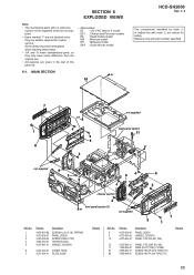
MAIN SECTION #1 10 HCD-SH2000 Ver. 1.1 The components identified by mark 0 or dotted line with mark 0 are seldom required for safety. No. 8 9 10 Part No. 4-275-638-01 4-275-640-01 4-275-642-01 Description PANEL, SIDE A HANDLE, COVER A PANEL, TOP (E2, E51, MX) 10...PANEL, SIDE B SCREW (CASE 3 TP2) +BVTP2.6 (3CR) HANDLE, COVER B 6 4-291-803-01 COVER, HOLE 7 4-277-991-01 PLATE, SONY Remark Ref. SECTION 6 EXPLODED VIEWS Note: • The mechanical parts with no reference number in the exploded views are not supplied. • Items marked "*" are not stocked since they may have...
MAIN SECTION #1 10 HCD-SH2000 Ver. 1.1 The components identified by mark 0 or dotted line with mark 0 are seldom required for safety. No. 8 9 10 Part No. 4-275-638-01 4-275-640-01 4-275-642-01 Description PANEL, SIDE A HANDLE, COVER A PANEL, TOP (E2, E51, MX) 10...PANEL, SIDE B SCREW (CASE 3 TP2) +BVTP2.6 (3CR) HANDLE, COVER B 6 4-291-803-01 COVER, HOLE 7 4-277-991-01 PLATE, SONY Remark Ref. SECTION 6 EXPLODED VIEWS Note: • The mechanical parts with no reference number in the exploded views are not supplied. • Items marked "*" are not stocked since they may have...
Service Manual
Page 66
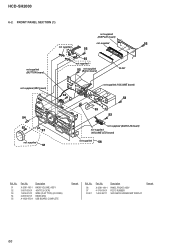
Description X-2581-184-1 PANEL FRONT, ASSY 4-176-619-01 FOOT, RUBBER 1-483-367-11 VACUUM FLUORESCENT DISPLAY Remark 66 HCD-SH2000 6-2. FRONT PANEL SECTION (1) not supplied (DISPLAY board) not supplied 52 not supplied 52 not supplied (BUTTON board) 55 not supplied 52 not supplied (Button board) ...) 52 52 53 52 not supplied (AUDIO-IN board) not supplied (VOLUME LED board) not supplied 56 Ref. No. 56 57 FL901 Part No. No. 51 52 53 54 55 Part No. Description X-2581-185-1 3-087-053-01 1-829-021-51 2-895-507-01 A-1820-972-A KNOB VOLUME, ASSY +BVTP2.6 (3CR) WIRE...
Description X-2581-184-1 PANEL FRONT, ASSY 4-176-619-01 FOOT, RUBBER 1-483-367-11 VACUUM FLUORESCENT DISPLAY Remark 66 HCD-SH2000 6-2. FRONT PANEL SECTION (1) not supplied (DISPLAY board) not supplied 52 not supplied 52 not supplied (BUTTON board) 55 not supplied 52 not supplied (Button board) ...) 52 52 53 52 not supplied (AUDIO-IN board) not supplied (VOLUME LED board) not supplied 56 Ref. No. 56 57 FL901 Part No. No. 51 52 53 54 55 Part No. Description X-2581-185-1 3-087-053-01 1-829-021-51 2-895-507-01 A-1820-972-A KNOB VOLUME, ASSY +BVTP2.6 (3CR) WIRE...
Service Manual
Page 67
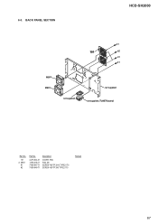
BACK PANEL SECTION HCD-SH2000 #1 101 #2 #1 #1 M891 M891 not supplied not supplied not supplied (TUNER board) Ref. No. 101 0 M891 #1 #2 Part No. 4-275-644-01 1-855-006-11 7-685-647-71 7-685-646-71 Description COVER, FAN FAN, DC SCREW +BVTP 3X10 TYPE2 IT-3 SCREW +BVTP 3X8 TYPE2 IT-3 Remark 67 6-3.
BACK PANEL SECTION HCD-SH2000 #1 101 #2 #1 #1 M891 M891 not supplied not supplied not supplied (TUNER board) Ref. No. 101 0 M891 #1 #2 Part No. 4-275-644-01 1-855-006-11 7-685-647-71 7-685-646-71 Description COVER, FAN FAN, DC SCREW +BVTP 3X10 TYPE2 IT-3 SCREW +BVTP 3X8 TYPE2 IT-3 Remark 67 6-3.

Service Manual
Page 68
... wire (flat type) is replaced, install it after bending it in the same form as that before replacement. No. 158 158 158 159 160 Part No. 1-837-344-11 1-838-939-11 1-838-969-11 1-457-369-12 4-966-267-12 Description Remark CORD, POWER SUPPLY (E2, E51, MX) CORD...-647-71 SCREW +BVTP 3X10 TYPE2 IT-3 #2 7-685-646-71 SCREW +BVTP 3X8 TYPE2 IT-3 #3 7-685-874-09 SCREW +BVTT 3X12(S) 68 HCD-SH2000 Ver. 1.1 6-4. No. 151 152 153 154 155 Part No. CHASSIS SECTION not supplied #3 not supplied 151 159 (SAF, EA) not supplied #1 #1 not supplied (SAF, EA) #1 not supplied not supplied...
... wire (flat type) is replaced, install it after bending it in the same form as that before replacement. No. 158 158 158 159 160 Part No. 1-837-344-11 1-838-939-11 1-838-969-11 1-457-369-12 4-966-267-12 Description Remark CORD, POWER SUPPLY (E2, E51, MX) CORD...-647-71 SCREW +BVTP 3X10 TYPE2 IT-3 #2 7-685-646-71 SCREW +BVTP 3X8 TYPE2 IT-3 #3 7-685-874-09 SCREW +BVTT 3X12(S) 68 HCD-SH2000 Ver. 1.1 6-4. No. 151 152 153 154 155 Part No. CHASSIS SECTION not supplied #3 not supplied 151 159 (SAF, EA) not supplied #1 #1 not supplied (SAF, EA) #1 not supplied not supplied...
Service Manual
Page 69
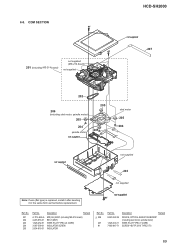
...-618-31 Description Remark MD (AU) ASSY (including MS-214 board) BELT (MOT) WIRE (FLAT TYPE) (24 CORE) INSULATOR SCREW INSULATOR Ref. HCD-SH2000 6-5. not supplied #1 Ref. No. 0 206 207 #1 Part No. 8-820-322-04 1-828-300-11 7-685-647-71 Description Remark DEVICE, OPTICAL KHM-313CAB/C2RP (including sled motor, spindle motor...
...-618-31 Description Remark MD (AU) ASSY (including MS-214 board) BELT (MOT) WIRE (FLAT TYPE) (24 CORE) INSULATOR SCREW INSULATOR Ref. HCD-SH2000 6-5. not supplied #1 Ref. No. 0 206 207 #1 Part No. 8-820-322-04 1-828-300-11 7-685-647-71 Description Remark DEVICE, OPTICAL KHM-313CAB/C2RP (including sled motor, spindle motor...

Service Manual
Page 70
...(RETURN) S1260 1-771-410-21 SWITCH, TACTILE ( -) S1261 1-771-410-21 SWITCH, TACTILE (u) S1262 1-771-410-21 SWITCH, TACTILE (TUNING - When indicating parts by mark 0 or dotted line with part number specified. Replace only with mark 0 are critical for example: uA. . : μA. . , uPA. . , μPA. . , ... each case, u: μ, for safety. HCD-SH2000 Ver. 1.1 AUDIO-IN BUTTON BUTTON LED SECTION 7 ELECTRICAL PARTS LIST Note: • Due to standardization, replacements in the parts list may have some difference from the parts specified in the diagrams or the components...
...(RETURN) S1260 1-771-410-21 SWITCH, TACTILE ( -) S1261 1-771-410-21 SWITCH, TACTILE (u) S1262 1-771-410-21 SWITCH, TACTILE (TUNING - When indicating parts by mark 0 or dotted line with part number specified. Replace only with mark 0 are critical for example: uA. . : μA. . , uPA. . , μPA. . , ... each case, u: μ, for safety. HCD-SH2000 Ver. 1.1 AUDIO-IN BUTTON BUTTON LED SECTION 7 ELECTRICAL PARTS LIST Note: • Due to standardization, replacements in the parts list may have some difference from the parts specified in the diagrams or the components...
Service Manual
Page 75
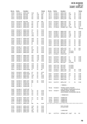
... 5% 1/10W 5% 1/10W 5% 2W 5% 1/10W 5% 2W 5% 1/10W 5% 1/10W 5% 1/10W 5% 1/10W 5% 1/10W 5% 1/10W 5% 1/10W 5% 1/10W 5% 1/10W 5% 1/2W 5% 1/2W 5% 1/10W 5% 1/10W 5% 1/10W 5% 1/10W 5% 1/10W 5% 1/10W Ref. No. Part No. No. HCD-SH2000 Ver. 1.1 DAMP DISPLAY Ref. Description R1710 1-216-837-11 METAL CHIP 22K R1711 1-216-847-11 METAL CHIP 150K R1715 1-216-833-11 METAL...-11 THERMISTOR TH1402 1-804-045-11 THERMISTOR TH1403 1-804-045-11 THERMISTOR DISPLAY BOARD < CAPACITOR > C901 1-127-715-11 CERAMIC CHIP 0.22uF 10% 16V 75 Part No.
... 5% 1/10W 5% 1/10W 5% 2W 5% 1/10W 5% 2W 5% 1/10W 5% 1/10W 5% 1/10W 5% 1/10W 5% 1/10W 5% 1/10W 5% 1/10W 5% 1/10W 5% 1/10W 5% 1/2W 5% 1/2W 5% 1/10W 5% 1/10W 5% 1/10W 5% 1/10W 5% 1/10W 5% 1/10W Ref. No. Part No. No. HCD-SH2000 Ver. 1.1 DAMP DISPLAY Ref. Description R1710 1-216-837-11 METAL CHIP 22K R1711 1-216-847-11 METAL CHIP 150K R1715 1-216-833-11 METAL...-11 THERMISTOR TH1402 1-804-045-11 THERMISTOR TH1403 1-804-045-11 THERMISTOR DISPLAY BOARD < CAPACITOR > C901 1-127-715-11 CERAMIC CHIP 0.22uF 10% 16V 75 Part No.
Service Manual
Page 77
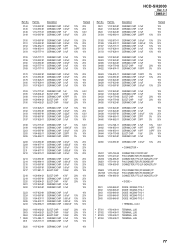
C621 C622 C623 C1504 Part No. 1-107-820-81 1-107-820-81 1-107-820-81 1-162-960-11 Description CERAMIC CHIP CERAMIC CHIP CERAMIC CHIP CERAMIC CHIP 0.1uF 0.1uF... * ET003 * ET004 1-780-408-11 1-780-408-11 1-780-408-11 1-780-408-11 TERMINAL, LUG TERMINAL, LUG TERMINAL, LUG TERMINAL, LUG 77 No. Part No. No. Description Remark C144 C145 C146 C149 1-100-567-81 1-100-567-81 1-112-717-91 1-100-567-81 CERAMIC CHIP CERAMIC CHIP CERAMIC...100uF 100uF 100uF 0.1uF 0.1uF 20% 10V 20% 10V 20% 10V 10% 16V 10% 10V C620 1-107-820-81 CERAMIC CHIP 0.1uF 16V Ref. HCD-SH2000 Ver. 1.1 DMB21 Ref.
C621 C622 C623 C1504 Part No. 1-107-820-81 1-107-820-81 1-107-820-81 1-162-960-11 Description CERAMIC CHIP CERAMIC CHIP CERAMIC CHIP CERAMIC CHIP 0.1uF 0.1uF... * ET003 * ET004 1-780-408-11 1-780-408-11 1-780-408-11 1-780-408-11 TERMINAL, LUG TERMINAL, LUG TERMINAL, LUG TERMINAL, LUG 77 No. Part No. No. Description Remark C144 C145 C146 C149 1-100-567-81 1-100-567-81 1-112-717-91 1-100-567-81 CERAMIC CHIP CERAMIC CHIP CERAMIC...100uF 100uF 100uF 0.1uF 0.1uF 20% 10V 20% 10V 20% 10V 10% 16V 10% 10V C620 1-107-820-81 CERAMIC CHIP 0.1uF 16V Ref. HCD-SH2000 Ver. 1.1 DMB21 Ref.
Service Manual
Page 78
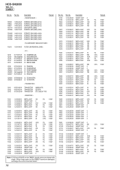
... 0.5% 1/10W 0.5% 1/10W 5% 1/10W 5% 1/16W 5% 1/16W 5% 1/16W 5% 1/16W 5% 1/16W 5% 1/16W 5% 1/16W 5% 1/16W 5% 1/16W 5% 1/16W 0.5% 1/16W 5% 1/16W 5% 1/10W 5% 1/16W 5% 1/10W 5% 1/10W 5% 1/16W 5% 1/16W 5% 1/16W Part No. Part No. Description < FERRITE BEAD > Remark FB108 FB603 FB607 FB1114 FB1264 1-469-324-21 1-469-324-21 1-469-324-21 1-500-903-21 1-469-118-21...5% 1/10W 5% 1/16W 5% 1/16W Note: IC102 and IC4605 on the DMB21 board are damaged, exchange the entire mounted board. 78 Ref. When these parts on the DMB21 board cannot exchange with single. No. HCD-SH2000 Ver. 1.1 DMB21 Ref.
... 0.5% 1/10W 0.5% 1/10W 5% 1/10W 5% 1/16W 5% 1/16W 5% 1/16W 5% 1/16W 5% 1/16W 5% 1/16W 5% 1/16W 5% 1/16W 5% 1/16W 5% 1/16W 0.5% 1/16W 5% 1/16W 5% 1/10W 5% 1/16W 5% 1/10W 5% 1/10W 5% 1/16W 5% 1/16W 5% 1/16W Part No. Part No. Description < FERRITE BEAD > Remark FB108 FB603 FB607 FB1114 FB1264 1-469-324-21 1-469-324-21 1-469-324-21 1-500-903-21 1-469-118-21...5% 1/10W 5% 1/16W 5% 1/16W Note: IC102 and IC4605 on the DMB21 board are damaged, exchange the entire mounted board. 78 Ref. When these parts on the DMB21 board cannot exchange with single. No. HCD-SH2000 Ver. 1.1 DMB21 Ref.


