
Operating Instructions
Page 1
2-660-929-12(1) DVD Home Theatre System Operating Instructions DAV-FX900W ©2006 Sony Corporation
2-660-929-12(1) DVD Home Theatre System Operating Instructions DAV-FX900W ©2006 Sony Corporation

Operating Instructions
Page 2
DAV-FX900W Serial No WARNING This equipment has been tested and found to comply with...not install the unit near heat sources such as practical. Record the serial number in this manual could void your Sony dealer regarding this product. Model No. For the customers in the U.S.A This symbol is intended to alert the ...radiators, or air ducts, or in a residential installation. Increase the separation between the equipment and receiver. - Note to CATV system installer: This reminder is encouraged to try to direct sunlight, excessive dust, mechanical vibration, or shock. • Do not...
DAV-FX900W Serial No WARNING This equipment has been tested and found to comply with...not install the unit near heat sources such as practical. Record the serial number in this manual could void your Sony dealer regarding this product. Model No. For the customers in the U.S.A This symbol is intended to alert the ...radiators, or air ducts, or in a residential installation. Increase the separation between the equipment and receiver. - Note to CATV system installer: This reminder is encouraged to try to direct sunlight, excessive dust, mechanical vibration, or shock. • Do not...

Operating Instructions
Page 3
Thank you move it for purchasing Sony DVD Home Theatre System. Before operating this system, please read this manual thoroughly and retain it from a cold to a warm location, moisture may condense inside the DVD Home Theatre System and cause damage to a warm location, wait for about 30 minutes before operating the unit. Welcome! • If the unit is a registered trademark of XM Satellite Radio Inc. When you first install the unit, or when you for future reference. 3US XM is brought directly from a cold to the lenses.
Thank you move it for purchasing Sony DVD Home Theatre System. Before operating this system, please read this manual thoroughly and retain it from a cold to a warm location, moisture may condense inside the DVD Home Theatre System and cause damage to a warm location, wait for about 30 minutes before operating the unit. Welcome! • If the unit is a registered trademark of XM Satellite Radio Inc. When you first install the unit, or when you for future reference. 3US XM is brought directly from a cold to the lenses.

Operating Instructions
Page 4
...the Following Discs 6 Getting Started - ADVANCED - Step 1: Assembling the Speakers and Installing the Surround Amplifier 10 Step 2: Connecting the System and TV 16 Step 3: Positioning the System ...20 Step 4: Performing the Quick Setup 21 Getting Started - BASIC - Turning off the Demonstration 24 Installing the Speakers and the IR... Selecting a Playback Area for a Super Audio CD 53 About MP3 Audio Tracks and JPEG Image Files 54 Playing DATA CDs or DATA DVDs with MP3 Audio Tracks and JPEG Image Files 56 Playing Audio Tracks and Images as a Slide Show with Sound 58 Playing VIDEO CDs ...
...the Following Discs 6 Getting Started - ADVANCED - Step 1: Assembling the Speakers and Installing the Surround Amplifier 10 Step 2: Connecting the System and TV 16 Step 3: Positioning the System ...20 Step 4: Performing the Quick Setup 21 Getting Started - BASIC - Turning off the Demonstration 24 Installing the Speakers and the IR... Selecting a Playback Area for a Super Audio CD 53 About MP3 Audio Tracks and JPEG Image Files 54 Playing DATA CDs or DATA DVDs with MP3 Audio Tracks and JPEG Image Files 56 Playing Audio Tracks and Images as a Slide Show with Sound 58 Playing VIDEO CDs ...

Operating Instructions
Page 5
... appear in the display) Specifications 92 Glossary 94 Language Code List 98 Index to Parts and Controls 99 Guide to the Control Menu Display.... 102 DVD Setup Display List 105 AMP Menu List 106 Index 107 5US
... appear in the display) Specifications 92 Glossary 94 Language Code List 98 Index to Parts and Controls 99 Guide to the Control Menu Display.... 102 DVD Setup Display List 105 AMP Menu List 106 Index 107 5US

Operating Instructions
Page 6
... on the remote. • The Control Menu items may be different depending on the remote. This System Can Play the Following Discs Format of discs DVD VIDEO Disc logo DVD-RW/ DVD-R DVD+RW/ DVD+R Super Audio CD VIDEO CD (Ver. 1.1 and 2.0 discs)/CD Graphics (Latin American models only)/... this manual describe the controls on the area. • "DVD" may be used as a general term for DVD VIDEOs, DVD+RWs/DVD+Rs, and DVD-RWs/DVD-Rs. • Measurements are expressed in feet (ft) for DATA DVDs (DVD-ROMs/DVD-Rs/ DVD-RWs/DVD+Rs/DVD+RWs) containing MP3* audio tracks, JPEG image files * MP3...
... on the remote. • The Control Menu items may be different depending on the remote. This System Can Play the Following Discs Format of discs DVD VIDEO Disc logo DVD-RW/ DVD-R DVD+RW/ DVD+R Super Audio CD VIDEO CD (Ver. 1.1 and 2.0 discs)/CD Graphics (Latin American models only)/... this manual describe the controls on the area. • "DVD" may be used as a general term for DVD VIDEOs, DVD+RWs/DVD+Rs, and DVD-RWs/DVD-Rs. • Measurements are expressed in feet (ft) for DATA DVDs (DVD-ROMs/DVD-Rs/ DVD-RWs/DVD+Rs/DVD+RWs) containing MP3* audio tracks, JPEG image files * MP3...

Operating Instructions
Page 7
...However, since the audio material side does not conform to ISO 9660 Level 1/ Level 2, or its extended format, Joliet The system can play DVD-ROMs/DVD+RWs/ DVD-RWs/DVD+Rs/DVD-Rs recorded in the following discs: • CD-ROMs/CD-Rs/CD-RWs other side. MP3 audio tracks, JPEG image ... playback. CD Graphics (Latin American models only) - Note about CD-R/CD-RW/DVD-R/ DVD-RW/DVD+R/DVD+RW In some DVD+RWs/DVD+Rs, even if they have been correctly finalized. About Multi Session CD • This system can also be played back. Recently, various music discs encoded with paper or stickers...
...However, since the audio material side does not conform to ISO 9660 Level 1/ Level 2, or its extended format, Joliet The system can play DVD-ROMs/DVD+RWs/ DVD-RWs/DVD+Rs/DVD-Rs recorded in the following discs: • CD-ROMs/CD-Rs/CD-RWs other side. MP3 audio tracks, JPEG image ... playback. CD Graphics (Latin American models only) - Note about CD-R/CD-RW/DVD-R/ DVD-RW/DVD+R/DVD+RW In some DVD+RWs/DVD+Rs, even if they have been correctly finalized. About Multi Session CD • This system can also be played back. Recently, various music discs encoded with paper or stickers...

Operating Instructions
Page 8
"DTS" and "DTS Digital Surround" are trademarks of Dolby Laboratories. ** Manufactured under license from Digital Theater Systems, Inc. Depending on the DVD VIDEO, no region code indication may be intentionally set by area restrictions. Also, refer to the disc contents the ... playing the DVD VIDEO is intended for home and other limited viewing uses only unless otherwise authorized by U.S. "Dolby," "Pro Logic," and the double-D symbol are trademarks of Digital Theater Systems, Inc. 8US Note on playback operations of DVDs and VIDEO CDs Some playback operations of DVDs and VIDEO ...
"DTS" and "DTS Digital Surround" are trademarks of Dolby Laboratories. ** Manufactured under license from Digital Theater Systems, Inc. Depending on the DVD VIDEO, no region code indication may be intentionally set by area restrictions. Also, refer to the disc contents the ... playing the DVD VIDEO is intended for home and other limited viewing uses only unless otherwise authorized by U.S. "Dolby," "Pro Logic," and the double-D symbol are trademarks of Digital Theater Systems, Inc. 8US Note on playback operations of DVDs and VIDEO CDs Some playback operations of DVDs and VIDEO ...

Operating Instructions
Page 9
... of the subwoofer to use a new battery with an old one. • Do not drop any foreign object into the remote You can control the system using the remote, point it from slipping. 9US Insert two R6 (size AA) batteries by matching the 3 and # ends on the... system. Doing so may cause a malfunction. • If you do not intend to stabilize the subwoofer and prevent it at the remote sensor on the batteries ...
... of the subwoofer to use a new battery with an old one. • Do not drop any foreign object into the remote You can control the system using the remote, point it from slipping. 9US Insert two R6 (size AA) batteries by matching the 3 and # ends on the... system. Doing so may cause a malfunction. • If you do not intend to stabilize the subwoofer and prevent it at the remote sensor on the batteries ...

Operating Instructions
Page 10
Step 1: Assembling the Speakers and Installing the Surround Amplifier Before connecting the speakers, attach the speaker stand to the SPEAKER jacks, see page 17. Tip • You can use . Post (long) or Post (short) Base 2 Secure the base with washer (long) (3) (supplied) 10US Bottom of the base Note • Spread a cloth on the wall (page 25). 1 Secure the post to install the surround speaker (L). Screws with the screws. The long post is for floor use, the short post is for the surround speaker (L) only. The IR receiver cord should be used for tabletop use the ...
Step 1: Assembling the Speakers and Installing the Surround Amplifier Before connecting the speakers, attach the speaker stand to the SPEAKER jacks, see page 17. Tip • You can use . Post (long) or Post (short) Base 2 Secure the base with washer (long) (3) (supplied) 10US Bottom of the base Note • Spread a cloth on the wall (page 25). 1 Secure the post to install the surround speaker (L). Screws with the screws. The long post is for floor use, the short post is for the surround speaker (L) only. The IR receiver cord should be used for tabletop use the ...

Operating Instructions
Page 11
Fold back about 700 mm (28 inch). IR receiver cord , Speaker cord 5 Secure the pedestal to a straight length of the base Untwist and straighten out the speaker cord. About 100 mm (4 inch) 4 Draw the IR receiver cord first, and then the speaker cord through the hole on the base. Screws with the screws. Stand the speaker up, and untwist and straighten out the speaker cord. Bottom of about 100 mm (4 inch) and twist together. BASIC - 3 Pull the speaker cord out to the post with washer (long) (3) (supplied) continued 11US Getting Started -
Fold back about 700 mm (28 inch). IR receiver cord , Speaker cord 5 Secure the pedestal to a straight length of the base Untwist and straighten out the speaker cord. About 100 mm (4 inch) 4 Draw the IR receiver cord first, and then the speaker cord through the hole on the base. Screws with the screws. Stand the speaker up, and untwist and straighten out the speaker cord. Bottom of about 100 mm (4 inch) and twist together. BASIC - 3 Pull the speaker cord out to the post with washer (long) (3) (supplied) continued 11US Getting Started -

Operating Instructions
Page 12
Then run the cord around the pin. 7 Connect the speaker cords to the speaker and run the cords through the slots (A, B, C, and D) all the way. A B C D 12US BASIC - 6 Connect the IR receiver cord to the speaker. Getting Started -
Then run the cord around the pin. 7 Connect the speaker cords to the speaker and run the cords through the slots (A, B, C, and D) all the way. A B C D 12US BASIC - 6 Connect the IR receiver cord to the speaker. Getting Started -

Operating Instructions
Page 13
Adjust the length of the speaker cord (and the IR receiver cord). Note • Lay the surround speakers down slowly onto the pedestal. The illustrations below show how to attach the surround speaker (L) to the speaker base. Note • Do not catch the speaker cord (and the IR receiver cord) between the speaker and the pedestal. • Do not drop the speaker when mounting. 9 Secure the speaker with the screws in order 1 to 2. 1 2 Screws with washer (short) (2) (supplied) Installing the surround amplifier (speaker base) You can put on the surround speaker (L) to the surround ...
Adjust the length of the speaker cord (and the IR receiver cord). Note • Lay the surround speakers down slowly onto the pedestal. The illustrations below show how to attach the surround speaker (L) to the speaker base. Note • Do not catch the speaker cord (and the IR receiver cord) between the speaker and the pedestal. • Do not drop the speaker when mounting. 9 Secure the speaker with the screws in order 1 to 2. 1 2 Screws with washer (short) (2) (supplied) Installing the surround amplifier (speaker base) You can put on the surround speaker (L) to the surround ...

Operating Instructions
Page 14
Run cords through the slot. 14US Screws (4) (supplied) BASIC - 1 Attach the spacers. Spacers (4) (supplied) Guide pins (2) (supplied) Push open the cover (surround amplifier only). 2 Attach the surround amplifier (speaker base) to the circle marked holes. Rear of surround speaker 3 Secure the surround amplifier (speaker base) with the screws to the surround speaker with the guide pins. Getting Started -
Run cords through the slot. 14US Screws (4) (supplied) BASIC - 1 Attach the spacers. Spacers (4) (supplied) Guide pins (2) (supplied) Push open the cover (surround amplifier only). 2 Attach the surround amplifier (speaker base) to the circle marked holes. Rear of surround speaker 3 Secure the surround amplifier (speaker base) with the screws to the surround speaker with the guide pins. Getting Started -

Operating Instructions
Page 15
From surround speaker (L). Stand the speaker up. SS-TS56W From surround speaker (R). SUR R SPEAKER SUR L 5 Bundle the cords into the storage space. Storage space 15US BASIC - 4 Connect the speaker cords and the IR receiver cord to the surround amplifier. Getting Started - The speaker base has storage space in the back. , Attach the cover (surround amplifier only).
From surround speaker (L). Stand the speaker up. SS-TS56W From surround speaker (R). SUR R SPEAKER SUR L 5 Bundle the cords into the storage space. Storage space 15US BASIC - 4 Connect the speaker cords and the IR receiver cord to the surround amplifier. Getting Started - The speaker base has storage space in the back. , Attach the cover (surround amplifier only).

Operating Instructions
Page 16
...VIDEO IN COMPONENT VIDEO IN Y PB/CB PR/CR R AUDIO IN L VIDEO IN TV/VCR2 Y PB/CB PR/CR COMPONENT VIDEO OUT XM S VIDEO (DVD ONLY) AM VIDEO MONITOR OUT FM 75 COAXIAL B AUDIO OUT L VIDEO IN R A Subwoofer Surround speaker (R) IR transmitter FM wire antenna (aerial) TV Surround... SS-TS56W AC power cord (mains lead) BASIC - To accept progressive signals, see page 31. Step 2: Connecting the System and TV This hookup is the basic connection of the system to 4 on the following pages. Refer to the connection diagram below, and read the additional information from 1 to the...
...VIDEO IN COMPONENT VIDEO IN Y PB/CB PR/CR R AUDIO IN L VIDEO IN TV/VCR2 Y PB/CB PR/CR COMPONENT VIDEO OUT XM S VIDEO (DVD ONLY) AM VIDEO MONITOR OUT FM 75 COAXIAL B AUDIO OUT L VIDEO IN R A Subwoofer Surround speaker (R) IR transmitter FM wire antenna (aerial) TV Surround... SS-TS56W AC power cord (mains lead) BASIC - To accept progressive signals, see page 31. Step 2: Connecting the System and TV This hookup is the basic connection of the system to 4 on the following pages. Refer to the connection diagram below, and read the additional information from 1 to the...
Operating Instructions
Page 17
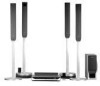
... touch another speaker terminal or the bare wire of each other than the one currently displayed on the Setup Display, the speaker may damage the system. Note • Be sure to match the speaker cord to the appropriate terminal on outputting a test tone, see page 84. Getting Started - To prevent this...
... touch another speaker terminal or the bare wire of each other than the one currently displayed on the Setup Display, the speaker may damage the system. Note • Be sure to match the speaker cord to the appropriate terminal on outputting a test tone, see page 84. Getting Started - To prevent this...

Operating Instructions
Page 18
... AM loop antenna (aerial). 3 Connect the cords to the AM antenna (aerial) terminals. Note • Do not place the AM loop antenna (aerial) near the system or other AV equipment, as noise may result. Tip • Adjust the direction of the antenna (aerial) is connected firmly by pulling softly. 18US BASIC...
... AM loop antenna (aerial). 3 Connect the cords to the AM antenna (aerial) terminals. Note • Do not place the AM loop antenna (aerial) near the system or other AV equipment, as noise may result. Tip • Adjust the direction of the antenna (aerial) is connected firmly by pulling softly. 18US BASIC...
Operating Instructions
Page 19
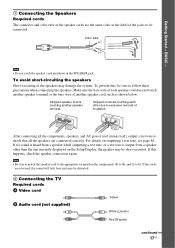
... as horizontal as shown below. Tip • If you have poor FM reception, use a 75-ohm coaxial cable (not supplied) to connect the system to the system. 19US BASIC - Getting Started - System Outdoor FM antenna (aerial) 4 Connecting the AC power cord (mains lead) Before connecting the AC power cord (mains lead) of this...
... as horizontal as shown below. Tip • If you have poor FM reception, use a 75-ohm coaxial cable (not supplied) to connect the system to the system. 19US BASIC - Getting Started - System Outdoor FM antenna (aerial) 4 Connecting the AC power cord (mains lead) Before connecting the AC power cord (mains lead) of this...

Operating Instructions
Page 20
... a specially treated (waxed, oiled, polished, etc.) floor, as staining or discoloration may fall down. For details, see "Getting Optimal Surround Sound for this system only. • Do not step on the surround amplifier and speaker base. • When you change the settings. Subject to vibrations - Dusty or dirty .... • Do not set the speakers in an inclined position. • Do not place the speakers in a place exposed to the system by the speaker cords (OPTION) (supplied). • When you change the positions of the surround speaker (L)" (page 23). Step 3: Positioning the...
... a specially treated (waxed, oiled, polished, etc.) floor, as staining or discoloration may fall down. For details, see "Getting Optimal Surround Sound for this system only. • Do not step on the surround amplifier and speaker base. • When you change the settings. Subject to vibrations - Dusty or dirty .... • Do not set the speakers in an inclined position. • Do not place the speakers in a place exposed to the system by the speaker cords (OPTION) (supplied). • When you change the positions of the surround speaker (L)" (page 23). Step 3: Positioning the...