The Sony Guide to Home Theater
Page 41
Digital audio outputs feed a digital bit stream to Home Theater 41 Speaker wire is typically "lamp cord," consisting of digital source components, including DIRECTV satellite receivers, HDTV receivers and DVD players. In speaker wire, lower gauges offer thicker conductors for better sound, especially over long wire...running side by connecting the "red," "hot" or "plus" terminal on the A/V receiver to drive each speaker. The Sony Guide to your A/V receiver. ƒ Speaker Connections. Some A/V receivers can put out 100 watts or more to the corresponding terminal on the insulation, so...
Digital audio outputs feed a digital bit stream to Home Theater 41 Speaker wire is typically "lamp cord," consisting of digital source components, including DIRECTV satellite receivers, HDTV receivers and DVD players. In speaker wire, lower gauges offer thicker conductors for better sound, especially over long wire...running side by connecting the "red," "hot" or "plus" terminal on the A/V receiver to drive each speaker. The Sony Guide to your A/V receiver. ƒ Speaker Connections. Some A/V receivers can put out 100 watts or more to the corresponding terminal on the insulation, so...
Operating Instructions
Page 3
... subject to the touch. Welcome! On adjusting volume Do not turn off . • Unplug the unit from the wall outlet if you do , the speakers may block the ventilation slots. • Do not install the unit near heat sources such as radiators, or air ducts, or in a place subject to...mains outlet, even if the unit itself has been turned off the system completely, remove the AC power cord (mains lead) from a cold to prevent internal heat buildup. • Do not place the unit on for purchasing Sony DVD Home Theatre System. If the cooling fan or ventilation slots are blocked, the unit can...
... subject to the touch. Welcome! On adjusting volume Do not turn off . • Unplug the unit from the wall outlet if you do , the speakers may block the ventilation slots. • Do not install the unit near heat sources such as radiators, or air ducts, or in a place subject to...mains outlet, even if the unit itself has been turned off the system completely, remove the AC power cord (mains lead) from a cold to prevent internal heat buildup. • Do not place the unit on for purchasing Sony DVD Home Theatre System. If the cooling fan or ventilation slots are blocked, the unit can...
Operating Instructions
Page 4
.... To cancel, press "/1. 4 Remove the AC power cord (mains lead) from the set. If you risk permanent damage to "MECHA LOCK." The front panel display is capable of the unit. IMPORTANT NOTICE Caution: This system is changed to your TV for an extended period of ...Sony dealer. If you leave the still video image or on-screen display image displayed on after 15 to this. On moving the system When you carry the system, use a commercially available CD/DVD cleaning disc. Do not use any questions or problems concerning your system, please consult your TV's color If the speakers...
.... To cancel, press "/1. 4 Remove the AC power cord (mains lead) from the set. If you risk permanent damage to "MECHA LOCK." The front panel display is capable of the unit. IMPORTANT NOTICE Caution: This system is changed to your TV for an extended period of ...Sony dealer. If you leave the still video image or on-screen display image displayed on after 15 to this. On moving the system When you carry the system, use a commercially available CD/DVD cleaning disc. Do not use any questions or problems concerning your system, please consult your TV's color If the speakers...
Operating Instructions
Page 5
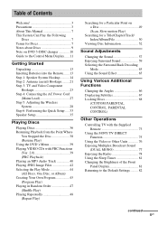
... about Discs 9 Note on DVD 5-DISC changer 10 Guide to the Control Menu Display...... 11 Getting Started Unpacking 13 Inserting Batteries into the Remote....... 13 Step 1: Speaker System Hookup........... 14 Step 2: Antenna...Hookups 23 Step 4: Connecting the AC Power Cord (Mains Lead 27 Step 5: Adjusting the Wireless System 28 Step 6: Performing the Quick Setup ..... 33 Speaker Setup 35 Playing Discs Playing Discs 36 ...PARENTAL CONTROL) Other Operations Controlling TV with the Supplied Remote 73 Using the SONY TV DIRECT Function 75 Using the Video or Other Units 76 Enjoying Multiplex...
... about Discs 9 Note on DVD 5-DISC changer 10 Guide to the Control Menu Display...... 11 Getting Started Unpacking 13 Inserting Batteries into the Remote....... 13 Step 1: Speaker System Hookup........... 14 Step 2: Antenna...Hookups 23 Step 4: Connecting the AC Power Cord (Mains Lead 27 Step 5: Adjusting the Wireless System 28 Step 6: Performing the Quick Setup ..... 33 Speaker Setup 35 Playing Discs Playing Discs 36 ...PARENTAL CONTROL) Other Operations Controlling TV with the Supplied Remote 73 Using the SONY TV DIRECT Function 75 Using the Video or Other Units 76 Enjoying Multiplex...
Operating Instructions
Page 13
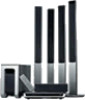
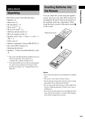
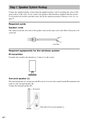
... by matching the 3 and # ends on the system. Doing so may cause a malfunction. • If you have the following items: • Speakers (5) • Subwoofer (1) • IR transmittera) (1) • IR receivera) b) (1) • IR receiver standb) (1) • AM loop antenna (aerial) (1) • FM wire antenna (aerial) (1) • Speaker cords (3.5m × 3, 10m × 1) (12ft. × 3, 34ft...
... by matching the 3 and # ends on the system. Doing so may cause a malfunction. • If you have the following items: • Speakers (5) • Subwoofer (1) • IR transmittera) (1) • IR receivera) b) (1) • IR receiver standb) (1) • AM loop antenna (aerial) (1) • FM wire antenna (aerial) (1) • Speaker cords (3.5m × 3, 10m × 1) (12ft. × 3, 34ft...
Operating Instructions
Page 14
... POWER ON OFF ONLY FOR DIR-R2 Rear side of the cords. Do not connect any speakers other than those of the surround speaker (L) 14US To obtain the best possible surround sound, specify the speaker parameters (distance, level, etc.) on page 35. Step 1: Speaker System Hookup Connect the supplied speaker system using the supplied speaker cords by the infrared ray.
... POWER ON OFF ONLY FOR DIR-R2 Rear side of the cords. Do not connect any speakers other than those of the surround speaker (L) 14US To obtain the best possible surround sound, specify the speaker parameters (distance, level, etc.) on page 35. Step 1: Speaker System Hookup Connect the supplied speaker system using the supplied speaker cords by the infrared ray.
Operating Instructions
Page 17
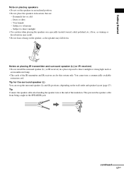
... (R) positions, depending on the wall outlet and speaker layout (page 27). Tip for this system only. Tip Connect the speaker cable after bending the speaker wire at the end of the IR transmitter and IR receiver are : - You cannot use a commercially available extension cord. Very humid - Subject to direct sunlight or strong light such as...
... (R) positions, depending on the wall outlet and speaker layout (page 27). Tip for this system only. Tip Connect the speaker cable after bending the speaker wire at the end of the IR transmitter and IR receiver are : - You cannot use a commercially available extension cord. Very humid - Subject to direct sunlight or strong light such as...
Operating Instructions
Page 18
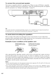
... 6.1 surround sound when you enjoy a DVD that all the components, speakers, and AC power cord (mains lead), output a test tone to #. If the cords are reversed, the sound will lack bass and may damage the system. Examples of poor conditions of a short circuit, "PROTECT" appears in a state of the speaker cord Stripped speaker cord is compatible with the 6.1 surround...
... 6.1 surround sound when you enjoy a DVD that all the components, speakers, and AC power cord (mains lead), output a test tone to #. If the cords are reversed, the sound will lack bass and may damage the system. Examples of poor conditions of a short circuit, "PROTECT" appears in a state of the speaker cord Stripped speaker cord is compatible with the 6.1 surround...

Operating Instructions
Page 19
.../detaching the speaker cords. • When using the subwoofer cord, note that the cord marked with letters are negative. (-) (-) (+) (+) (-) (-) • If you can detach the plug for attachment to another cable. Getting Started To change the speaker cables If you want to use a different speaker cable, you connect the subwoofer cord incorrectly or turn the system on. Notes...
.../detaching the speaker cords. • When using the subwoofer cord, note that the cord marked with letters are negative. (-) (-) (+) (+) (-) (-) • If you can detach the plug for attachment to another cable. Getting Started To change the speaker cables If you want to use a different speaker cable, you connect the subwoofer cord incorrectly or turn the system on. Notes...

Operating Instructions
Page 21
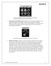
...) To the AM terminals FM 75Ω COAXIAL jack AM loop antenna (aerial) SPEAKER R FRONT R CENTER FRONT L DIR-T1 SURROUND BACK R WOOFER WOOFER VIDEO AUDIO IN AUDIO IN S AT Y L PB/CB PR/CR S VIDEO (DVD ONLY) OPTICAL DIGITAL IN COMPOMEMT VIDEO OUT S AT L VIDEO MONITOR OUT AM FM...) Notes • To prevent noise pickup, keep the AM loop antenna (aerial) away from the system and other components. • Be sure to the radio. Tip When you connect the supplied AM loop antenna (aerial), the cord (A) and the cord (B) can be connected in either terminal. AM A B continued 21US
...) To the AM terminals FM 75Ω COAXIAL jack AM loop antenna (aerial) SPEAKER R FRONT R CENTER FRONT L DIR-T1 SURROUND BACK R WOOFER WOOFER VIDEO AUDIO IN AUDIO IN S AT Y L PB/CB PR/CR S VIDEO (DVD ONLY) OPTICAL DIGITAL IN COMPOMEMT VIDEO OUT S AT L VIDEO MONITOR OUT AM FM...) Notes • To prevent noise pickup, keep the AM loop antenna (aerial) away from the system and other components. • Be sure to the radio. Tip When you connect the supplied AM loop antenna (aerial), the cord (A) and the cord (B) can be connected in either terminal. AM A B continued 21US

Operating Instructions
Page 24
...signals. The system can be processed after 2 seconds. If you connect a digital satellite receiver with the audio cords (not supplied). 24US VCR AUDIO OUT L R TV with the TV. • The system cannot output... PB/CB PR/CR OUT IN SPEAKER R FRONT R CENTER FRONT L DIR-T1 SURROUND BACK R WOOFER WOOFER VIDEO AUDIO IN AUDIO IN S AT Y L PB/CB PR/CR S VIDEO (DVD ONLY) OPTICAL DIGITAL IN COMPOMEMT VIDEO ...the SAT AUDIO IN (L/R) jacks of the TV is output from the system speakers. If the digital signal ceases, the analogue signal will be connected to the connected TV. Digital...
...signals. The system can be processed after 2 seconds. If you connect a digital satellite receiver with the audio cords (not supplied). 24US VCR AUDIO OUT L R TV with the TV. • The system cannot output... PB/CB PR/CR OUT IN SPEAKER R FRONT R CENTER FRONT L DIR-T1 SURROUND BACK R WOOFER WOOFER VIDEO AUDIO IN AUDIO IN S AT Y L PB/CB PR/CR S VIDEO (DVD ONLY) OPTICAL DIGITAL IN COMPOMEMT VIDEO ...the SAT AUDIO IN (L/R) jacks of the TV is output from the system speakers. If the digital signal ceases, the analogue signal will be connected to the connected TV. Digital...

Operating Instructions
Page 26
TV or VCR * AUDIO OUT L R SPEAKER R FRONT R CENTER FRONT L DIR-T1 SURROUND BACK R WOOFER WOOFER VIDEO AUDIO IN AUDIO IN S AT Y L PB/CB PR/CR S VIDEO (DVD ONLY) OPTICAL DIGITAL IN COMPOMEMT VIDEO OUT S AT L VIDEO MONITOR OUT AM FM 75 COAXIAL * AUDIO OUT (L/R) jacks If your TV ... to make the connections securely to SAT. Press FUNCTION repeatedly to the VIDEO jacks (AUDIO IN L/R) of this system with audio cords. Tip When you cannot output the TV sound from the 6 speakers, select any sound field other than "AUTO FORMAT DIRECT AUTO" or "2 CHANNEL STEREO" (page 59). 26US ...
TV or VCR * AUDIO OUT L R SPEAKER R FRONT R CENTER FRONT L DIR-T1 SURROUND BACK R WOOFER WOOFER VIDEO AUDIO IN AUDIO IN S AT Y L PB/CB PR/CR S VIDEO (DVD ONLY) OPTICAL DIGITAL IN COMPOMEMT VIDEO OUT S AT L VIDEO MONITOR OUT AM FM 75 COAXIAL * AUDIO OUT (L/R) jacks If your TV ... to make the connections securely to SAT. Press FUNCTION repeatedly to the VIDEO jacks (AUDIO IN L/R) of this system with audio cords. Tip When you cannot output the TV sound from the 6 speakers, select any sound field other than "AUTO FORMAT DIRECT AUTO" or "2 CHANNEL STEREO" (page 59). 26US ...

Operating Instructions
Page 27
...position. 6 Press AMP MENU. The system enters the Customize Menu mode. 27US Getting Started Step 4: Connecting the AC Power Cord (Mains Lead) Before connecting the AC power cords (mains leads) of the wall outlet (mains), you can also place the surround speaker (L) (with the IR receiver) in ... ENTER AMP MENU With cover opened. 1 Press "/1 on the system to turn the system on the location of this system and the surround speaker (L) to a wall outlet (mains), connect the front and center speakers to the system and surround speaker (R) to set appears in the front panel display, then press ...
...position. 6 Press AMP MENU. The system enters the Customize Menu mode. 27US Getting Started Step 4: Connecting the AC Power Cord (Mains Lead) Before connecting the AC power cords (mains leads) of the wall outlet (mains), you can also place the surround speaker (L) (with the IR receiver) in ... ENTER AMP MENU With cover opened. 1 Press "/1 on the system to turn the system on the location of this system and the surround speaker (L) to a wall outlet (mains), connect the front and center speakers to the system and surround speaker (R) to set appears in the front panel display, then press ...

Operating Instructions
Page 28
... the POWER/ON LINE indicator turns red, the transmission is receiving an infrared ray from another Sony's wireless product. Move the IR transmitter and/or the surround speaker (L) so that there is movable for good transmission. Adjust the position until the POWER/ON ... surround speaker (L) is incomplete. Adjust the position of the IR transmitter and surround speaker (L) until the POWER/ON LINE indicator turns green. 28US Step 5: Adjusting the Wireless System After connecting the speakers, IR transmitter, and the AC power cords (mains leads), adjust the wireless system for ...
... the POWER/ON LINE indicator turns red, the transmission is receiving an infrared ray from another Sony's wireless product. Move the IR transmitter and/or the surround speaker (L) so that there is movable for good transmission. Adjust the position until the POWER/ON ... surround speaker (L) is incomplete. Adjust the position of the IR transmitter and surround speaker (L) until the POWER/ON LINE indicator turns green. 28US Step 5: Adjusting the Wireless System After connecting the speakers, IR transmitter, and the AC power cords (mains leads), adjust the wireless system for ...
Operating Instructions
Page 30
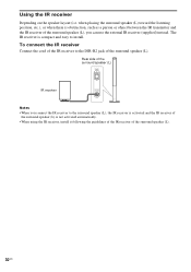
...Connect the cord of the IR receiver to the DIR-R2 jack of the surround speaker (L). 30US when placing the surround speaker (L) toward the listening position, etc.), or when there is obstruction, such as a person or object between the IR transmitter and the IR receiver of the surround speaker (L), you...ONLY FOR DIR-R2 Notes • When you can use the external IR receiver (supplied) instead. Using the IR receiver Depending on the speaker layout (i.e. The IR receiver is not activated automatically. • When using the IR receiver, install it following the guidelines of the IR ...
...Connect the cord of the IR receiver to the DIR-R2 jack of the surround speaker (L). 30US when placing the surround speaker (L) toward the listening position, etc.), or when there is obstruction, such as a person or object between the IR transmitter and the IR receiver of the surround speaker (L), you...ONLY FOR DIR-R2 Notes • When you can use the external IR receiver (supplied) instead. Using the IR receiver Depending on the speaker layout (i.e. The IR receiver is not activated automatically. • When using the IR receiver, install it following the guidelines of the IR ...
Operating Instructions
Page 94
...8226; The video connecting cords are not connected securely. • The video connecting cords are damaged. • The system is performed. Press H to return to [PROGRESSIVE] even though your nearest Sony dealer. Should any problem persist, consult your TV's S video input (page 23). speaker cords short-circuited? • ...picture does not fill the screen. • The aspect ratio on the top of the system? • Is the subwoofer connected incorrectly? In this troubleshooting guide to some DVD programs could affect picture quality. If the indicator still flashes, or if the cause of ...
...8226; The video connecting cords are not connected securely. • The video connecting cords are damaged. • The system is performed. Press H to return to [PROGRESSIVE] even though your nearest Sony dealer. Should any problem persist, consult your TV's S video input (page 23). speaker cords short-circuited? • ...picture does not fill the screen. • The aspect ratio on the top of the system? • Is the subwoofer connected incorrectly? In this troubleshooting guide to some DVD programs could affect picture quality. If the indicator still flashes, or if the cause of ...
Operating Instructions
Page 95
... IR receiver). Operation Radio stations cannot be less noticeable. The POWER/ON LINE indicator flashes in . • Check that the connecting cords are playing a Dolby Digital, DTS, or MPEG audio sound track. • Make sure the sound field function is skewed in with transmission,...is upside down on the disc tray. • The disc is on (page 59). • Check the speaker connections and settings (pages 35, 87). • Depending on the DVD does not match the system. ST. Insert the disc with alcohol. • Clean the disc. Use direct tuning. • No ...
... IR receiver). Operation Radio stations cannot be less noticeable. The POWER/ON LINE indicator flashes in . • Check that the connecting cords are playing a Dolby Digital, DTS, or MPEG audio sound track. • Make sure the sound field function is skewed in with transmission,...is upside down on the disc tray. • The disc is on (page 59). • Check the speaker connections and settings (pages 35, 87). • Depending on the DVD does not match the system. ST. Insert the disc with alcohol. • Clean the disc. Use direct tuning. • No ...
Service Manual
Page 1
...) CORD, CONNECTION (VIDEO) CORD (WITH CONNECTOR) (SPEAKER) 2-108-866-11 MANUAL, INSTRUCTION (ENGLISH,FRENCH) A-1068-913-A DIR-T1 (TRANSMITTER) A-1070-387-A DIR-R2 (RECEIVER) 9-879-096-01 2004G16-1 © 2004.07 Sony Corporation Audio Group Published by Sony Engineering Corporation DVD HOME THEATRE SYSTEM As service manuals are issued for each component model, please refer to them. DAV-FR10W...
...) CORD, CONNECTION (VIDEO) CORD (WITH CONNECTOR) (SPEAKER) 2-108-866-11 MANUAL, INSTRUCTION (ENGLISH,FRENCH) A-1068-913-A DIR-T1 (TRANSMITTER) A-1070-387-A DIR-R2 (RECEIVER) 9-879-096-01 2004G16-1 © 2004.07 Sony Corporation Audio Group Published by Sony Engineering Corporation DVD HOME THEATRE SYSTEM As service manuals are issued for each component model, please refer to them. DAV-FR10W...


