The Sony Guide to Home Theater
Page 41
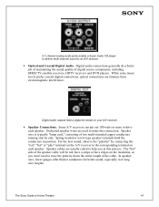
.... Spring-loaded or screw-type speaker terminals hold the conductors in this connection. In speaker wire, lower gauges offer thicker conductors for better sound, especially over long wire lengths. The Sony Guide to drive each speaker. For the best sound, observe the "polarity" by side.... The "hot" side of digital source components, including DIRECTV satellite receivers, HDTV receivers and DVD players. Some A/V receivers can put ...
.... Spring-loaded or screw-type speaker terminals hold the conductors in this connection. In speaker wire, lower gauges offer thicker conductors for better sound, especially over long wire lengths. The Sony Guide to drive each speaker. For the best sound, observe the "polarity" by side.... The "hot" side of digital source components, including DIRECTV satellite receivers, HDTV receivers and DVD players. Some A/V receivers can put ...
The Sony Guide to Home Theater
Page 47
...as much data for a Subwoofer. dts (Digital Theater System) decoder. Sound track encoding system that is dynamic, spacious and realistic. Sony's top receivers offer DSP modes that add a Surround ...group of Sony developments that decodes and amplifies the surround channels already encoded in big-screen television. To enable multi-channel music reproduction from a DVD player, satellite...discrete 6.1 and dts ES matrix 6.1. same wire. Digital Television (DTV). Picture quality is a digital output from conventional, stereo sources, Sony engineers have captured the sound of 24-bit ...
...as much data for a Subwoofer. dts (Digital Theater System) decoder. Sound track encoding system that is dynamic, spacious and realistic. Sony's top receivers offer DSP modes that add a Surround ...group of Sony developments that decodes and amplifies the surround channels already encoded in big-screen television. To enable multi-channel music reproduction from a DVD player, satellite...discrete 6.1 and dts ES matrix 6.1. same wire. Digital Television (DTV). Picture quality is a digital output from conventional, stereo sources, Sony engineers have captured the sound of 24-bit ...
Operating Instructions
Page 13
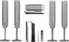
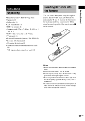
Doing so may cause a malfunction. • If you have the following items: • Speakers (5) • Subwoofer (1) • AM loop antenna (1) • FM wire antenna (1) • Speaker cords (3.5m × 3, 10m × 2) (12ft. × 3, 34ft. × 2) • Subwoofer cord (3.5m) (11ft 5 7/8in.) • Video cord (1) ...to direct light from battery leakage and corrosion. 13US Insert two R6 (size AA) batteries by matching the 3 and # ends on the system. Getting Started Getting Started Unpacking Check that you do not use a new battery with an old one. • Do not drop any ...
Doing so may cause a malfunction. • If you have the following items: • Speakers (5) • Subwoofer (1) • AM loop antenna (1) • FM wire antenna (1) • Speaker cords (3.5m × 3, 10m × 2) (12ft. × 3, 34ft. × 2) • Subwoofer cord (3.5m) (11ft 5 7/8in.) • Video cord (1) ...to direct light from battery leakage and corrosion. 13US Insert two R6 (size AA) batteries by matching the 3 and # ends on the system. Getting Started Getting Started Unpacking Check that you do not use a new battery with an old one. • Do not drop any ...

Operating Instructions
Page 16
... short-circuiting the speakers Short-circuiting of each other than the one currently displayed in the front panel display, the speaker may damage the system. Note Be sure to match the speaker cord to the appropriate terminal on outputting a test tone, see page 72. Tip Connect the ...# to follow these precautions when connecting the speakers. Note Do not catch the speaker cable insulation in the SPEAKER jack. Make sure the bare wire of the speakers may be distorted. 16US If the cords are connected correctly. This prevents the speaker cable from a speaker other due to check...
... short-circuiting the speakers Short-circuiting of each other than the one currently displayed in the front panel display, the speaker may damage the system. Note Be sure to match the speaker cord to the appropriate terminal on outputting a test tone, see page 72. Tip Connect the ...# to follow these precautions when connecting the speakers. Note Do not catch the speaker cable insulation in the SPEAKER jack. Make sure the bare wire of the speakers may be distorted. 16US If the cords are connected correctly. This prevents the speaker cable from a speaker other due to check...

Operating Instructions
Page 17
... the cords from plug. AWG #24. • Before attaching a new cable, strip off 10 mm (13/32 in.) of its insulation and twist the bare wires of both cords. 10 mm 17US Attaching While pressing the plug down against a flat surface, insert the new speaker cords. Note Be careful not to...
... the cords from plug. AWG #24. • Before attaching a new cable, strip off 10 mm (13/32 in.) of its insulation and twist the bare wires of both cords. 10 mm 17US Attaching While pressing the plug down against a flat surface, insert the new speaker cords. Note Be careful not to...

Operating Instructions
Page 18
... can be connected in either terminal. Step 2: Antenna Hookups Connect the supplied AM/FM antennas for connecting the antennas Connect the AM loop antenna FM wire antenna To the AM terminals FM 75Ω COAXIAL jack FRONT R CENTER FRONT L SURR R SURR L SUB WOOFER AUDIO OUT SPEAKER AM loop ...VIDEO AUDIO IN R L VIDEO IN S VIDEO Y PB/CB PR/CR COMPONENT VIDEO OUT OPTICAL DIGITAL IN VIDEO 2 AM FM 75 COAXIAL FM wire antenna Notes • To prevent noise pickup, keep the AM loop antenna away from the system and other components. • Be sure to the radio. A AM B 18US
... can be connected in either terminal. Step 2: Antenna Hookups Connect the supplied AM/FM antennas for connecting the antennas Connect the AM loop antenna FM wire antenna To the AM terminals FM 75Ω COAXIAL jack FRONT R CENTER FRONT L SURR R SURR L SUB WOOFER AUDIO OUT SPEAKER AM loop ...VIDEO AUDIO IN R L VIDEO IN S VIDEO Y PB/CB PR/CR COMPONENT VIDEO OUT OPTICAL DIGITAL IN VIDEO 2 AM FM 75 COAXIAL FM wire antenna Notes • To prevent noise pickup, keep the AM loop antenna away from the system and other components. • Be sure to the radio. A AM B 18US

Operating Instructions
Page 78
... RMS power, with no sound output. Super Audio CD/DVD system Laser Semiconductor laser (Super Audio CD/DVD: λ = 650 nm) (CD: λ = 780 nm) Emission duration: continuous Signal format system NTSC or NTSC/PAL Frequency response (at 2 CH STEREO mode) DVD (PCM): 2 Hz to 22 kHz (±1.0 dB... range Antenna Antenna terminals Intermediate frequency AM tuner section Tuning range Antenna Intermediate frequency PLL quartz-locked digital synthesizer system 87.5 - 108.0 MHz (100 kHz step) FM wire antenna 75 ohms, unbalanced 10.7 MHz 531 - 1,710 kHz (with the interval set at 10 kHz)...
... RMS power, with no sound output. Super Audio CD/DVD system Laser Semiconductor laser (Super Audio CD/DVD: λ = 650 nm) (CD: λ = 780 nm) Emission duration: continuous Signal format system NTSC or NTSC/PAL Frequency response (at 2 CH STEREO mode) DVD (PCM): 2 Hz to 22 kHz (±1.0 dB... range Antenna Antenna terminals Intermediate frequency AM tuner section Tuning range Antenna Intermediate frequency PLL quartz-locked digital synthesizer system 87.5 - 108.0 MHz (100 kHz step) FM wire antenna 75 ohms, unbalanced 10.7 MHz 531 - 1,710 kHz (with the interval set at 10 kHz)...


