
Limited Warranty (US Only)
Page 1
...Disc Players/Audio Systems Hifi Audio LIMITED WARRANTY Sony Electronics Inc. ("Sony") warrants this Product is invalid if the factory applied serial number has been altered or removed from the Product. This warranty does not cover damage due to improper operation or maintenance, connection to improper ...voltage supply, or attempted repair by Sony to obtain warranty service. This warranty is valid only in exchange for defective parts for all labor ...
...Disc Players/Audio Systems Hifi Audio LIMITED WARRANTY Sony Electronics Inc. ("Sony") warrants this Product is invalid if the factory applied serial number has been altered or removed from the Product. This warranty does not cover damage due to improper operation or maintenance, connection to improper ...voltage supply, or attempted repair by Sony to obtain warranty service. This warranty is valid only in exchange for defective parts for all labor ...
Operating Instructions
Page 2
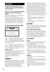
... period of the unit. Note to CATV system installer: This reminder is not disconnected from the AC power source (mains) as long as vases, on the apparatus. However, there is encouraged to try to persons. Model No. DAV-DX355/DAV-DX375 Serial No WARNING This equipment has been tested...connected to the wall outlet (mains), even if the unit itself has been turned off and on, the user is no guarantee that may be determined by one or more of the following measures: - The use it any changes or modifications not expressly approved in this manual could void your Sony...
... period of the unit. Note to CATV system installer: This reminder is not disconnected from the AC power source (mains) as long as vases, on the apparatus. However, there is encouraged to try to persons. Model No. DAV-DX355/DAV-DX375 Serial No WARNING This equipment has been tested...connected to the wall outlet (mains), even if the unit itself has been turned off and on, the user is no guarantee that may be determined by one or more of the following measures: - The use it any changes or modifications not expressly approved in this manual could void your Sony...
Operating Instructions
Page 4
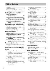
... Timer 63 Changing the Brightness of Contents Welcome 3 About This Manual 6 This System Can Play the Following Discs 7 Getting Started - ADVANCED - Table of the Front Panel Display 63 4US Step 1: Assembling the Speakers 10 Step 2: Connecting the System and TV 13 Step 3: Positioning the System ...18 Step 4: Performing the Quick Setup 19 Getting Started -
... Timer 63 Changing the Brightness of Contents Welcome 3 About This Manual 6 This System Can Play the Following Discs 7 Getting Started - ADVANCED - Table of the Front Panel Display 63 4US Step 1: Assembling the Speakers 10 Step 2: Connecting the System and TV 13 Step 3: Positioning the System ...18 Step 4: Performing the Quick Setup 19 Getting Started -

Operating Instructions
Page 10
BASIC - Bottom of DAV-DX375 only.) Note • Spread a cloth on the base, then stand it on the wall (page 23). 1 Secure the post to avoid damaging the floor. Step 1: Assembling the Speakers Before connecting the speakers, attach the speaker stand to the speaker. (For the front speakers of the base , Speaker cord 10US Post Base 2 Draw the speaker cord through the hole on the floor to the base. Tip • You can use the speaker without the speaker stand by installing it up. Getting Started -
BASIC - Bottom of DAV-DX375 only.) Note • Spread a cloth on the base, then stand it on the wall (page 23). 1 Secure the post to avoid damaging the floor. Step 1: Assembling the Speakers Before connecting the speakers, attach the speaker stand to the speaker. (For the front speakers of the base , Speaker cord 10US Post Base 2 Draw the speaker cord through the hole on the floor to the base. Tip • You can use the speaker without the speaker stand by installing it up. Getting Started -

Operating Instructions
Page 11
Securing the pedestal forcibly may ruin the screw threads. 4 Connect the speaker cords to the post. A B C D continued 11US BASIC - 3 Secure the pedestal to the speaker, then run them through the slots (A, B, C, and D) all the way. Getting Started - Note • If it is hard to secure the pedestal, remove and secure it again.
Securing the pedestal forcibly may ruin the screw threads. 4 Connect the speaker cords to the post. A B C D continued 11US BASIC - 3 Secure the pedestal to the speaker, then run them through the slots (A, B, C, and D) all the way. Getting Started - Note • If it is hard to secure the pedestal, remove and secure it again.
Operating Instructions
Page 13
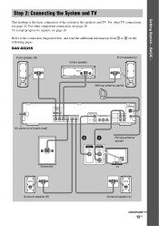
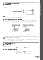
... TV This hookup is the basic connection of the system to 4 on the following pages. For other component connection, see page 28. To accept progressive signals, see page 24. DAV-DX355 Front speaker (R) Center speaker Front speaker (L) AM loop antenna (aerial) AC power cord (mains lead) (DVD... antenna (aerial) Subwoofer VIDEO IN AUDIO OUT L R TV Surround speaker (R) Surround speaker (L) continued 13US For other TV connections, see page 26. Refer to the connection diagram below, and read the additional information from 1 to the speakers and TV. BASIC - Getting Started -
... TV This hookup is the basic connection of the system to 4 on the following pages. For other component connection, see page 28. To accept progressive signals, see page 24. DAV-DX355 Front speaker (R) Center speaker Front speaker (L) AM loop antenna (aerial) AC power cord (mains lead) (DVD... antenna (aerial) Subwoofer VIDEO IN AUDIO OUT L R TV Surround speaker (R) Surround speaker (L) continued 13US For other TV connections, see page 26. Refer to the connection diagram below, and read the additional information from 1 to the speakers and TV. BASIC - Getting Started -
Operating Instructions
Page 15
...speakers Short-circuiting of the jacks to follow these precautions when connecting the speakers. If this , be sure to be connected. If the cords are connected correctly. To prevent this happens, check the speaker connection again. Stripped cords are touching each speaker cord does not touch... B Audio cord (not supplied) Yellow White (L/audio) Red (R/audio) continued 15US Getting Started - After connecting all the speakers are reversed, the sound will lack bass and may damage the system. If no sound is heard from a speaker while outputting a test tone, or a test tone is ...
...speakers Short-circuiting of the jacks to follow these precautions when connecting the speakers. If this , be sure to be connected. If the cords are connected correctly. To prevent this happens, check the speaker connection again. Stripped cords are touching each speaker cord does not touch... B Audio cord (not supplied) Yellow White (L/audio) Red (R/audio) continued 15US Getting Started - After connecting all the speakers are reversed, the sound will lack bass and may damage the system. If no sound is heard from a speaker while outputting a test tone, or a test tone is ...
Operating Instructions
Page 16
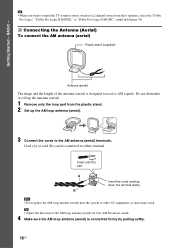
... Logic II MOVIE," or "Dolby Pro Logic II MUSIC" sound field (page 34). 3 Connecting the Antenna (Aerial) To connect the AM antenna (aerial) Plastic stand (supplied) Antenna (aerial) The shape and the length...AM loop antenna (aerial) is designed to either terminal. Cord (A) or cord (B) can be connected to receive AM signals. A B AM Insert the cords pushing down the terminal clamp. Do not ... the AM loop antenna (aerial). 3 Connect the cords to the AM antenna (aerial) terminals. Tip • Adjust the direction of the antenna (aerial) is connected firmly by pulling softly. 16US BASIC -...
... Logic II MOVIE," or "Dolby Pro Logic II MUSIC" sound field (page 34). 3 Connecting the Antenna (Aerial) To connect the AM antenna (aerial) Plastic stand (supplied) Antenna (aerial) The shape and the length...AM loop antenna (aerial) is designed to either terminal. Cord (A) or cord (B) can be connected to receive AM signals. A B AM Insert the cords pushing down the terminal clamp. Do not ... the AM loop antenna (aerial). 3 Connect the cords to the AM antenna (aerial) terminals. Tip • Adjust the direction of the antenna (aerial) is connected firmly by pulling softly. 16US BASIC -...
Operating Instructions
Page 17
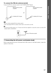
... as horizontal as shown below. BASIC - To connect the FM wire antenna (aerial) Connect the FM wire antenna (aerial) to the system. 17US System Outdoor FM antenna (aerial) 4 Connecting the AC power cord (mains lead) Before connecting the AC power cord (mains lead) of this system to a wall outlet (mains), connect the speakers to the COAXIAL FM 75...
... as horizontal as shown below. BASIC - To connect the FM wire antenna (aerial) Connect the FM wire antenna (aerial) to the system. 17US System Outdoor FM antenna (aerial) 4 Connecting the AC power cord (mains lead) Before connecting the AC power cord (mains lead) of this system to a wall outlet (mains), connect the speakers to the COAXIAL FM 75...

Operating Instructions
Page 19
...minimum number of the TV to select the setting that the signal from the system appears on -screen display appears. Note • Disconnect the headphones when you have a wide-screen TV or a 4:3 standard TV with the headphones connected. • Make sure that the function is set to run QUICK SETUP.]... appears at the bottom of the screen. The system displays the menu and subtitles in the on the TV screen. [Press [ENTER] to "...
...minimum number of the TV to select the setting that the signal from the system appears on -screen display appears. Note • Disconnect the headphones when you have a wide-screen TV or a 4:3 standard TV with the headphones connected. • Make sure that the function is set to run QUICK SETUP.]... appears at the bottom of the screen. The system displays the menu and subtitles in the on the TV screen. [Press [ENTER] to "...
Operating Instructions
Page 20
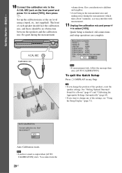
...calibration mic and select YES. Tip • If you want to change the position of the speakers, reset the speaker settings. AUTO CALIBRATION Connect calibration mic. You cannot turn the 20US The front of the settings, see "Using the Setup Display" (page 71). Give consideration to ...at the ear level using a tripod, etc. (not supplied). A.CAL MIC Calibration mic volume down. All connections and setup operations are complete. Measurement complete. Getting Started - BASIC - 10 Connect the calibration mic to the A.CAL MIC jack on the front panel and press X/x to select [YES]. Be...
...calibration mic and select YES. Tip • If you want to change the position of the speakers, reset the speaker settings. AUTO CALIBRATION Connect calibration mic. You cannot turn the 20US The front of the settings, see "Using the Setup Display" (page 71). Give consideration to ...at the ear level using a tripod, etc. (not supplied). A.CAL MIC Calibration mic volume down. All connections and setup operations are complete. Measurement complete. Getting Started - BASIC - 10 Connect the calibration mic to the A.CAL MIC jack on the front panel and press X/x to select [YES]. Be...
Operating Instructions
Page 22
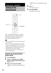
Getting Started - The AMP menu turns off , the system saves power in the AMP menu to select the setting. • DEMO ON: sets the demonstration mode on the remote. When the demonstration mode is ... off . The setting is set the demonstration mode to off . Note • When you press "/1 on the system, the demonstration does not turn off. • When you press "/1 on . 22US ADVANCED - X/x/c, AMP MENU After connecting the AC power cord (mains lead), the demonstration appears in the front panel display, then press or...
Getting Started - The AMP menu turns off , the system saves power in the AMP menu to select the setting. • DEMO ON: sets the demonstration mode on the remote. When the demonstration mode is ... off . The setting is set the demonstration mode to off . Note • When you press "/1 on the system, the demonstration does not turn off. • When you press "/1 on . 22US ADVANCED - X/x/c, AMP MENU After connecting the AC power cord (mains lead), the demonstration appears in the front panel display, then press or...

Operating Instructions
Page 24
Picture quality improves in order from A (standard) to a TV. The system incorporates High-Definition Multimedia Interface (HDMITM) technology. 24US Check the jacks of High-Definition Multimedia Interface Specifications. D TV with HDMI* jack IN To HDMI*...with VIDEO IN jack TV with S VIDEO IN jack * HDMI (high-definition multimedia interface) TV with COMPONENT VIDEO IN jacks The system is based on your TV, and choose connection method A, B, C, or D. Connecting the video/HDMI* cords Sends a played back DVD image to D (HDMI). TV Hookup (Advanced) Select a hookup suitable for the...
Picture quality improves in order from A (standard) to a TV. The system incorporates High-Definition Multimedia Interface (HDMITM) technology. 24US Check the jacks of High-Definition Multimedia Interface Specifications. D TV with HDMI* jack IN To HDMI*...with VIDEO IN jack TV with S VIDEO IN jack * HDMI (high-definition multimedia interface) TV with COMPONENT VIDEO IN jacks The system is based on your TV, and choose connection method A, B, C, or D. Connecting the video/HDMI* cords Sends a played back DVD image to D (HDMI). TV Hookup (Advanced) Select a hookup suitable for the...

Operating Instructions
Page 25
... 25US The DVI (digital visual interface) jack will not be output through the HDMI OUT (high-definition multimedia interface out) jack. When connecting to a TV with DVI (digital visual interface) input Use an HDMI (high-definition multimedia interface)-DVI (digital visual interface) converter cord ...HDMI OUT (high-definition multimedia interface out) jack. If your TV monitor must use this connection and set the output channel of the system to a TV with the COMPONENT VIDEO IN jacks Connect a component video cord (not supplied). S video signals are not HDCP (high-bandwidth digital ...
... 25US The DVI (digital visual interface) jack will not be output through the HDMI OUT (high-definition multimedia interface out) jack. When connecting to a TV with DVI (digital visual interface) input Use an HDMI (high-definition multimedia interface)-DVI (digital visual interface) converter cord ...HDMI OUT (high-definition multimedia interface out) jack. If your TV monitor must use this connection and set the output channel of the system to a TV with the COMPONENT VIDEO IN jacks Connect a component video cord (not supplied). S video signals are not HDCP (high-bandwidth digital ...

Operating Instructions
Page 26
"PROGRE" lights up in the front panel display when the system outputs progressive signals. 1 Press FUNCTION +/- x P VIDEO (PROGRESSIVE VIDEO) Select this method, you need to connect to a TV that the picture will not be clear or no picture will appear if you want to fix the conversion method to the ...COMPONENT VIDEO OUT jacks. the TV is connected to PROGRESSIVE VIDEO for displaying TV images which reduces flickering, and sharpens the image. Note that the picture will not be clear or no ...
"PROGRE" lights up in the front panel display when the system outputs progressive signals. 1 Press FUNCTION +/- x P VIDEO (PROGRESSIVE VIDEO) Select this method, you need to connect to a TV that the picture will not be clear or no picture will appear if you want to fix the conversion method to the ...COMPONENT VIDEO OUT jacks. the TV is connected to PROGRESSIVE VIDEO for displaying TV images which reduces flickering, and sharpens the image. Note that the picture will not be clear or no ...

Operating Instructions
Page 27
... as dramas and sit-coms, and displays images at 24 frames per second. your TV does not accept progressive signals, or, - Video-based software is connected to appear natural on your screen when output in the interlace format. 27US Some DVD software contains both video and film. Even though you play...
... as dramas and sit-coms, and displays images at 24 frames per second. your TV does not accept progressive signals, or, - Video-based software is connected to appear natural on your screen when output in the interlace format. 27US Some DVD software contains both video and film. Even though you play...

Operating Instructions
Page 28
...can enjoy sound using the audio cord (not supplied). Connecting the system and the other component Outputs the other components to the TV or VCR (AUDIO IN) jacks of this system. For video connection of this system Connect the VCR or other component through the speakers of other... components, connect directly to the appropriate jacks on the components. VCR, digital satellite receiver or PlayStation ...
...can enjoy sound using the audio cord (not supplied). Connecting the system and the other component Outputs the other components to the TV or VCR (AUDIO IN) jacks of this system. For video connection of this system Connect the VCR or other component through the speakers of other... components, connect directly to the appropriate jacks on the components. VCR, digital satellite receiver or PlayStation ...

Operating Instructions
Page 29
... portable audio source sound through the system Connect the audio output jacks of the system with the stereo mini-plug cord (not supplied). Press SOUND FIELD repeatedly until "A.F.D. Press FUNCTION +/- STD" appears in the front panel display. To cancel, select other than "A.F.D. Note • Be sure to make connections securely to the AUDIO IN...
... portable audio source sound through the system Connect the audio output jacks of the system with the stereo mini-plug cord (not supplied). Press SOUND FIELD repeatedly until "A.F.D. Press FUNCTION +/- STD" appears in the front panel display. To cancel, select other than "A.F.D. Note • Be sure to make connections securely to the AUDIO IN...
Operating Instructions
Page 30
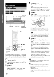
...other discs, press DISC 1-5 (that the disc is loaded in the front panel display. The system starts playback (continuous play ). off: there is no disc is being played back. - Basic Operations Disc tray DISC 1-5 Connect headphones "/1 / X DISC SKIP MUTING VOLUME +/- ./> H x FUNCTION +/- Refer to this... Adjust the volume on . Basic Operations Playing Discs Adjust the "/1 A H FUNCTION volume 4 Press DISC 1-5. Press the button of the system. Place one disc on the inner circle of the tray. Depending on the DVD VIDEO or VIDEO CD, some operations may not appear on...
...other discs, press DISC 1-5 (that the disc is loaded in the front panel display. The system starts playback (continuous play ). off: there is no disc is being played back. - Basic Operations Disc tray DISC 1-5 Connect headphones "/1 / X DISC SKIP MUTING VOLUME +/- ./> H x FUNCTION +/- Refer to this... Adjust the volume on . Basic Operations Playing Discs Adjust the "/1 A H FUNCTION volume 4 Press DISC 1-5. Press the button of the system. Place one disc on the inner circle of the tray. Depending on the DVD VIDEO or VIDEO CD, some operations may not appear on...
Operating Instructions
Page 32
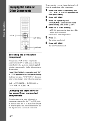
...FUNCTION +/- DVD t TUNER FM t TUNER AM t TV t VCR t AUDIO t ... Changing the input level of the sound from the sound of the other components connected to the AUDIO IN jack on the operation. To prevent this, you press FUNCTION +/-, the mode of the unit or to the TV or VCR... jacks on the component connected. 32US Selecting the connected component You can change the input level from connected components Distortion may occur when listening to a component connected to the TV or VCR jacks on the rear of the system changes in the front panel display, then press or...
...FUNCTION +/- DVD t TUNER FM t TUNER AM t TV t VCR t AUDIO t ... Changing the input level of the sound from the sound of the other components connected to the AUDIO IN jack on the operation. To prevent this, you press FUNCTION +/-, the mode of the unit or to the TV or VCR... jacks on the component connected. 32US Selecting the connected component You can change the input level from connected components Distortion may occur when listening to a component connected to the TV or VCR jacks on the rear of the system changes in the front panel display, then press or...


