
Service Manual
Page 3
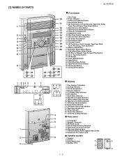
Clock/Timer Button 5. CD Track Down or Fast Reverse, Tape Fast Wind, Tuner Preset Down, Time Down Button 6. Volume Control 15. Tuner (Band) Button 23. Tuning ... Pre-output Jack ■ Speaker system 8 1. CD Repeat Play Indicator 6. Cassette Compartment 9. [3] NAMES OF PARTS 1 2 3 4 5 6 7 8 9 21 23 22 24 1 2 34 5 67 14 15 16 17 1 2 3 XL-HP515 10 11 12 13 14 15 16 17 18 19 20 25 26 27 I Front panel 1. CD Button 22.
Clock/Timer Button 5. CD Track Down or Fast Reverse, Tape Fast Wind, Tuner Preset Down, Time Down Button 6. Volume Control 15. Tuner (Band) Button 23. Tuning ... Pre-output Jack ■ Speaker system 8 1. CD Repeat Play Indicator 6. Cassette Compartment 9. [3] NAMES OF PARTS 1 2 3 4 5 6 7 8 9 21 23 22 24 1 2 34 5 67 14 15 16 17 1 2 3 XL-HP515 10 11 12 13 14 15 16 17 18 19 20 25 26 27 I Front panel 1. CD Button 22.
Service Manual
Page 4
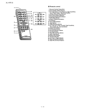
... Button 22 8. Remote Control Transmitter 2. CD Button 23 10. Clock/Timer Button 15. Tape Stop Button 20. Tape Forward Play Button 24. CD Track Down or Fast Reverse, Tape Fast Wind, Tuner Preset Down, Time Down Button 20 4. Video/Auxiliary Button 13. XL-HP515 1 2 3 4 5 6 7 8 9 10 15 16 11 17 12 18 13 19...
... Button 22 8. Remote Control Transmitter 2. CD Button 23 10. Clock/Timer Button 15. Tape Stop Button 20. Tape Forward Play Button 24. CD Track Down or Fast Reverse, Tape Fast Wind, Tuner Preset Down, Time Down Button 20 4. Video/Auxiliary Button 13. XL-HP515 1 2 3 4 5 6 7 8 9 10 15 16 11 17 12 18 13 19...
Service Manual
Page 11
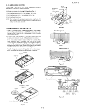
.... How to protect the optical pickup from the static electricity. 2.2. Stop Washer (A1) x1 Optical Pickup CD Mechanism (A3) x2 ø2.6 x5mm XL-HP515 Shaft Gear (A4) x1 (A2) x1 Figure 1 Reduction gear C Front Rear Figure 2 Reduction gear D Up Down Figure 3 CD Disc CD ... Mark 4 (DISC 2) (DISC 4) Figure 4 Tray eject Figure 6 Gear up down board is located at tray No. 1 position, then rotate Reduction gear C clock-wise until Disc tray is covered with conductive aluminium foil or the like to remove CD Disc (See Fig. 2~6) 1. 2. CD MECHANISM SECTION Perform steps 1 to...
.... How to protect the optical pickup from the static electricity. 2.2. Stop Washer (A1) x1 Optical Pickup CD Mechanism (A3) x2 ø2.6 x5mm XL-HP515 Shaft Gear (A4) x1 (A2) x1 Figure 1 Reduction gear C Front Rear Figure 2 Reduction gear D Up Down Figure 3 CD Disc CD ... Mark 4 (DISC 2) (DISC 4) Figure 4 Tray eject Figure 6 Gear up down board is located at tray No. 1 position, then rotate Reduction gear C clock-wise until Disc tray is covered with conductive aluminium foil or the like to remove CD Disc (See Fig. 2~6) 1. 2. CD MECHANISM SECTION Perform steps 1 to...
Service Manual
Page 19
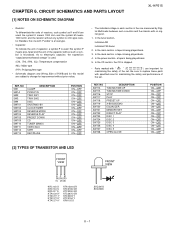
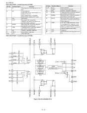
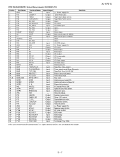
... SW3 SW4 SW701 SW702 SW703 SW704 SW705 SW709 SW710 SW711 SW712 SW713 DESCRIPTION CLAMP PICKUP IN TRAY SW1 TRAY SW2 DISC ON/STAND-BY CLOCK/TIMER REVERSE MODE REVERSE PLAY PRESET DOWN CD TUNER (BAND) VIDEO/AUX TAPE REC/PAUSE POSITION ON-OFF ON-OFF ON-OFF ON-... Y KTA1504 GR KTC3199 GR KTC3200 GR KTC3875 GR KTC3203 Y KTC3194 Y KRA102 S FRONT VIEW SVC347S SVC230C 6 - 1 CIRCUIT SCHEMATICS AND PARTS LAYOUT [1] NOTES ON SCHEMATIC DIAGRAM XL-HP515 • Resistor: To differentiate the units of the set . In the CD section, the CD is stopped. • Parts marked with no signal given. 1. As...
... SW3 SW4 SW701 SW702 SW703 SW704 SW705 SW709 SW710 SW711 SW712 SW713 DESCRIPTION CLAMP PICKUP IN TRAY SW1 TRAY SW2 DISC ON/STAND-BY CLOCK/TIMER REVERSE MODE REVERSE PLAY PRESET DOWN CD TUNER (BAND) VIDEO/AUX TAPE REC/PAUSE POSITION ON-OFF ON-OFF ON-OFF ON-... Y KTA1504 GR KTC3199 GR KTC3200 GR KTC3875 GR KTC3203 Y KTC3194 Y KRA102 S FRONT VIEW SVC347S SVC230C 6 - 1 CIRCUIT SCHEMATICS AND PARTS LAYOUT [1] NOTES ON SCHEMATIC DIAGRAM XL-HP515 • Resistor: To differentiate the units of the set . In the CD section, the CD is stopped. • Parts marked with no signal given. 1. As...
Service Manual
Page 27
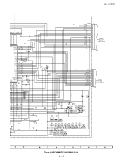
XL-HP515 G6 P_IN AVREF AVDD G6 +B F1 F1 NP NP G1 G2 G3 G4 G5 09 8 7 6 5 4 3 2 1 R795 1.5 C700 1/50 C701 220/10 5 96 97 98 99 ... RD02 RD03 RD04 680 820 1K 1.5K SW701 SW702 SW703 SW704 TUNING TUNING REC/ /TIME /TIME PAUSE UP DOWN SW705 STOP PRESET PLAY UP ON/ CLOCK/ REVERSE REVERSE STANDBY TIMER/ MODE PLAY PRESET DOWN 7 8 9 10 11 12 Figure 6-9 SCHEMATIC DIAGRAM (8/10) 6 - 9
XL-HP515 G6 P_IN AVREF AVDD G6 +B F1 F1 NP NP G1 G2 G3 G4 G5 09 8 7 6 5 4 3 2 1 R795 1.5 C700 1/50 C701 220/10 5 96 97 98 99 ... RD02 RD03 RD04 680 820 1K 1.5K SW701 SW702 SW703 SW704 TUNING TUNING REC/ /TIME /TIME PAUSE UP DOWN SW705 STOP PRESET PLAY UP ON/ CLOCK/ REVERSE REVERSE STANDBY TIMER/ MODE PLAY PRESET DOWN 7 8 9 10 11 12 Figure 6-9 SCHEMATIC DIAGRAM (8/10) 6 - 9
Service Manual
Page 33
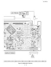
XL-HP515 C703 LED PWB-B3 1 7 R573 1 2 BI707 LED708 12 CNS707 5 16 17 18 19 20 21 FL702 DISPLAY 81 80 28 29 30 31 32 33 ... C707 R562 CNP706B R748 R795 1 2 3 5 4 R564 6 7 R563 C724 R565 SW705 PRESET DOWN SW701 POWER ON/ STAND-BY RD01 SW702 RD04 SW704 REVERSE PLAY RD03 RD02 CLOCK/ TIMER SW703 REVERSE MODE CNP701A 20 18 16 14 12 10 8 6 4 2 21 19 17 15 13 11 9 7 5 3 1 DISPLAY PWB-B1 21 1 FFC701 CNP701B 6-13 11...
XL-HP515 C703 LED PWB-B3 1 7 R573 1 2 BI707 LED708 12 CNS707 5 16 17 18 19 20 21 FL702 DISPLAY 81 80 28 29 30 31 32 33 ... C707 R562 CNP706B R748 R795 1 2 3 5 4 R564 6 7 R563 C724 R565 SW705 PRESET DOWN SW701 POWER ON/ STAND-BY RD01 SW702 RD04 SW704 REVERSE PLAY RD03 RD02 CLOCK/ TIMER SW703 REVERSE MODE CNP701A 20 18 16 14 12 10 8 6 4 2 21 19 17 15 13 11 9 7 5 3 1 DISPLAY PWB-B1 21 1 FFC701 CNP701B 6-13 11...
Service Manual
Page 39
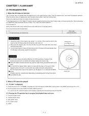
... please replace the cleaner disc. Unauthorized duplicating, broadcasting and renting this section does not operate even after the above step is dirty. FLOWCHART XL-HP515 [1] TROUBLESHOOTING 1. "Track skipping and/or no TOC (Table Of Contents) may not operate when the objective lens of the cleaning fluid...by law. All rights reserved. Cleaner disc 2. When this product is displayed. 1) Check the power to IC1 (LC78648E), the presence of the clock signal (16.9344 MHz) and the status of this happening then drink and / or rinse with the DSP). 2.2. Cleaning fluid CAUTION The ...
... please replace the cleaner disc. Unauthorized duplicating, broadcasting and renting this section does not operate even after the above step is dirty. FLOWCHART XL-HP515 [1] TROUBLESHOOTING 1. "Track skipping and/or no TOC (Table Of Contents) may not operate when the objective lens of the cleaning fluid...by law. All rights reserved. Cleaner disc 2. When this product is displayed. 1) Check the power to IC1 (LC78648E), the presence of the clock signal (16.9344 MHz) and the status of this happening then drink and / or rinse with the DSP). 2.2. Cleaning fluid CAUTION The ...
Service Manual
Page 44
...02 outputs. Controlled by commands from the micro- In this unit, the terminal with asterisk mark (*) is (open when unused. XL-HP515 IC1 VHiLC78648E-1: CD Digital Signal Processor (LC78648E) (2/2) Pin No. 44 45 46 47 48 Terminal Name RCHO RVDD XVSS XOUT XIN... connect to the outside. Built-in Reset RVDD /2 - - Oscillator Oscillator Function Right channel R channel Power supply pin. DAC external clock input pin. Internal signal monitor pin 5. ports and connected to 0V, or set LOW briefly after power is not connected to 0...
...02 outputs. Controlled by commands from the micro- In this unit, the terminal with asterisk mark (*) is (open when unused. XL-HP515 IC1 VHiLC78648E-1: CD Digital Signal Processor (LC78648E) (2/2) Pin No. 44 45 46 47 48 Terminal Name RCHO RVDD XVSS XOUT XIN... connect to the outside. Built-in Reset RVDD /2 - - Oscillator Oscillator Function Right channel R channel Power supply pin. DAC external clock input pin. Internal signal monitor pin 5. ports and connected to 0V, or set LOW briefly after power is not connected to 0...
Service Manual
Page 48
...Volume + equaliser output pin Treble band filter comprising capacitor and resistor connection pin. XL-HP515 IC601 VHiLC75341/-1: Audio Processor (LC75341) Pin No. 1 2 3 4 5 6 7 8 9-12 Terminal Name DI CE VSS LOUT LBASS LTRE LIN LSEL0 L4-1 Function Serial data and clock input pin for analog ground. IC601 VHiLC75341/-1: Audio Processor (LC75341) Pin No. ...181;F to "L". Treble band filter comprising capacitor and resistor connection pin. Chip enable pin. Input selector output pin. Supply pin Serial data and clock input pin for control. Volume + equaliser output pin.
...Volume + equaliser output pin Treble band filter comprising capacitor and resistor connection pin. XL-HP515 IC601 VHiLC75341/-1: Audio Processor (LC75341) Pin No. 1 2 3 4 5 6 7 8 9-12 Terminal Name DI CE VSS LOUT LBASS LTRE LIN LSEL0 L4-1 Function Serial data and clock input pin for analog ground. IC601 VHiLC75341/-1: Audio Processor (LC75341) Pin No. ...181;F to "L". Treble band filter comprising capacitor and resistor connection pin. Chip enable pin. Input selector output pin. Supply pin Serial data and clock input pin for control. Volume + equaliser output pin.
Service Manual
Page 49
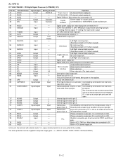
...Output Input Output Output Output Input Input Output Input Function (+) Power supply 5V. -20dB Attenuator. Open. Open. Main clock output 4.19MHz. Data input. CD Data output. Tape Fool Proof A & B SW. Speaker abnormal detect. AC relay control. RDS data..... Tape record bias control. CD WRQ input. GND Open CD DRF detect. (+) Power supply 5V. Analog ground. RDS reset. XL-HP515 8 - 7 Reset Input. CD Clock. Tuner signal meter/Span Selecetor. Power abnormal detect. Remocon input. Tape solenoid control. In this unit, the terminal with asterisk mark...
...Output Input Output Output Output Input Input Output Input Function (+) Power supply 5V. -20dB Attenuator. Open. Open. Main clock output 4.19MHz. Data input. CD Data output. Tape Fool Proof A & B SW. Speaker abnormal detect. AC relay control. RDS data..... Tape record bias control. CD WRQ input. GND Open CD DRF detect. (+) Power supply 5V. Analog ground. RDS reset. XL-HP515 8 - 7 Reset Input. CD Clock. Tuner signal meter/Span Selecetor. Power abnormal detect. Remocon input. Tape solenoid control. In this unit, the terminal with asterisk mark...
Service Manual
Page 59
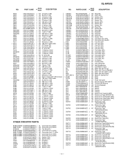
XL-HP515 NO. PARTS CODE PRICE RANK DESCRIPTION R843 R844 R853 R854 R857 R858 R859 R863 R864 R890 R901,902 R903,904 R905,906 R907 R908 R909 ... Type [TRAY SW1] AD Switch,Push Type [TRAY SW2] AF Switch,Push Type [DISC] AC Switch,Key Type [ON/STAND-BY] AC Switch,Key Type [CLOCK/TIMER] AC Switch,Key Type [REVERSE MODE] AC Switch,Key Type [REVERSE PLAY] AC Switch,Key Type [PRESET DOWN] AC Switch,Key Type [CD] AC...
XL-HP515 NO. PARTS CODE PRICE RANK DESCRIPTION R843 R844 R853 R854 R857 R858 R859 R863 R864 R890 R901,902 R903,904 R905,906 R907 R908 R909 ... Type [TRAY SW1] AD Switch,Push Type [TRAY SW2] AF Switch,Push Type [DISC] AC Switch,Key Type [ON/STAND-BY] AC Switch,Key Type [CLOCK/TIMER] AC Switch,Key Type [REVERSE MODE] AC Switch,Key Type [REVERSE PLAY] AC Switch,Key Type [PRESET DOWN] AC Switch,Key Type [CD] AC...


