
Service Manual
Page 3
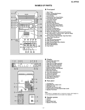
.... Extra Bass/Demo Mode Button 7 12 13. CD or Tape Stop Button 17. CD Button 8 15 16 17 18 19 21. FM Stereo Mode Indicator 7. Timer Recording Indicator 11. CD Pause Indicator 13. Video/Auxiliary (Audio Signal) Input Jacks 6. Speaker Terminals - 3 - Timer/... Indicator 15. s Speaker system 1. Tuning and Time Up Button 7. CD Play Indicator 3. Memory/Set Button 25. Tweeter 2. NAMES OF PARTS XL-HP500 s Front panel 1. CD Eject Buttons 5 11 10. Tape Reverse Mode Select Button 20 24. Bass Reflex Duct 4. Disc Number Indicators 2. ...
.... Extra Bass/Demo Mode Button 7 12 13. CD or Tape Stop Button 17. CD Button 8 15 16 17 18 19 21. FM Stereo Mode Indicator 7. Timer Recording Indicator 11. CD Pause Indicator 13. Video/Auxiliary (Audio Signal) Input Jacks 6. Speaker Terminals - 3 - Timer/... Indicator 15. s Speaker system 1. Tuning and Time Up Button 7. CD Play Indicator 3. Memory/Set Button 25. Tweeter 2. NAMES OF PARTS XL-HP500 s Front panel 1. CD Eject Buttons 5 11 10. Tape Reverse Mode Select Button 20 24. Bass Reflex Duct 4. Disc Number Indicators 2. ...
Service Manual
Page 11
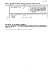
... detection or +B PROTECTION had been detected for the 5th times. Display will only be displayed when error had occurred, it can be displayed instead of Stereo System Error Message Display Contents CD TUNER Error Contents Pickup Mechanism Error. PLL Unlock. 'ER-CD31' 'NO DISC' FM 87.50 MHz Notes PU-IN... Focus Not Match/ IL Time Over. DSP COMMUNICATION ERROR PLL Unlock. (*) CHECKING: If error is condition when irregular process occur on power supply line. - 11 - XL-HP500 Standard Specification of 'ER-CD**' . 'ER-CD**' display will show "S** B**".
... detection or +B PROTECTION had been detected for the 5th times. Display will only be displayed when error had occurred, it can be displayed instead of Stereo System Error Message Display Contents CD TUNER Error Contents Pickup Mechanism Error. PLL Unlock. 'ER-CD31' 'NO DISC' FM 87.50 MHz Notes PU-IN... Focus Not Match/ IL Time Over. DSP COMMUNICATION ERROR PLL Unlock. (*) CHECKING: If error is condition when irregular process occur on power supply line. - 11 - XL-HP500 Standard Specification of 'ER-CD**' . 'ER-CD**' display will show "S** B**".
Service Manual
Page 12
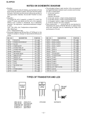
... Y KTC3203 Y KTA1273 Y 2SC1845 F BC E KTC2026 - 12 - In the CD section, the CD is microfarad. In the tuner section, indicates AM indicates FM stereo 2. NO SW4 SW701 SW702 SW703 SW704 SW705 SW706 SW707 SW708 SW712 SW713 SW714 SW715 SW716 SW717 SW718 SW719 DESCRIPTION PICKUP IN POWER ON/STAND-BY... ON-OFF REF. In the deck section, a tape is being played back. 4. REF. In the main section, a tape is being played back. 3. XL-HP500 NOTES ON SCHEMATIC DIAGRAM • Resistor: To differentiate the units of resistors, such symbol as K and M are used: the symbol K means 1000 ohm and...
... Y KTC3203 Y KTA1273 Y 2SC1845 F BC E KTC2026 - 12 - In the CD section, the CD is microfarad. In the tuner section, indicates AM indicates FM stereo 2. NO SW4 SW701 SW702 SW703 SW704 SW705 SW706 SW707 SW708 SW712 SW713 SW714 SW715 SW716 SW717 SW718 SW719 DESCRIPTION PICKUP IN POWER ON/STAND-BY... ON-OFF REF. In the deck section, a tape is being played back. 4. REF. In the main section, a tape is being played back. 3. XL-HP500 NOTES ON SCHEMATIC DIAGRAM • Resistor: To differentiate the units of resistors, such symbol as K and M are used: the symbol K means 1000 ohm and...
Service Manual
Page 14
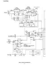
HEAD REC. XL-HP500 CNP302 FM/AM LOOP 1 ANTENNA 2 3 IC303 +B6 +B5 IC301 LA1832S B.P.F BF301 TA7358AP FM FRONT END 1 34 6 9 57 8 FM IF DET. REC/PLAY ERASE HEAD SWITCHING ... FM DET L 14 FM OSC Q302 R 15 VCO FM/AM MO/ST MPXIN FM/AM OUT AM IF 24 23 21 7 18 16 12 20 STEREO AM OSC OUT AM OSC IN AM RF IN AM AM BAND TRACKING COVERAGE T303 T306 +B6 VT X352 4.5 MHZ IC302 CE DI CLK DO...
HEAD REC. XL-HP500 CNP302 FM/AM LOOP 1 ANTENNA 2 3 IC303 +B6 +B5 IC301 LA1832S B.P.F BF301 TA7358AP FM FRONT END 1 34 6 9 57 8 FM IF DET. REC/PLAY ERASE HEAD SWITCHING ... FM DET L 14 FM OSC Q302 R 15 VCO FM/AM MO/ST MPXIN FM/AM OUT AM IF 24 23 21 7 18 16 12 20 STEREO AM OSC OUT AM OSC IN AM RF IN AM AM BAND TRACKING COVERAGE T303 T306 +B6 VT X352 4.5 MHZ IC302 CE DI CLK DO...
Operation Manual
Page 6
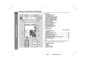
... Reference page 1. Subwoofer Output Socket 28 4. Video/Auxiliary (Audio Signal) Input Sockets 27 9. Tweeter 2. FM Stereo Receiving Indicator 8. AM Loop Aerial Socket 7, 8 8. " Speaker system 1. Speaker Terminals 02/8/6 XL-HP500W(A)1.fm Tape Reverse Mode Indicator 4. Cooling Fan 3. FM Stereo Mode Indicator 7. Span Selector Switch 10 10. Speaker Terminals 7, 8 Note: This product is equipped with...
... Reference page 1. Subwoofer Output Socket 28 4. Video/Auxiliary (Audio Signal) Input Sockets 27 9. Tweeter 2. FM Stereo Receiving Indicator 8. AM Loop Aerial Socket 7, 8 8. " Speaker system 1. Speaker Terminals 02/8/6 XL-HP500W(A)1.fm Tape Reverse Mode Indicator 4. Cooling Fan 3. FM Stereo Mode Indicator 7. Span Selector Switch 10 10. Speaker Terminals 7, 8 Note: This product is equipped with...
Operation Manual
Page 19
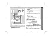
... the desired frequency band (FM or AM). FM stereo receiving indicator " If the FM reception is in stereo. sired station. Note: This product can receive FM stereo/FM monaural and AM monaural broadcasts. E-18 02/8/6 XL-HP500W(A)2.fm " Auto scan tuning will not be played in stereo. Tuning 1 Press the ON/STAND-BY button to...
... the desired frequency band (FM or AM). FM stereo receiving indicator " If the FM reception is in stereo. sired station. Note: This product can receive FM stereo/FM monaural and AM monaural broadcasts. E-18 02/8/6 XL-HP500W(A)2.fm " Auto scan tuning will not be played in stereo. Tuning 1 Press the ON/STAND-BY button to...


