
Service Manual
Page 1
ADJUSTMENTS [1] CD Section 2-1 [2] Test Mode 2-2 [3] Standard Specification Of Stereo System Error Message Display Contents 2-4 CHAPTER 3. CIRCUIT DESCRIPTION [1] Waveforms Of Servo Circuit 5-1 [2] IC Voltage 5-3 CHAPTER 6. ...PWB 6-12 CHAPTER 7. " are subject to change without notice. Be sure to those specified be used . XL-DK225 SERVICE MANUAL No. FLOWCHART [1] Troubleshooting 7-1 CHAPTER 8. CONTENTS PRECAUTIONS FOR USING LEAD-FREE SOLDER CHAPTER 1. SHARP CORPORATION This document has been published to be used for after sales service only. - 1 The contents are...
ADJUSTMENTS [1] CD Section 2-1 [2] Test Mode 2-2 [3] Standard Specification Of Stereo System Error Message Display Contents 2-4 CHAPTER 3. CIRCUIT DESCRIPTION [1] Waveforms Of Servo Circuit 5-1 [2] IC Voltage 5-3 CHAPTER 6. ...PWB 6-12 CHAPTER 7. " are subject to change without notice. Be sure to those specified be used . XL-DK225 SERVICE MANUAL No. FLOWCHART [1] Troubleshooting 7-1 CHAPTER 8. CONTENTS PRECAUTIONS FOR USING LEAD-FREE SOLDER CHAPTER 1. SHARP CORPORATION This document has been published to be used for after sales service only. - 1 The contents are...
Service Manual
Page 2
... during use, file it . Employing lead-free solder "MAIN, POWER, SPEAKER, TRANSIT iPOD, DISPLAY, HEADPHONE, RE-FLASH, VOLUME LED, iPOD, CD MP3 PWB" of lead-free solder. However, since the land may be peeled off the power of the soldering bit may cause damage or accident...lead-free solder, and is attached on and off or the maximum heat-resistance temperature of it with steel wool or fine sandpaper. XL-DK225 AXSMEPeRuLardEr-vMkMiiCocePAePt1U1M55T00aIOnuNaSl FOR USING LEAD-FREE SOLDER 1. Repairing with conventional lead wire solder may be exceeded, remove the bit from the...
... during use, file it . Employing lead-free solder "MAIN, POWER, SPEAKER, TRANSIT iPOD, DISPLAY, HEADPHONE, RE-FLASH, VOLUME LED, iPOD, CD MP3 PWB" of lead-free solder. However, since the land may be peeled off the power of the soldering bit may cause damage or accident...lead-free solder, and is attached on and off or the maximum heat-resistance temperature of it with steel wool or fine sandpaper. XL-DK225 AXSMEPeRuLardEr-vMkMiiCocePAePt1U1M55T00aIOnuNaSl FOR USING LEAD-FREE SOLDER 1. Repairing with conventional lead wire solder may be exceeded, remove the bit from the...
Service Manual
Page 3
...servicing other than that contained in the operating instructions unless you are for use by qualified service personnel only. CHAPTER 1. GENERAL DESCRIPTION XL-DK225 [1] Important Service Safety Precaution CAUTION : "These servicing instructions are qualified to 20 kHz, 10% total harmonic distortion Speakers: ...Subwoofer pre-out (audio signal): 200 mV/10 k ohms at 70 Hz Video/Auxiliary (audio signal): 500 mV/47 k ohms CD player Type Signal readout D/A converter Frequency response Dynamic range 5-disc multi-play compact disc player Non-contact, 3-beam semiconductor laser pickup ...
...servicing other than that contained in the operating instructions unless you are for use by qualified service personnel only. CHAPTER 1. GENERAL DESCRIPTION XL-DK225 [1] Important Service Safety Precaution CAUTION : "These servicing instructions are qualified to 20 kHz, 10% total harmonic distortion Speakers: ...Subwoofer pre-out (audio signal): 200 mV/10 k ohms at 70 Hz Video/Auxiliary (audio signal): 500 mV/47 k ohms CD player Type Signal readout D/A converter Frequency response Dynamic range 5-disc multi-play compact disc player Non-contact, 3-beam semiconductor laser pickup ...
Service Manual
Page 4
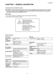
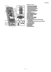
.../WMA Total Indicator 9. FM Stereo Receiving Indicator 12. Disc Play Indicator Rear panel 3 1. Speaker Wire 2 4 1 - 24 XL-DK225 [3] Names Of Parts 10 Front panel 1. Disc or iPod Play or Pause Button 7. Power On/Standby Button 8. CD Button 9. Video/Auxiliary/iPod Button 11. MP3/WMA Folder Indicator 3. Cooling Fan 6 9. Volume Control 13. Disc...
.../WMA Total Indicator 9. FM Stereo Receiving Indicator 12. Disc Play Indicator Rear panel 3 1. Speaker Wire 2 4 1 - 24 XL-DK225 [3] Names Of Parts 10 Front panel 1. Disc or iPod Play or Pause Button 7. Power On/Standby Button 8. CD Button 9. Video/Auxiliary/iPod Button 11. MP3/WMA Folder Indicator 3. Cooling Fan 6 9. Volume Control 13. Disc...
Service Manual
Page 5
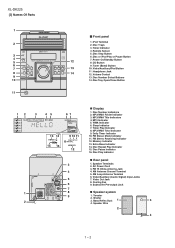
... Stop Button 13. Tuning Up Button 18 19 17. Play Mode Button 6 21. XL-DK225 Remote control 1 1. Volume Up and Down Buttons 9 2 7. iPod Play or Pause Button 16. Folder Button 23. Disc Play or Pause Button 15. CD Track Up or Fast Forward, Tuner Preset Up, 3 Time Up Button 20 21 22... 18. Tuner (Band) Button 10 10. CD Track Down or Fast Reverse, Tuner Preset Down, 4 Time Down Button 23 19. Equalizer Mode Select Button 8 12 5. Remote Control Transmitter 11 2. Extra Bass/Demo ...
... Stop Button 13. Tuning Up Button 18 19 17. Play Mode Button 6 21. XL-DK225 Remote control 1 1. Volume Up and Down Buttons 9 2 7. iPod Play or Pause Button 16. Folder Button 23. Disc Play or Pause Button 15. CD Track Up or Fast Forward, Tuner Preset Up, 3 Time Up Button 20 21 22... 18. Tuner (Band) Button 10 10. CD Track Down or Fast Reverse, Tuner Preset Down, 4 Time Down Button 23 19. Equalizer Mode Select Button 8 12 5. Remote Control Transmitter 11 2. Extra Bass/Demo ...
Service Manual
Page 6
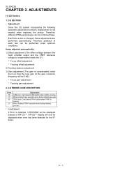
... Explanation CAM error. Therefore, playback of 'ER-CD**'. 'ER-CD**' display will be displayed when error had been detected for the 5th times. 2 - 1 ADJUSTMENTS [1] CD Section 1. CD SECTION • Adjustment Since this CD system incorporates the following automatic adjustment functions, readjustment ...adjustment 2) Tracking balance adjustment 3) Gain adjustment (The gain is moving . When it detect TRAY operation error during initialize process. XL-DK225 CHAPTER 2. Each time a disc is not needed when replacing the pickup. Can't detect TRAY switch when TRAY is detected...
... Explanation CAM error. Therefore, playback of 'ER-CD**'. 'ER-CD**' display will be displayed when error had been detected for the 5th times. 2 - 1 ADJUSTMENTS [1] CD Section 1. CD SECTION • Adjustment Since this CD system incorporates the following automatic adjustment functions, readjustment ...adjustment 2) Tracking balance adjustment 3) Gain adjustment (The gain is moving . When it detect TRAY operation error during initialize process. XL-DK225 CHAPTER 2. Each time a disc is not needed when replacing the pickup. Can't detect TRAY switch when TRAY is detected...
Service Manual
Page 7
... ON > key input. STOP and return to enter the test mode.\ XL-DK225 Step 1 Step 2 Step 3 Step 4 Step 5 CD TE ST OPEN/CLOSE operation is using manual. > key input. Start Auto Adjustment at current pick-up location. Then, press the CD button to Step 1 Hold down the 3 button and 44 button. Reading Sub...
... ON > key input. STOP and return to enter the test mode.\ XL-DK225 Step 1 Step 2 Step 3 Step 4 Step 5 CD TE ST OPEN/CLOSE operation is using manual. > key input. Start Auto Adjustment at current pick-up location. Then, press the CD button to Step 1 Hold down the 3 button and 44 button. Reading Sub...
Service Manual
Page 9
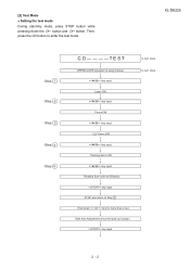
... process 20: TRAY SW Detection NG during normal operation 21: TRAY SW Detection NG during initialize process PLL Unlock. (*) CHECKING: If CD changer mechanism error is ready for the 5th times. Unplug the AC cord and the unit is detected, 'CHECKING' will be display...had occurred, the unit will only be displayed as below. [3] Standard Specification Of Stereo System Error Message Display Contents XL-DK225 CD TUNER Error Contents DISPLAY CD Changer Mechanism Error. 'ER-CD**' (*) Focus Not Match/IL Time Over. 'NO DISC' PLL Unlock. Speaker abnormal detection and +B PROTECTION display...
... process 20: TRAY SW Detection NG during normal operation 21: TRAY SW Detection NG during initialize process PLL Unlock. (*) CHECKING: If CD changer mechanism error is ready for the 5th times. Unplug the AC cord and the unit is detected, 'CHECKING' will be display...had occurred, the unit will only be displayed as below. [3] Standard Specification Of Stereo System Error Message Display Contents XL-DK225 CD TUNER Error Contents DISPLAY CD Changer Mechanism Error. 'ER-CD**' (*) Focus Not Match/IL Time Over. 'NO DISC' PLL Unlock. Speaker abnormal detection and +B PROTECTION display...
Service Manual
Page 10
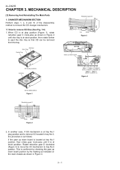
.... MECHANICAL DESCRIPTION [1] Removing And Reinstalling The Main Parts 1. XL-DK255 CHAPTER 3. When CD is at play position and to eject the disc tray so that CD can be removed from the tray. Rotate reduction gear D clockwise (Figure 3) to move the CD mechanism to remove CD Disc (See Fig. 1-4) 1. CD Disc Mark 1 Mark 3 Mark 5 (DISC 1) (DISC 3) (DISC 5) Mark...
.... MECHANICAL DESCRIPTION [1] Removing And Reinstalling The Main Parts 1. XL-DK255 CHAPTER 3. When CD is at play position and to eject the disc tray so that CD can be removed from the tray. Rotate reduction gear D clockwise (Figure 3) to move the CD mechanism to remove CD Disc (See Fig. 1-4) 1. CD Disc Mark 1 Mark 3 Mark 5 (DISC 1) (DISC 3) (DISC 5) Mark...
Service Manual
Page 11
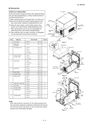
... N3) X 1 14 CD Mechanism 1. Screw A1) X 6 1. Flat Cable C4) X 2 (C3)x1 PULL Front Panel 4 Rear Panel with Speaker PWB 1. Flat Cable E2) X 2 3. Screw H1) X 2 4 1. Screw J4) X 6 10 USB PWB / SUB PWB 1. Screw G1) X 4 3 1. Hook C2) X 2 3. Socket C3) X 3 4. Screw F1) X 3 3 2. Socket F2) X 2 1. Screw D1) X 4 2 2. Screw L1) X 1 5 12 Re-Flash PWB 1. XL-DK255 [2] Disassembly Caution...
... N3) X 1 14 CD Mechanism 1. Screw A1) X 6 1. Flat Cable C4) X 2 (C3)x1 PULL Front Panel 4 Rear Panel with Speaker PWB 1. Flat Cable E2) X 2 3. Screw H1) X 2 4 1. Screw J4) X 6 10 USB PWB / SUB PWB 1. Screw G1) X 4 3 1. Hook C2) X 2 3. Socket C3) X 3 4. Screw F1) X 3 3 2. Socket F2) X 2 1. Screw D1) X 4 2 2. Screw L1) X 1 5 12 Re-Flash PWB 1. XL-DK255 [2] Disassembly Caution...
Service Manual
Page 12
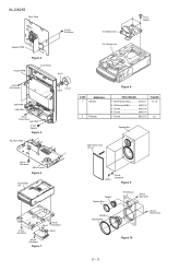
...A2) X 4 3. Screw A3) X 4 4. Screw B1) X 2 FIGURE 9, 10 10 Speaker Box Net Frame Ass'y (A1) x1 (M1)x1 Ø3x10mm Main Chassis Figure 6 CD Changer Unit (P1)x2 Ø3x10mm (N2)x2 (P1)x2 Ø3x10mm (N3)x1 (N1)x3 Ø3x10mm Figure 7 (A2)x4 (A3)x4 Ø4x20mm ...Ø3x14mm (A4)x4 Ø3.5x14mm Figure 10 3 - 3 Screw A4) X 4 1. Net Frame Ass'y A1) X 1 2. XL-DK255 Rear Panel (H1)x2 Ø3x10mm CD Mechanism (P2)x4 Special Speaker PWB Figure 4 Display PWB Front Panel (J2)x1 CD Changer Unit (J4)x6 Ø2.6x10mm SUB PWB USB PWB (K1)x2 Ø2.6x10mm Jack PWB...
...A2) X 4 3. Screw A3) X 4 4. Screw B1) X 2 FIGURE 9, 10 10 Speaker Box Net Frame Ass'y (A1) x1 (M1)x1 Ø3x10mm Main Chassis Figure 6 CD Changer Unit (P1)x2 Ø3x10mm (N2)x2 (P1)x2 Ø3x10mm (N3)x1 (N1)x3 Ø3x10mm Figure 7 (A2)x4 (A3)x4 Ø4x20mm ...Ø3x14mm (A4)x4 Ø3.5x14mm Figure 10 3 - 3 Screw A4) X 4 1. Net Frame Ass'y A1) X 1 2. XL-DK255 Rear Panel (H1)x2 Ø3x10mm CD Mechanism (P2)x4 Special Speaker PWB Figure 4 Display PWB Front Panel (J2)x1 CD Changer Unit (J4)x6 Ø2.6x10mm SUB PWB USB PWB (K1)x2 Ø2.6x10mm Jack PWB...
Service Manual
Page 18
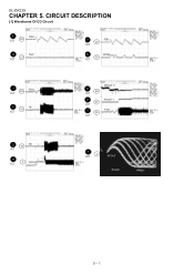
CIRCUIT DESCRIPTION [1] Waveforms Of CD Circuit 1 FDO IC1 22 2 TDO 23 IC1 1 FDO 22 IC1 5 SPDO 25 IC1 1 22 FDO IC1 3 TE 16 IC1 6 28 IC1 PDOUT 0 7 PDOUT 1 27 IC1 1 22 FDO IC1 3 TE 16 IC1 4 IC1 2 RFOUT 4 2 IC1 RFOUT 5 - 1 XL-DK225 CHAPTER 5.
CIRCUIT DESCRIPTION [1] Waveforms Of CD Circuit 1 FDO IC1 22 2 TDO 23 IC1 1 FDO 22 IC1 5 SPDO 25 IC1 1 22 FDO IC1 3 TE 16 IC1 6 28 IC1 PDOUT 0 7 PDOUT 1 27 IC1 1 22 FDO IC1 3 TE 16 IC1 4 IC1 2 RFOUT 4 2 IC1 RFOUT 5 - 1 XL-DK225 CHAPTER 5.
Service Manual
Page 23
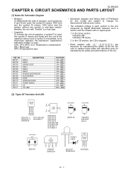
... HSS4148 TOP VIEW 1N4004S DRL204F MA111 TOP VIEW KDS184 FRONT VIEW AC AC 10XB60F S4B05GM FRONT VIEW FRONT VIEW 343VC3F 503BC2E30 1 23 KIA7805A 6 - 1 XL-DK225 CHAPTER 6. As to electrolytic capacitor, the expression "capacitance/ withstand voltage" is used : this model are subject to replace these parts with " ...symbol P means pico-farad and the unit of capacitor, a symbol P is the one with no signal given. 1. In the CD section, the CD is ohm-type resistor. Be sure to change for improvement without any symbol is stopped. • Parts marked with specified ones for...
... HSS4148 TOP VIEW 1N4004S DRL204F MA111 TOP VIEW KDS184 FRONT VIEW AC AC 10XB60F S4B05GM FRONT VIEW FRONT VIEW 343VC3F 503BC2E30 1 23 KIA7805A 6 - 1 XL-DK225 CHAPTER 6. As to electrolytic capacitor, the expression "capacitance/ withstand voltage" is used : this model are subject to replace these parts with " ...symbol P means pico-farad and the unit of capacitor, a symbol P is the one with no signal given. 1. In the CD section, the CD is ohm-type resistor. Be sure to change for improvement without any symbol is stopped. • Parts marked with specified ones for...
Service Manual
Page 34
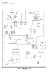
XL-DK225 [4] Charts Of Connecting Wires WH F F C 7 0 5 TUNER PACK 9 FFC301 A ANTENNA 1 FM GND 9 AM F F C 3 0 1 B CNS601 9 8 7 6 5 4 3 2 1 1 9 1 TRANSIT ... B I 8 0 1 BI902 543 21 FAN MOTOR 1 2 3 4 5 C N P 7 0 8 FROM HEADPHONE CNS902 4 3 2 1 SPEAKER PWB-A3 1 2 3 4 CNP902 E JK701 HEADPHONE PWB-B2 R-CH L-CH L-CH L-CH R-CH R-CH SPEAKER TERMINAL S O 9 0 1 TO CD MP3 PWB-D CNP6 F MAIN C N F F C 7 0 2 CNS701 6 5 4 3 2 1 R D G R B L B L G R B L 12 1 17 1 10 C N P 8 0 1 F 1 2 3 4 5 6 7 8 9 10 1 2 3 4 5 6 C N P 8 0 2 7654321 BI701 11 9 7 5 3 1 12 10 8 6 ...
XL-DK225 [4] Charts Of Connecting Wires WH F F C 7 0 5 TUNER PACK 9 FFC301 A ANTENNA 1 FM GND 9 AM F F C 3 0 1 B CNS601 9 8 7 6 5 4 3 2 1 1 9 1 TRANSIT ... B I 8 0 1 BI902 543 21 FAN MOTOR 1 2 3 4 5 C N P 7 0 8 FROM HEADPHONE CNS902 4 3 2 1 SPEAKER PWB-A3 1 2 3 4 CNP902 E JK701 HEADPHONE PWB-B2 R-CH L-CH L-CH L-CH R-CH R-CH SPEAKER TERMINAL S O 9 0 1 TO CD MP3 PWB-D CNP6 F MAIN C N F F C 7 0 2 CNS701 6 5 4 3 2 1 R D G R B L B L G R B L 12 1 17 1 10 C N P 8 0 1 F 1 2 3 4 5 6 7 8 9 10 1 2 3 4 5 6 C N P 8 0 2 7654321 BI701 11 9 7 5 3 1 12 10 8 6 ...
Service Manual
Page 35
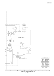
XL-DK225 FROM DISPLAY PWB-B1 CNP702 F F C 7 0 5 12 1 F F C 7 0 2 1 10 11 9 7 5 3 1 12 10 8 6 4 2 CNP3 9 8 7 6 5 4 3 2 1 CNP5 2 4 6 8 10 13579 CNP6 1 1 2 4 6 8 10 1 3 5 7 9 11 C N P 4 T O CD CHANGER MECHANISM UNIT 1 FFC4 T O CD MOTOR PWB 1 2 3 4 5 6 CNS2 1 2 3 4 5 6 C N P 2 WH GR WH GR WH RD FROM MAIN PWB-A1 CNP701B 17 1 17 15 13 11 9 7 5 3 1 16 14 12 10 8 6 4 2 0 2 CNP701A -B1 F F C 7 0 1 CD... MP3 PWB-C CNP1 2 4 6 8 10 12 14 16 1 3 5 7 9 11 13 15 1 16 FFC1 FROM EXTERNAL MICOM DEVICE 1 16 TO CD PICK-UP UNIT 1 2 3 4 5 6 7 8 ...
XL-DK225 FROM DISPLAY PWB-B1 CNP702 F F C 7 0 5 12 1 F F C 7 0 2 1 10 11 9 7 5 3 1 12 10 8 6 4 2 CNP3 9 8 7 6 5 4 3 2 1 CNP5 2 4 6 8 10 13579 CNP6 1 1 2 4 6 8 10 1 3 5 7 9 11 C N P 4 T O CD CHANGER MECHANISM UNIT 1 FFC4 T O CD MOTOR PWB 1 2 3 4 5 6 CNS2 1 2 3 4 5 6 C N P 2 WH GR WH GR WH RD FROM MAIN PWB-A1 CNP701B 17 1 17 15 13 11 9 7 5 3 1 16 14 12 10 8 6 4 2 0 2 CNP701A -B1 F F C 7 0 1 CD... MP3 PWB-C CNP1 2 4 6 8 10 12 14 16 1 3 5 7 9 11 13 15 1 16 FFC1 FROM EXTERNAL MICOM DEVICE 1 16 TO CD PICK-UP UNIT 1 2 3 4 5 6 7 8 ...

Service Manual
Page 51
32 1 2 4 6 8 10 12 14 1 3 5 7 9 11 13 XL-DK225 6 8 10 12 14 16 7 9 11 13 15 Lead-free solder indication Lead-free solder is used in the CD MP3 PWB. Refer to "Precautions for handling lead-free solder" for instructions and precautions. Figure 6-27: WIRING SIDE OF CD MP3 PWB (TOP VIEW) (2/2) 6 - 29
32 1 2 4 6 8 10 12 14 1 3 5 7 9 11 13 XL-DK225 6 8 10 12 14 16 7 9 11 13 15 Lead-free solder indication Lead-free solder is used in the CD MP3 PWB. Refer to "Precautions for handling lead-free solder" for instructions and precautions. Figure 6-27: WIRING SIDE OF CD MP3 PWB (TOP VIEW) (2/2) 6 - 29

Service Manual
Page 52
Figure 6-28: WIRING SIDE OF CD MP3 PWB (BOTTOM VIEW) (1/2) 6 - 30 CD MP3 PWB-D XL-DK225 Lead-free solder indication Lead-free solder is used in the CD MP3 PWB. Refer to "Precautions for handling lead-free solder" for instructions and precautions.
Figure 6-28: WIRING SIDE OF CD MP3 PWB (BOTTOM VIEW) (1/2) 6 - 30 CD MP3 PWB-D XL-DK225 Lead-free solder indication Lead-free solder is used in the CD MP3 PWB. Refer to "Precautions for handling lead-free solder" for instructions and precautions.
Service Manual
Page 54
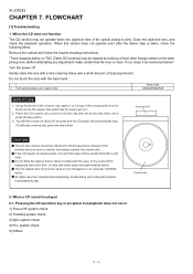
... small amount of the cleaning fluid to the brush on computer CD-ROM drives. The CD cleaner disc must not be caused by law. When a CD cannot be effective for about 20 seconds and the CD player will automatically stop button. XL-DK225 CHAPTER 7. Gently clean the lens with the brush side ...down, then press the play continuously, press the stop . Using the brush in the cleaner cap, apply 1 or 2 drops of isopropyl alcohol. If the CD cleaner brushes become ...
... small amount of the cleaning fluid to the brush on computer CD-ROM drives. The CD cleaner disc must not be caused by law. When a CD cannot be effective for about 20 seconds and the CD player will automatically stop button. XL-DK225 CHAPTER 7. Gently clean the lens with the brush side ...down, then press the play continuously, press the stop . Using the brush in the cleaner cap, apply 1 or 2 drops of isopropyl alcohol. If the CD cleaner brushes become ...

Service Manual
Page 55
... Button without inserting a disc, and try starting the playback operation. 1 FDO IC1 22 2 TDO 23 IC1 XL-DK225 1. No If the level is displayed. Although a CD is inserted and the cover is closed, "NO DISC" is not normal. 1 22 FDO IC1 3 TE 16 IC1 Figure 2 4 2 IC1 RFOUT Figure 3 7 - 2 When a disc is ...
... Button without inserting a disc, and try starting the playback operation. 1 FDO IC1 22 2 TDO 23 IC1 XL-DK225 1. No If the level is displayed. Although a CD is inserted and the cover is closed, "NO DISC" is not normal. 1 22 FDO IC1 3 TE 16 IC1 Figure 2 4 2 IC1 RFOUT Figure 3 7 - 2 When a disc is ...
Service Manual
Page 58
... COILS [6] CRYSTALS / VIBRATORS [7] CAPACITORS [8] RESISTORS [9] OTHER CIRCUITRY PARTS [10] CABINET PARTS / CD MECHANISM PARTS [11] SPEAKER BOX PARTS [12] ACCESSORIES / PACKING PARTS [13] P.W.B. " are ... only. The contents are important for maintaining the safety and performance of the set . SHARP CORPORATION This document has been published to replace these parts with " ! ASSEMBLY (Not ... ones for maintaining the safety of XL-DK225 (main unit) and CP-DK225 (speaker system). XL-DK225 PARTS GUIDE MICRO COMPONENT SYSTEM MODEL XL-DK225 XL-DK225 Micro Component System consisting of the ...
... COILS [6] CRYSTALS / VIBRATORS [7] CAPACITORS [8] RESISTORS [9] OTHER CIRCUITRY PARTS [10] CABINET PARTS / CD MECHANISM PARTS [11] SPEAKER BOX PARTS [12] ACCESSORIES / PACKING PARTS [13] P.W.B. " are ... only. The contents are important for maintaining the safety and performance of the set . SHARP CORPORATION This document has been published to replace these parts with " ! ASSEMBLY (Not ... ones for maintaining the safety of XL-DK225 (main unit) and CP-DK225 (speaker system). XL-DK225 PARTS GUIDE MICRO COMPONENT SYSTEM MODEL XL-DK225 XL-DK225 Micro Component System consisting of the ...

