Service Manual
Page 1
.../EXPLODED VIEW PACKING OF THE SET (FOR U.S.A. ONLY) SHARP CORPORATION - 1 - The contents are subject to be used for after sales service only. MODEL XL-1700C XL-1700C Compact Audio System consisting of XL-1700C (main unit) and CP-XL1700U (speaker system). • In the interests of XL-1700 (main unit) and CP-XL1700U (speaker system). CONTENTS...
.../EXPLODED VIEW PACKING OF THE SET (FOR U.S.A. ONLY) SHARP CORPORATION - 1 - The contents are subject to be used for after sales service only. MODEL XL-1700C XL-1700C Compact Audio System consisting of XL-1700C (main unit) and CP-XL1700U (speaker system). • In the interests of XL-1700 (main unit) and CP-XL1700U (speaker system). CONTENTS...

Service Manual
Page 2
XL-1700/1700C FOR A COMPLETE DESCRIPTION OF THE OPERATION OF THIS UNIT, PLEASE REFER ... ohms) CD digital output (optical) Subwoofer (Audio signal): 500 mV/47 k ohms Video/Auxiliary (audio signal): 500 mV/47 k ohms s Amplifier XL-1700C Output power Output terminals Input terminals RMS: 20 W (10 W + 10 W) (10 % T.H.D.) Speakers: 8 ohms Headphones: 16 - 50... pickup 1-bit D/A converter 20 - 20,000 Hz 90 dB (1 kHz) s Amplifier Output power Output terminals Input terminals XL-1700 8 watts minimum RMS per volt, or higher, sensitivity to measure the AC voltage drop across the resistor (See diagram)....
XL-1700/1700C FOR A COMPLETE DESCRIPTION OF THE OPERATION OF THIS UNIT, PLEASE REFER ... ohms) CD digital output (optical) Subwoofer (Audio signal): 500 mV/47 k ohms Video/Auxiliary (audio signal): 500 mV/47 k ohms s Amplifier XL-1700C Output power Output terminals Input terminals RMS: 20 W (10 W + 10 W) (10 % T.H.D.) Speakers: 8 ohms Headphones: 16 - 50... pickup 1-bit D/A converter 20 - 20,000 Hz 90 dB (1 kHz) s Amplifier Output power Output terminals Input terminals XL-1700 8 watts minimum RMS per volt, or higher, sensitivity to measure the AC voltage drop across the resistor (See diagram)....
Service Manual
Page 3
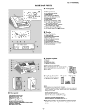
... 2 5 3 6 7 4 1 23 4 6 7 NAMES OF PARTS s Front panel 11 1. CD Stop, Tuning Down Button 9. Speaker Terminals 9. Bass/Treble Selector Button 6. CD Play or Pause, Tuning Up Button XL-1700/1700C 5 8 s Display 1. FM Stereo Receiving Indicator 9. Video/Auxiliary (Audio Signal) Input Jacks 8. AC Power Input Jack s Speaker system 1. Placing the speaker system: Left speaker There...
... 2 5 3 6 7 4 1 23 4 6 7 NAMES OF PARTS s Front panel 11 1. CD Stop, Tuning Down Button 9. Speaker Terminals 9. Bass/Treble Selector Button 6. CD Play or Pause, Tuning Up Button XL-1700/1700C 5 8 s Display 1. FM Stereo Receiving Indicator 9. Video/Auxiliary (Audio Signal) Input Jacks 8. AC Power Input Jack s Speaker system 1. Placing the speaker system: Left speaker There...

Service Manual
Page 4
.... Bass Up and Down Buttons 27. Power Button 3. CD Open/Close Button 17. CD Play Button 21. Dimmer Button 9. Volume Up and Down Buttons 11. XL-1700/1700C 1 2 3 4 5 6 7 8 9 10 11 12 13 17 18 21 14 15 19 22 16 20 23 24 25 26 27 s Remote control 1. Video/Auxiliary Button 12...
.... Bass Up and Down Buttons 27. Power Button 3. CD Open/Close Button 17. CD Play Button 21. Dimmer Button 9. Volume Up and Down Buttons 11. XL-1700/1700C 1 2 3 4 5 6 7 8 9 10 11 12 13 17 18 21 14 15 19 22 16 20 23 24 25 26 27 s Remote control 1. Video/Auxiliary Button 12...
Service Manual
Page 5
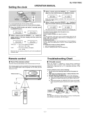
... plug in memory including clock, timer settings, tuner preset, and CD program. - 5 - Note: The time will appear for about 5 seconds. Setting the clock OPERATION MANUAL XL-1700/1700C 3 Within 1 minute, press the PRESET ( or ) button to the stand-by mode. The time display will flash at the push of the remote control...
... plug in memory including clock, timer settings, tuner preset, and CD program. - 5 - Note: The time will appear for about 5 seconds. Setting the clock OPERATION MANUAL XL-1700/1700C 3 Within 1 minute, press the PRESET ( or ) button to the stand-by mode. The time display will flash at the push of the remote control...

Service Manual
Page 7
... integrated circuits and other circuits when servicing. (A1) x2 ø3 x10mm (B1) x1 ø3 x10mm (B1) x1 ø3 x6mm Top Cabinet (C2) x4 ø3 x10mm XL-1700/1700C (B1) x1 ø3 x10mm Cover, Rear Panel STEP REMOVAL PROCEDURE FIGURE 1 Top Cabinet 1. Hook N1) x3 8-3 Note: After removing the connector for the optical...
... integrated circuits and other circuits when servicing. (A1) x2 ø3 x10mm (B1) x1 ø3 x10mm (B1) x1 ø3 x6mm Top Cabinet (C2) x4 ø3 x10mm XL-1700/1700C (B1) x1 ø3 x10mm Cover, Rear Panel STEP REMOVAL PROCEDURE FIGURE 1 Top Cabinet 1. Hook N1) x3 8-3 Note: After removing the connector for the optical...

Service Manual
Page 9
... Shaft (A3) x1 Gear (A5) x1 Stop Washer (A4) x1 Pickup unit Figure 9-2 - 9 - Remove the hooks (A2) x 3 pcs., to remove the gear box.(See page 7,8) 1. XL-1700/1700C REMOVING AND REINSTALLING THE MAIN PARTS How to remove the CD lid (See Fig. 9-1.) Perform steps 1 to 13 of the disassembly method to remove...
... Shaft (A3) x1 Gear (A5) x1 Stop Washer (A4) x1 Pickup unit Figure 9-2 - 9 - Remove the hooks (A2) x 3 pcs., to remove the gear box.(See page 7,8) 1. XL-1700/1700C REMOVING AND REINSTALLING THE MAIN PARTS How to remove the CD lid (See Fig. 9-1.) Perform steps 1 to 13 of the disassembly method to remove...
Service Manual
Page 10
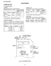
..., 40 kHz dev., FM modulated Frequency Display 87.5 MHz 108 MHz 87.5 MHz 108 MHz Check Point 2.2 V ± 0.7 V 7.3 V ± 1.0 V Instrument Connection TP301 TP301 Preset No. XL-1700/1700C TUNER SECTION ADJUSTMENT fL: Low-range frequency fH: High-range frequency • AM IF/RF Signal generator: 400 Hz, 30%, AM modulated • FM...
..., 40 kHz dev., FM modulated Frequency Display 87.5 MHz 108 MHz 87.5 MHz 108 MHz Check Point 2.2 V ± 0.7 V 7.3 V ± 1.0 V Instrument Connection TP301 TP301 Preset No. XL-1700/1700C TUNER SECTION ADJUSTMENT fL: Low-range frequency fH: High-range frequency • AM IF/RF Signal generator: 400 Hz, 30%, AM modulated • FM...
Service Manual
Page 11
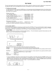
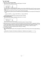
... Test Mode] 1. Then CD initialization operation flow proceeds up Press the following buttons in case of pickup to the inner periphery is invalid. TEST MODE XL-1700/1700C The test mode applied to this microcomputer has three modes, namely the ordinary test mode for adjustment or measurement, the aging test mode, and...
... Test Mode] 1. Then CD initialization operation flow proceeds up Press the following buttons in case of pickup to the inner periphery is invalid. TEST MODE XL-1700/1700C The test mode applied to this microcomputer has three modes, namely the ordinary test mode for adjustment or measurement, the aging test mode, and...

Service Manual
Page 12
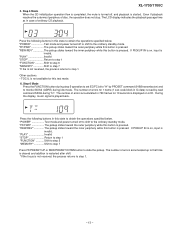
...shift to step 5 3. "REW/REV The pickup slides toward the outer periphery while this button is pressed. If PICKUP IN is on , input is pressed. XL-1700/1700C 2. "FF/FWD The pickup slides toward the inner periphery while this button is invalid. "PLAY Shift to step 3 "STOP Return to step 1 "...inner periphery while this case. If PICKUP IN is on , input is pressed. "STOP Return to step 1 "FUNCTION Shift to step 5 *If the focus is executed. "PLAY Shift to step 5 "STOP Return to step 1 "FUNCTION Shift to step 5 *If the focus is not received, the process returns to step 4 ...
...shift to step 5 3. "REW/REV The pickup slides toward the outer periphery while this button is pressed. If PICKUP IN is on , input is pressed. XL-1700/1700C 2. "FF/FWD The pickup slides toward the inner periphery while this button is invalid. "PLAY Shift to step 3 "STOP Return to step 1 "...inner periphery while this case. If PICKUP IN is on , input is pressed. "STOP Return to step 1 "FUNCTION Shift to step 5 *If the focus is executed. "PLAY Shift to step 5 "STOP Return to step 1 "FUNCTION Shift to step 5 *If the focus is not received, the process returns to step 4 ...
Service Manual
Page 13
... shift. *If the focus is started. Step 6 Mode Press the FUNCTION button during step 5 operation to set EC/FC bit to the ordinary standby mode. XL-1700/1700C 5. The number of errors accumulated up to slide the pickup.
... shift. *If the focus is started. Step 6 Mode Press the FUNCTION button during step 5 operation to set EC/FC bit to the ordinary standby mode. XL-1700/1700C 5. The number of errors accumulated up to slide the pickup.

Service Manual
Page 14
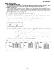
... read by read command SRC2 (2) are displayed in hexadecimal numbers. d) "TG" is shifted to (e). After waiting 2 seconds, operation is displayed on the left of LCD. XL-1700/1700C 7. After waiting 2 seconds, operation is transmitted to the ordinary standby mode. FTBAST command (D486) is shifted to (g). "POWER Test mode and power turned off...
... read by read command SRC2 (2) are displayed in hexadecimal numbers. d) "TG" is shifted to (e). After waiting 2 seconds, operation is displayed on the left of LCD. XL-1700/1700C 7. After waiting 2 seconds, operation is transmitted to the ordinary standby mode. FTBAST command (D486) is shifted to (g). "POWER Test mode and power turned off...
Service Manual
Page 15
... ended; Preset frequencies for judging memory error at initial setting and to protect the memory of tuner (radio) test mode The tuner test mode is executed in the preset memory CH. The operations of test mode are not required to discard the content of destination specified by SPAN switching operation) when... 29 30 BAND FM MONO FM FM106.00 MHz FM 90.00 MHz FM 98.00 MHz FM108.00 MHz FM 87.50 MHz - 15 - XL-1700/1700C 3. When adjusting the tuner section in the memory to be sure to write "0000" or "1111" bits in the production line, adjusting personnel are...
... ended; Preset frequencies for judging memory error at initial setting and to protect the memory of tuner (radio) test mode The tuner test mode is executed in the preset memory CH. The operations of test mode are not required to discard the content of destination specified by SPAN switching operation) when... 29 30 BAND FM MONO FM FM106.00 MHz FM 90.00 MHz FM 98.00 MHz FM108.00 MHz FM 87.50 MHz - 15 - XL-1700/1700C 3. When adjusting the tuner section in the memory to be sure to write "0000" or "1111" bits in the production line, adjusting personnel are...
Service Manual
Page 16
... ordinary operation except test mode setting. (2) Unlike the ordinary state, the volume is controlled with the volume UP/DOWN button in , the fade-out is executed at a rate of fade-in accordance with the following three steps. ∞ Volume- (STEP 0) Volume-14 dB (STEP 23) Volume-0 (STEP 30) (3) ... in the test mode are lighted. The fade-in (when playback is started) is executed at a rate of fade-out, the power is turned off (after WAIT 1 sec), and the mode is counted as below. XL-1700/1700C 4. After completion of one step for 1 sec. Set the current time and ...
... ordinary operation except test mode setting. (2) Unlike the ordinary state, the volume is controlled with the volume UP/DOWN button in , the fade-out is executed at a rate of fade-in accordance with the following three steps. ∞ Volume- (STEP 0) Volume-14 dB (STEP 23) Volume-0 (STEP 30) (3) ... in the test mode are lighted. The fade-in (when playback is started) is executed at a rate of fade-out, the power is turned off (after WAIT 1 sec), and the mode is counted as below. XL-1700/1700C 4. After completion of one step for 1 sec. Set the current time and ...

Service Manual
Page 17
... middle of buttons to repeat counting. If the result is OK, OK is checked whether the "POWER" button was not pressed, an error is displayed. 7. XL-1700/1700C This test mode is returned to 0 to be pressed is checked. if the count is over 59999, display is intended to the standby mode...
... middle of buttons to repeat counting. If the result is OK, OK is checked whether the "POWER" button was not pressed, an error is displayed. 7. XL-1700/1700C This test mode is returned to 0 to be pressed is checked. if the count is over 59999, display is intended to the standby mode...

Service Manual
Page 18
... set . As to change for improvement without prior notice. • The indicated voltage in each section is stopped. • Parts marked with no signal given. 1. XL-1700/1700C NOTES ON SCHEMATIC DIAGRAM • Resistor: To differentiate the units of resistors, such symbol as K and M are important for maintaining the safety and performance...
... set . As to change for improvement without prior notice. • The indicated voltage in each section is stopped. • Parts marked with no signal given. 1. XL-1700/1700C NOTES ON SCHEMATIC DIAGRAM • Resistor: To differentiate the units of resistors, such symbol as K and M are important for maintaining the safety and performance...
Service Manual
Page 19
... 13 12 IF REQ IF IN MO/ST FM VDD MUTE FM IN FM AM IN DO PD AIN CL DI CE 1 3456 7 8 9 10 11 XL-1700/1700C TUNER PWB SD FM ST DO CL DI CE A_12V TUN_L TUN_R D_GND A_GND TO MAIN PWB 11 10 9 8 7 6 5 4 3 2 1 CNS301 IC302 LC72131 PLL(TUNER...
... 13 12 IF REQ IF IN MO/ST FM VDD MUTE FM IN FM AM IN DO PD AIN CL DI CE 1 3456 7 8 9 10 11 XL-1700/1700C TUNER PWB SD FM ST DO CL DI CE A_12V TUN_L TUN_R D_GND A_GND TO MAIN PWB 11 10 9 8 7 6 5 4 3 2 1 CNS301 IC302 LC72131 PLL(TUNER...

Service Manual
Page 20
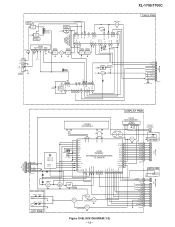
... 1 2 CD_R 3 A_GND CNP803 CD_L 1 2 CD_R 3 A CD PICKUP UN FOCUS COIL +B5 SWITCHING Q801 E F B A TRACKING COIL LD MON C 1/2V +B6 5V Figure 20 BLOCK DIAGRAM (2/3) - 20 - XL-1700/1700C CD PWB FROM DISPLAY PWB 10 9 8 7 6 5 4 3 2 1 CNP704 CD_STB CD_RES CCE BUCK BUS3 BUS2 BUS1 BUS0 PU_IN GVSW FROM TUNER PWB CNP301 11 10 9 8 7 6 5 4 3 2 +B4...
... 1 2 CD_R 3 A_GND CNP803 CD_L 1 2 CD_R 3 A CD PICKUP UN FOCUS COIL +B5 SWITCHING Q801 E F B A TRACKING COIL LD MON C 1/2V +B6 5V Figure 20 BLOCK DIAGRAM (2/3) - 20 - XL-1700/1700C CD PWB FROM DISPLAY PWB 10 9 8 7 6 5 4 3 2 1 CNP704 CD_STB CD_RES CCE BUCK BUS3 BUS2 BUS1 BUS0 PU_IN GVSW FROM TUNER PWB CNP301 11 10 9 8 7 6 5 4 3 2 +B4...

Service Manual
Page 21
... FROM DISPLAY PWB AC 120V,60Hz T681 POWER TRANSFORMER (SUB) SO651 AC INPUT SOCKET AC120V,30Hz AC POWER SUPPLY CORD Figure 21 BLOCK DIAGRAM (3/3) - 21 - XL-1700/1700C D_GND A_12V TUN L A_GND TUN R CE DI CL DO FM ST SD D_GND P_MUTE CD +B SURROUND M PWB 5 4 3 2 1 +B4 CNP803 CD_L 1 2 CD_R 3 A_GND UP UNIT...
... FROM DISPLAY PWB AC 120V,60Hz T681 POWER TRANSFORMER (SUB) SO651 AC INPUT SOCKET AC120V,30Hz AC POWER SUPPLY CORD Figure 21 BLOCK DIAGRAM (3/3) - 21 - XL-1700/1700C D_GND A_12V TUN L A_GND TUN R CE DI CL DO FM ST SD D_GND P_MUTE CD +B SURROUND M PWB 5 4 3 2 1 +B4 CNP803 CD_L 1 2 CD_R 3 A_GND UP UNIT...

Service Manual
Page 22
... SD OUT 7 8 5V STEREO R353 FM DET 270 2.9V MPX VCO C367 1/50 R350 2.7K X351 2 3V456kHz C366 0.001 D301 1N4148 D302 1N4148 B C329 0.022 A XL-1700/1700C Figure 22 SCHEMATIC DIAGRAM (1/8) - 22 - 6 5 4 3 2 1 • NOTES ON SCHEMATIC DIAGRAM can be found on page 18.
... SD OUT 7 8 5V STEREO R353 FM DET 270 2.9V MPX VCO C367 1/50 R350 2.7K X351 2 3V456kHz C366 0.001 D301 1N4148 D302 1N4148 B C329 0.022 A XL-1700/1700C Figure 22 SCHEMATIC DIAGRAM (1/8) - 22 - 6 5 4 3 2 1 • NOTES ON SCHEMATIC DIAGRAM can be found on page 18.