
Service Manual
Page 1
... sales service only. The contents are important for maintaining the safety of the set . TROUBLESHOOTING TABLE [1] TROUBLESHOOTING TABLE 4-1 CHAPTER 5. TopPage SUPPLEMENT ATTACHED LC-52D43U SERVICE MANUAL No. S87P2LC52D43U LCD COLOR TELEVISION MODEL LC-52D43U In the interests of user-safety (Required by safety regulations in some countries) the set should be restored to its original condition...
... sales service only. The contents are important for maintaining the safety of the set . TROUBLESHOOTING TABLE [1] TROUBLESHOOTING TABLE 4-1 CHAPTER 5. TopPage SUPPLEMENT ATTACHED LC-52D43U SERVICE MANUAL No. S87P2LC52D43U LCD COLOR TELEVISION MODEL LC-52D43U In the interests of user-safety (Required by safety regulations in some countries) the set should be restored to its original condition...

Service Manual
Page 2
...LC-32D42U/37D42U (Base Model) LC-52D43U DUNTKD909FM02 DUNTKD910FM02 DUNTKD999FM04 DUNTKD862FM04 RDENCA198WJQZ DUNTKD909FM02 DUNTKD910FM02 DUNTKD935FM02 DUNTKD862FM07 RDENCA184WJQZ Remark No Change No Change Change Change Unit Replacement Item LCD PANEL (NOTE: THE PARTS HERE SHOWN ARE SUPPLIED AS AN ASSEMBLY BUT NOT INDEPENDENTLY.) 32" LCD Panel R1LK315T3LZ4BX Delete 37" LCD Panel R1LK370T3LZ5BW Delete 52" LCD...1Q QJAKFA046WJZZ QJAKEA073WJZZ - LC-52D43U LOCU52DT4L3UINE AND MODIFIED PARTS LIST Service Manual OUTLINE This Service Manual covers the differences from LC-32/37D42U. Change...
...LC-32D42U/37D42U (Base Model) LC-52D43U DUNTKD909FM02 DUNTKD910FM02 DUNTKD999FM04 DUNTKD862FM04 RDENCA198WJQZ DUNTKD909FM02 DUNTKD910FM02 DUNTKD935FM02 DUNTKD862FM07 RDENCA184WJQZ Remark No Change No Change Change Change Unit Replacement Item LCD PANEL (NOTE: THE PARTS HERE SHOWN ARE SUPPLIED AS AN ASSEMBLY BUT NOT INDEPENDENTLY.) 32" LCD Panel R1LK315T3LZ4BX Delete 37" LCD Panel R1LK370T3LZ5BW Delete 52" LCD...1Q QJAKFA046WJZZ QJAKEA073WJZZ - LC-52D43U LOCU52DT4L3UINE AND MODIFIED PARTS LIST Service Manual OUTLINE This Service Manual covers the differences from LC-32/37D42U. Change...
Service Manual
Page 5
... that hardware is excessive and indicates a potential shock hazard which have special safety-related characteristics. LSCA52FD4E3UTY PRECAUTION Service Manual LC-52D43U IMPORTANT SERVICE SAFETY PRECAUTION Service work should be attempted. 2. Inspect all safety checks and the servicing guidelines which ...SAFETY NOTICE Many electrical and mechanical parts in the original circuit. For continued protection, replacement parts must be used in LCD color television have these checks.) Any reading of a substitute replacement parts which follow: „WARNING 1. electrical components...
... that hardware is excessive and indicates a potential shock hazard which have special safety-related characteristics. LSCA52FD4E3UTY PRECAUTION Service Manual LC-52D43U IMPORTANT SERVICE SAFETY PRECAUTION Service work should be attempted. 2. Inspect all safety checks and the servicing guidelines which ...SAFETY NOTICE Many electrical and mechanical parts in the original circuit. For continued protection, replacement parts must be used in LCD color television have these checks.) Any reading of a substitute replacement parts which follow: „WARNING 1. electrical components...

Service Manual
Page 8
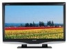
LC-52D43U [2] OPERATION MANUAL Part names TV (Front) NOTE *OPC: Optical Picture Control. **TV status indicator. TV (Rear/Top) HDMI terminal (INPUT 4) HDMI terminal (INPUT 5) PC IN terminals (INPUT 6) Antenna/Cable in AUDIO terminals (INPUT 5) DIGITAL AUDIO OUTPUT terminal INPUT 3 terminals Remote control sensor OPC sensor* OPC indicator** SLEEP indicator** POWER indicator** Channel buttons (CH / ) Volume buttons (VOL / ) INPUT button POWER button INPUT 1 terminals INPUT 2 terminals AUDIO OUTPUT terminals AC INPUT terminal 1 - 2
LC-52D43U [2] OPERATION MANUAL Part names TV (Front) NOTE *OPC: Optical Picture Control. **TV status indicator. TV (Rear/Top) HDMI terminal (INPUT 4) HDMI terminal (INPUT 5) PC IN terminals (INPUT 6) Antenna/Cable in AUDIO terminals (INPUT 5) DIGITAL AUDIO OUTPUT terminal INPUT 3 terminals Remote control sensor OPC sensor* OPC indicator** SLEEP indicator** POWER indicator** Channel buttons (CH / ) Volume buttons (VOL / ) INPUT button POWER button INPUT 1 terminals INPUT 2 terminals AUDIO OUTPUT terminals AC INPUT terminal 1 - 2

Service Manual
Page 15
Remove the 18 lock screws 4 and detach the Rear Cabinet. 4 SD Card Cover 1 3 3 2 2 Stand Rear Cabinet LC-52D43U 2 - 1 Remove the 5 lock screws 3 . 4. Detach the SD Card Cover 1 . 2. Remove the 4 lock screws 2 and detach the Stand. 3. REMOVING OF MAJOR PARSTeSrvice Manual [1] REMOVING OF MAJOR PARTS 1. LCC5H2DA43PU TER 2.
Remove the 18 lock screws 4 and detach the Rear Cabinet. 4 SD Card Cover 1 3 3 2 2 Stand Rear Cabinet LC-52D43U 2 - 1 Remove the 5 lock screws 3 . 4. Detach the SD Card Cover 1 . 2. Remove the 4 lock screws 2 and detach the Stand. 3. REMOVING OF MAJOR PARSTeSrvice Manual [1] REMOVING OF MAJOR PARTS 1. LCC5H2DA43PU TER 2.

Service Manual
Page 20
....) (WBI50800) [Adjustment value] MG5G**** MG5B**** • As per the "standard set" submitted by Engineering Department "LC-52D43U" Teaching set . 2 Automatic adjust- [Command] [Adjustment procedure] ment execution Process mode 1) Using the remote controller, transmit the ..."monitor adjustment process" code. ADJUSTMENT Service Manual [1] ADJUSTMENT PROCEDURE The adjustment values are set at 920 * Initial R, G and B settings at points 1 thru 5: Corrected G setting at the factory before shipping. LC-52D43U LCC5H2DA43PU TER 3. KRSW0001 2) Set the 6th point...
....) (WBI50800) [Adjustment value] MG5G**** MG5B**** • As per the "standard set" submitted by Engineering Department "LC-52D43U" Teaching set . 2 Automatic adjust- [Command] [Adjustment procedure] ment execution Process mode 1) Using the remote controller, transmit the ..."monitor adjustment process" code. ADJUSTMENT Service Manual [1] ADJUSTMENT PROCEDURE The adjustment values are set at 920 * Initial R, G and B settings at points 1 thru 5: Corrected G setting at the factory before shipping. LC-52D43U LCC5H2DA43PU TER 3. KRSW0001 2) Set the 6th point...

Service Manual
Page 26
...to pins 3 and 5 of IC2701(STEREO_AMP) normal? NO Check IC1404 and peripheral circuits. LC-52D43U LCC5H2DA43PU TER 4. YES Is audio input from pins 38 and 39 of IC2701. (MUTE circuits...IC1404 normal? YES Is audio output from the tuner (TU1101_Pin15) normal? TROUBLESHOOTING TABLEService Manual [1] TROUBLESHOOTING TABLE No audio output during UHF/VHF reception Is SIF output from ... speakers. NO Check the circuits between pins 29 and 30 of IC1401 and pins 51 and 52 of IC1401 (SIF Demodulator) normal? YES Check the connector (P2703) of IC1408 (Buffer_AMP)...
...to pins 3 and 5 of IC2701(STEREO_AMP) normal? NO Check IC1404 and peripheral circuits. LC-52D43U LCC5H2DA43PU TER 4. YES Is audio input from pins 38 and 39 of IC2701. (MUTE circuits...IC1404 normal? YES Is audio output from the tuner (TU1101_Pin15) normal? TROUBLESHOOTING TABLEService Manual [1] TROUBLESHOOTING TABLE No audio output during UHF/VHF reception Is SIF output from ... speakers. NO Check the circuits between pins 29 and 30 of IC1401 and pins 51 and 52 of IC1401 (SIF Demodulator) normal? YES Check the connector (P2703) of IC1408 (Buffer_AMP)...

Service Manual
Page 38
PRINTED WIRING BOARD Service Manual [1] AV TERMINAL UNIT PRINTED WIRING BOARD AV TERMINAL Unit (Side-A) J I H G F E D C B A 1 2 3 4 5 6 6 - 1 7 8 9 10 LC-52D43U LCC5H2DA43PU TER 6.
PRINTED WIRING BOARD Service Manual [1] AV TERMINAL UNIT PRINTED WIRING BOARD AV TERMINAL Unit (Side-A) J I H G F E D C B A 1 2 3 4 5 6 6 - 1 7 8 9 10 LC-52D43U LCC5H2DA43PU TER 6.

Service Manual
Page 41
... noted. (K= ± 10%, F= ± 1%, D= ± 0.5%) 3) All resistors are measured with a 20k ohm/V tester. 2. BE SURE TO REPLACE THESE PARTS WITH SPECIFIED ONES FOR MAIN- Service Manual LC-52D43U 7 - 1 INDICATION OF RESISTOR & CAPACITOR: RESISTOR 1) The unit of AC 120V. TAINING THE SAFETY AND PERFORMANCE OF THE SET. SCHEMATIC DIAGRAM [1] DESCRIPTION OF SCHEMATIC DIAGRAM 1. LCC5H2DA43PU...
... noted. (K= ± 10%, F= ± 1%, D= ± 0.5%) 3) All resistors are measured with a 20k ohm/V tester. 2. BE SURE TO REPLACE THESE PARTS WITH SPECIFIED ONES FOR MAIN- Service Manual LC-52D43U 7 - 1 INDICATION OF RESISTOR & CAPACITOR: RESISTOR 1) The unit of AC 120V. TAINING THE SAFETY AND PERFORMANCE OF THE SET. SCHEMATIC DIAGRAM [1] DESCRIPTION OF SCHEMATIC DIAGRAM 1. LCC5H2DA43PU...

Service Manual
Page 99
...safety and performance of user-safety (Required by safety regulations in the LCD module are subject to change without notice. This document has been published to the LC-52D43U (S87P2LC52D43U) Service Manual. Be sure to those specified should be restored to its original condition... parts with " " are important for maintaining the safety of the set should be used . TopPage LC-52D43U SERVICE MANUAL No. S07V9LC52D43U SUPPLEMENT LCD COLOR TELEVISION MODEL LC-52D43U In the interests of the set. Parts marked with specified ones for after sales service only. The contents...
...safety and performance of user-safety (Required by safety regulations in the LCD module are subject to change without notice. This document has been published to the LC-52D43U (S87P2LC52D43U) Service Manual. Be sure to those specified should be restored to its original condition... parts with " " are important for maintaining the safety of the set should be used . TopPage LC-52D43U SERVICE MANUAL No. S07V9LC52D43U SUPPLEMENT LCD COLOR TELEVISION MODEL LC-52D43U In the interests of the set. Parts marked with specified ones for after sales service only. The contents...

Service Manual
Page 100
... the set to CN3. For the other points, refer to the LC-52D43U (S87P2LC52D43U) Service Manual. [2] Adjustment When replacing the LCD control PCB, follow these steps to adjust VCOM. 1) Remove the wire from the LCD control PCB CN3. 2) Connect a wire of the VCOM adjustment jig...TV set. 11)Remove the jig's wire connected to CN3. 12)Reconnect the wire of LCD Control PWB CN3 Jig connection Fig. 1 Jig connecting location Fig. 2 Test pattern selection screen Fig. 3 VCOM adjustment jig (RUNTZA059WJZZ) i LC-52D43U LOCU-52TDL43IUNE AND ADJUSTMENT Service Manual [1] Outline In this Service Manual...
... the set to CN3. For the other points, refer to the LC-52D43U (S87P2LC52D43U) Service Manual. [2] Adjustment When replacing the LCD control PCB, follow these steps to adjust VCOM. 1) Remove the wire from the LCD control PCB CN3. 2) Connect a wire of the VCOM adjustment jig...TV set. 11)Remove the jig's wire connected to CN3. 12)Reconnect the wire of LCD Control PWB CN3 Jig connection Fig. 1 Jig connecting location Fig. 2 Test pattern selection screen Fig. 3 VCOM adjustment jig (RUNTZA059WJZZ) i LC-52D43U LOCU-52TDL43IUNE AND ADJUSTMENT Service Manual [1] Outline In this Service Manual...


