
LC-20E1U Operation Manual
Page 4
... of trouble-free operation of your LCD color TV product, please read the Safety Precautions carefully before using this manual in a safe place-These safety and operating instructions must be replaced, obtain the same type of adapter from a SHARP service center or your purchase of service or repair work by the manufacturer. Check the cords at the plugs and product. d.When the product does not operate properly as the original parts. f. Use...
... of trouble-free operation of your LCD color TV product, please read the Safety Precautions carefully before using this manual in a safe place-These safety and operating instructions must be replaced, obtain the same type of adapter from a SHARP service center or your purchase of service or repair work by the manufacturer. Check the cords at the plugs and product. d.When the product does not operate properly as the original parts. f. Use...
LC-20E1U Operation Manual
Page 5
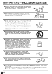
... relocating the product placed on the screen as a fixed point of the product. Be careful not to the product. Therefore, it must be injured by the manufacturer. I The LCD panel is dropped or applied with utmost care. do not place the product in installation; Use a damp cloth to follow the manufacturer's instructions. Sudden stops, excessive force and...
... relocating the product placed on the screen as a fixed point of the product. Be careful not to the product. Therefore, it must be injured by the manufacturer. I The LCD panel is dropped or applied with utmost care. do not place the product in installation; Use a damp cloth to follow the manufacturer's instructions. Sudden stops, excessive force and...
LC-20E1U Operation Manual
Page 6
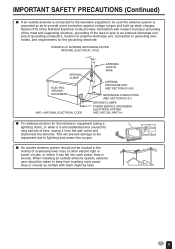
... of the mast and supporting structure, grounding of the lead-in the vicinity of antenna-discharge unit, connection to keep from the wall outlet and disconnect the antenna. When installing an outside antenna system should be located in wire to an antenna discharge unit, size of grounding conductors, Iocation of overhead power lines or other electric light or power circuits, or where it...
... of the mast and supporting structure, grounding of the lead-in the vicinity of antenna-discharge unit, connection to keep from the wall outlet and disconnect the antenna. When installing an outside antenna system should be located in wire to an antenna discharge unit, size of grounding conductors, Iocation of overhead power lines or other electric light or power circuits, or where it...
LC-20E1U Operation Manual
Page 7
... 3-5 SUPPLIED ACCESSORIES ...7 PREPARATION ...8-10 Using the Remote Control ...8 Batteries for the Remote Control 8 Power Connection ...9 Antenna Connection ...9, 10 FRONT AND REAR CONTROL OPTIONS 11-13 Removing the Back Cover ...13 Listening with Headphones ...13 EZ SETUP ...14 EZ SETUP during the First Power On 14 REMOTE CONTROL ...15 BASIC OPERATION ...15-18 Turning on POWER ...16 Switching TV/VIDEO [AV1/AV2/COMPONENT/TV] Modes 16 Sound Volume ...17 ON/OFF Standby ...17 Changing the Channels ...18 SELECTING MENU ITEMS ...19 Selecting Menu...
... 3-5 SUPPLIED ACCESSORIES ...7 PREPARATION ...8-10 Using the Remote Control ...8 Batteries for the Remote Control 8 Power Connection ...9 Antenna Connection ...9, 10 FRONT AND REAR CONTROL OPTIONS 11-13 Removing the Back Cover ...13 Listening with Headphones ...13 EZ SETUP ...14 EZ SETUP during the First Power On 14 REMOTE CONTROL ...15 BASIC OPERATION ...15-18 Turning on POWER ...16 Switching TV/VIDEO [AV1/AV2/COMPONENT/TV] Modes 16 Sound Volume ...17 ON/OFF Standby ...17 Changing the Channels ...18 SELECTING MENU ITEMS ...19 Selecting Menu...
LC-20E1U Operation Manual
Page 9
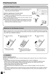
... remote sensor window of time, remove the batteries from batteries can shorten the life of remote control I The remote control may prevent proper operation. I Do not expose the remote control to leak chemicals. • Remove batteries when they become depleted and the remote control fails to liquid, and do not expose the remote control to operate, replace the batteries with high humidity. Cautions regarding use of the lighting or LCD TV set...
... remote sensor window of time, remove the batteries from batteries can shorten the life of remote control I The remote control may prevent proper operation. I Do not expose the remote control to leak chemicals. • Remove batteries when they become depleted and the remote control fails to liquid, and do not expose the remote control to operate, replace the batteries with high humidity. Cautions regarding use of the lighting or LCD TV set...
LC-20E1U Operation Manual
Page 10
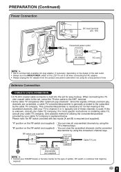
..., RF switch or combiner that might be required. 9 PDINOCPW1U2EVTR ANT. RF switch (not supplied) OUT IN Cable TV converter/ descrambler (not supplied) Two-set , screw the 75-ohm cable to the set signal splitter (not supplied) Cable TV Line A • Consult your SHARP Dealer or Service Center for the type of these channels is required (not supplied). PREPARATION (Continued) Power Connection VIDEO AV-IN 2/OUT L AUDIO R COMPONENT Y PB PR L AUDIO R VIDEO AV-IN 1 L AUDIO R S-VIDEO PHHEOANDE...
..., RF switch or combiner that might be required. 9 PDINOCPW1U2EVTR ANT. RF switch (not supplied) OUT IN Cable TV converter/ descrambler (not supplied) Two-set , screw the 75-ohm cable to the set signal splitter (not supplied) Cable TV Line A • Consult your SHARP Dealer or Service Center for the type of these channels is required (not supplied). PREPARATION (Continued) Power Connection VIDEO AV-IN 2/OUT L AUDIO R COMPONENT Y PB PR L AUDIO R VIDEO AV-IN 1 L AUDIO R S-VIDEO PHHEOANDE...

LC-20E1U Operation Manual
Page 11
... twin-lead cable (flat) OUTDOOR ANTENNA CONNECTION • Use one of the TV set. terminal on the rear of the following is generally a round cable with F-type connector that are more important than those for black & white television reception. Separate VHF and/or UHF Antennas UHF antenna 300-ohm twin-lead VHF antenna ANT. VHF/UHF antenna A. The following two diagrams if you connect an outdoor antenna. A 300-ohm...
... twin-lead cable (flat) OUTDOOR ANTENNA CONNECTION • Use one of the TV set. terminal on the rear of the following is generally a round cable with F-type connector that are more important than those for black & white television reception. Separate VHF and/or UHF Antennas UHF antenna 300-ohm twin-lead VHF antenna ANT. VHF/UHF antenna A. The following two diagrams if you connect an outdoor antenna. A 300-ohm...
LC-20E1U Operation Manual
Page 12
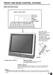
.... POWER indicator A green indicator lights when the power is off). FRONT AND REAR CONTROL OPTIONS Main unit (front view) Upper control panel VOL CH VOL (-)/(+) CH ( )/( ) MENU TV/VIDEO MAIN POWER MENU TV/VIDEO MAIN POWER The screen can be set up red when the SLEEP TIMER is set to on and a red indicator lights when in the standby mode (the indicator will not light when the main power is on . Adjustable range Speaker Remote sensor window SLEEP indicator The SLEEP indicator lights up...
.... POWER indicator A green indicator lights when the power is off). FRONT AND REAR CONTROL OPTIONS Main unit (front view) Upper control panel VOL CH VOL (-)/(+) CH ( )/( ) MENU TV/VIDEO MAIN POWER MENU TV/VIDEO MAIN POWER The screen can be set up red when the SLEEP TIMER is set to on and a red indicator lights when in the standby mode (the indicator will not light when the main power is on . Adjustable range Speaker Remote sensor window SLEEP indicator The SLEEP indicator lights up...
LC-20E1U Operation Manual
Page 14
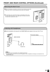
VIDEO AV-IN 2/OUT L AUDIO R COMPONENT Y PB PR L AUDIO R VIDEO AV-IN 1 L AUDIO R S-VIDEO PHHEOANDE ANT. PDINOCPW1U3EVTR c Rear terminal Headphones M On-screen display VOLUME 60 A • Headphones are not included in the supplied accessories. • No sound will be heard from the main unit speakers when a headphone mini-plug is connected into the rear terminal, remove the back cover. FRONT AND REAR CONTROL OPTIONS (Continued) Removing the Back Cover I Before connecting a connection cord into the...
VIDEO AV-IN 2/OUT L AUDIO R COMPONENT Y PB PR L AUDIO R VIDEO AV-IN 1 L AUDIO R S-VIDEO PHHEOANDE ANT. PDINOCPW1U3EVTR c Rear terminal Headphones M On-screen display VOLUME 60 A • Headphones are not included in the supplied accessories. • No sound will be heard from the main unit speakers when a headphone mini-plug is connected into the rear terminal, remove the back cover. FRONT AND REAR CONTROL OPTIONS (Continued) Removing the Back Cover I Before connecting a connection cord into the...
LC-20E1U Operation Manual
Page 15
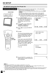
... MENU/ a/b/c/d The tuner will be displayed. START EZ SETUP? EZ SETUP EZ SETUP during the First Power On Control section of main unit MAIN POWER VOL CH MENU TV/VIDEO MAIN POWER I When you press MAIN POWER. (1) Insert the batteries into the remote control. (See page 8.) (2) Connect the antenna cable to the TV set. (See page 10.) (3) Connect the AC adapter to the DC input terminal of the main unit, to access EZ SETUP mode...
... MENU/ a/b/c/d The tuner will be displayed. START EZ SETUP? EZ SETUP EZ SETUP during the First Power On Control section of main unit MAIN POWER VOL CH MENU TV/VIDEO MAIN POWER I When you press MAIN POWER. (1) Insert the batteries into the remote control. (See page 8.) (2) Connect the antenna cable to the TV set. (See page 10.) (3) Connect the AC adapter to the DC input terminal of the main unit, to access EZ SETUP mode...
LC-20E1U Operation Manual
Page 16
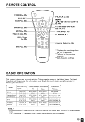
.... REMOTE CONTROL POWER (p. 17) DISPLAY*1 SLEEP (p. 20) BRIGHT (p. 21) MUTE (p. 17) VOL(+)/(-) (p. 17) CH ( )/( ) (p. 18) MTS*3 (p. 17) POWER SLEEP DISPLAY MENU PIC. FLIP (p. 22) MENU/ a/b/c/d (Cursor control) (p. 19) CC (CLOSED CAPTION) (pp. 30, 31) TV/VIDEO (p. 16) FLASHBACK*2 Channel Select (p. 18) *1 Displays the receiving channel for 10 seconds. *2 Returns to comply with the TV broadcasting system in TV mode and Video mode. *The 3 Dimensional Y/C separation circuit is factory set to the previous channel. *3 Selects audio settings.
.... REMOTE CONTROL POWER (p. 17) DISPLAY*1 SLEEP (p. 20) BRIGHT (p. 21) MUTE (p. 17) VOL(+)/(-) (p. 17) CH ( )/( ) (p. 18) MTS*3 (p. 17) POWER SLEEP DISPLAY MENU PIC. FLIP (p. 22) MENU/ a/b/c/d (Cursor control) (p. 19) CC (CLOSED CAPTION) (pp. 30, 31) TV/VIDEO (p. 16) FLASHBACK*2 Channel Select (p. 18) *1 Displays the receiving channel for 10 seconds. *2 Returns to comply with the TV broadcasting system in TV mode and Video mode. *The 3 Dimensional Y/C separation circuit is factory set to the previous channel. *3 Selects audio settings.
LC-20E1U Operation Manual
Page 17
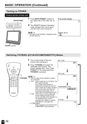
BASIC OPERATION (Continued) Turning on POWER Control section of main unit 1 Press MAIN POWER, located on M On-screen display MAIN POWER the upper side of the main unit, to green and the main unit is turned on . 2 VOL CH MENU TV/VIDEO MAIN POWER 2 The POWER indicator instantane- ously changes from red to on . STEREO A • The input mode indication disappears after several seconds.
BASIC OPERATION (Continued) Turning on POWER Control section of main unit 1 Press MAIN POWER, located on M On-screen display MAIN POWER the upper side of the main unit, to green and the main unit is turned on . 2 VOL CH MENU TV/VIDEO MAIN POWER 2 The POWER indicator instantane- ously changes from red to on . STEREO A • The input mode indication disappears after several seconds.

LC-20E1U Operation Manual
Page 20
...-N), set the color system before using the menu screen. REMA I N ] SELECT : ADJUST : (Pages 24, 25) V I DEO ADJUST ( TV ) RE TURN P I CTURE [ 30] T I NT [ 0] COLOR [ 0] BLACK LEVEL [ 0 ] SHARPNESS [ 0 ] COLOR SYSTEM [ N358 ] RESET EX I T : MENU SELECT : ENTER : EX I T : MENU (Pages 21, 22 and 26) PRESET RE TURN BR I GHTNESS [ BR I GHT ] AUTO POWER OFF [ OFF ] P I CTURE F L I P [ NORMAL ] AV2 I N / OUT [ I N ] SELECT : ADJUST : (Page 31) CLOSED CAPT I ON RE TURN CC/ TEXT [OFF ] EX I T : MENU SELECT : ADJUST...
...-N), set the color system before using the menu screen. REMA I N ] SELECT : ADJUST : (Pages 24, 25) V I DEO ADJUST ( TV ) RE TURN P I CTURE [ 30] T I NT [ 0] COLOR [ 0] BLACK LEVEL [ 0 ] SHARPNESS [ 0 ] COLOR SYSTEM [ N358 ] RESET EX I T : MENU SELECT : ENTER : EX I T : MENU (Pages 21, 22 and 26) PRESET RE TURN BR I GHTNESS [ BR I GHT ] AUTO POWER OFF [ OFF ] P I CTURE F L I P [ NORMAL ] AV2 I N / OUT [ I N ] SELECT : ADJUST : (Page 31) CLOSED CAPT I ON RE TURN CC/ TEXT [OFF ] EX I T : MENU SELECT : ADJUST...
LC-20E1U Operation Manual
Page 21
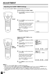
... SLEEP TIMER is displayed. REMA I N 60 REMA I N POWER SLEEP DISPLAY MENU PIC. ADJUSTMENT Adjusting the SLEEP TIMER Settings You can set the SLEEP TIMER to automatically turn off the MAIN POWER on the TV set or press the POWER button on the remote control, the SLEEP TIMER setting is cancelled and the SLEEP indicator goes out. • 5 minutes before the SLEEP TIMER turns off the TV, 5 REMAIN is displayed on the MENU screen 1 Press MENU to display the MENU screen. 2 Press a/b to move the cursor to SLEEP TIMER...
... SLEEP TIMER is displayed. REMA I N 60 REMA I N POWER SLEEP DISPLAY MENU PIC. ADJUSTMENT Adjusting the SLEEP TIMER Settings You can set the SLEEP TIMER to automatically turn off the MAIN POWER on the TV set or press the POWER button on the remote control, the SLEEP TIMER setting is cancelled and the SLEEP indicator goes out. • 5 minutes before the SLEEP TIMER turns off the TV, 5 REMAIN is displayed on the MENU screen 1 Press MENU to display the MENU screen. 2 Press a/b to move the cursor to SLEEP TIMER...

LC-20E1U Operation Manual
Page 25
A • See page 25 for the settings. 7 Press MENU to return to change the setting. SELECT : ENTER : RE TURN P I T : MENU 24 SELECT : ADJUST : EX I T : MENU + EX I CTURE 30 - ADJUSTMENT (Continued) Adjusting the VIDEO ADJUST Settings POWER SLEEP DISPLAY PIC. SELECT : ENTER : V I DEO ADJUST ( TV) RE TURN P I CTURE [ 30] T I NT [ 0] COLOR [ 0] BLACK LEVEL [ 0 ] SHARPNESS [ 0 ] COLOR SYSTEM [ N358 ] RESET EX I T : MENU 6 Press c/d to the main screen. MENU SLEEP T IMER V I DEO ADJUST PRESET CLOSED CAPT I ON V-CH I T : MENU 4 Press a/b to move the cursor to...
A • See page 25 for the settings. 7 Press MENU to return to change the setting. SELECT : ENTER : RE TURN P I T : MENU 24 SELECT : ADJUST : EX I T : MENU + EX I CTURE 30 - ADJUSTMENT (Continued) Adjusting the VIDEO ADJUST Settings POWER SLEEP DISPLAY PIC. SELECT : ENTER : V I DEO ADJUST ( TV) RE TURN P I CTURE [ 30] T I NT [ 0] COLOR [ 0] BLACK LEVEL [ 0 ] SHARPNESS [ 0 ] COLOR SYSTEM [ N358 ] RESET EX I T : MENU 6 Press c/d to the main screen. MENU SLEEP T IMER V I DEO ADJUST PRESET CLOSED CAPT I ON V-CH I T : MENU 4 Press a/b to move the cursor to...

LC-20E1U Operation Manual
Page 31
... set enters CAPTION mode automatically. FLIP MUTE BRIGHT CC TV/VIDEO VOL CH FLASHBACK CC MUTE Directly setting the CLOSED CAPTION 1 Press CC to display the CC/TEXT screen. 2 Press CC to call up the On-Screen Display while viewing a Closed Caption broadcast, the closed captions will offer closed captioning. The CAPTION mode shows subscripts of dialogs and commentaries of TV dramas and news programs while allowing a clear view of the TV programs. POWER SLEEP DISPLAY MENU...
... set enters CAPTION mode automatically. FLIP MUTE BRIGHT CC TV/VIDEO VOL CH FLASHBACK CC MUTE Directly setting the CLOSED CAPTION 1 Press CC to display the CC/TEXT screen. 2 Press CC to call up the On-Screen Display while viewing a Closed Caption broadcast, the closed captions will offer closed captioning. The CAPTION mode shows subscripts of dialogs and commentaries of TV dramas and news programs while allowing a clear view of the TV programs. POWER SLEEP DISPLAY MENU...
LC-20E1U Operation Manual
Page 41
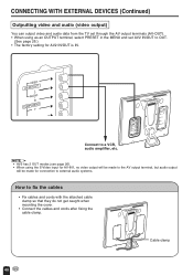
... factory setting for connection to external audio systems. How to a VCR, audio amplifier, etc. PDINOCPW1U2EVTR Cable clamp 40 VIDEO AV-IN 2/OUT L AUDIO R COMPONENT Y PB PR L AUDIO R VIDEO AV-IN 1 L AUDIO R S-VIDEO PHHEOANDE ANT. VIDEO AV-IN2/OUT L AUDIO R COMPONENT Y VIDEO AV-IN 2/OUT L AUDIO R COMPONENT Y PB PR L AUDIO R VIDEO AV-IN 1 L AUDIO R S-VIDEO PHHEOANDE ANT. A • AV2 has 2 OUT modes (see page 26). • When using as an OUTPUT terminal, select PRESET in the MENU and set through...
... factory setting for connection to external audio systems. How to a VCR, audio amplifier, etc. PDINOCPW1U2EVTR Cable clamp 40 VIDEO AV-IN 2/OUT L AUDIO R COMPONENT Y PB PR L AUDIO R VIDEO AV-IN 1 L AUDIO R S-VIDEO PHHEOANDE ANT. VIDEO AV-IN2/OUT L AUDIO R COMPONENT Y VIDEO AV-IN 2/OUT L AUDIO R COMPONENT Y PB PR L AUDIO R VIDEO AV-IN 1 L AUDIO R S-VIDEO PHHEOANDE ANT. A • AV2 has 2 OUT modes (see page 26). • When using as an OUTPUT terminal, select PRESET in the MENU and set through...
LC-20E1U Operation Manual
Page 42
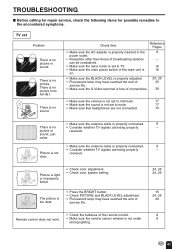
... no sound. Picture is not received. Check item Reference Pages • Make sure the AC adapter is properly inserted in the 9 power outlet. • Reception other than those of the remote control. 8 Remote control does not work. • Make sure the remote sensor window is not under 8 strong lighting. 41 picture or received. Picture is light or improperly tinted. • Check color adjustment. • Check color system setting. TROUBLESHOOTING I Before calling for repair service...
... no sound. Picture is not received. Check item Reference Pages • Make sure the AC adapter is properly inserted in the 9 power outlet. • Reception other than those of the remote control. 8 Remote control does not work. • Make sure the remote sensor window is not under 8 strong lighting. 41 picture or received. Picture is light or improperly tinted. • Check color adjustment. • Check color system setting. TROUBLESHOOTING I Before calling for repair service...

LC-20E1U Operation Manual
Page 46
... state law, the warranties set forth below . ALL EXPRESS AND IMPLIED WARRANTIES INCLUDING THE WARRANTIES OF MERCHANTABILITY, FITNESS FOR USE, AND FITNESS FOR A PARTICULAR PURPOSE ARE SPECIFICALLY EXCLUDED. Nor shall Sharp be liable or in any way responsible for the period(s) set forth below . Some states do to Obtain Service: LC-20E1U LCD Color Television (Be sure to the purchaser for parts or labor for...
... state law, the warranties set forth below . ALL EXPRESS AND IMPLIED WARRANTIES INCLUDING THE WARRANTIES OF MERCHANTABILITY, FITNESS FOR USE, AND FITNESS FOR A PARTICULAR PURPOSE ARE SPECIFICALLY EXCLUDED. Nor shall Sharp be liable or in any way responsible for the period(s) set forth below . Some states do to Obtain Service: LC-20E1U LCD Color Television (Be sure to the purchaser for parts or labor for...

LC-20E1U Operation Manual
Page 47
... the owner's manual. (b) Any Sharp product tampered with proof of purchase and a copy of information. This warranty shall not apply to: (a) Any defects caused or repairs required as a result of abusive operation, negligence, accident, improper installation or inappropriate use of 27" or larger and on any Sharp television with the screen size of the product including but not limited to earphones, remote controls, AC adapters...
... the owner's manual. (b) Any Sharp product tampered with proof of purchase and a copy of information. This warranty shall not apply to: (a) Any defects caused or repairs required as a result of abusive operation, negligence, accident, improper installation or inappropriate use of 27" or larger and on any Sharp television with the screen size of the product including but not limited to earphones, remote controls, AC adapters...


