HT-SL70 Operation Manual
Page 8
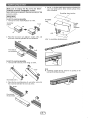
... unplug the AC power lead before installing the unit or changing the position. Sound bar joint A 2. Place the two sound bars near to each other and slot in the sound bar joint and its cover as below . Front side of the sound bar SOUND BAR HOME THEATER SYSTEM HT-SL70 Left For 52" TV sound bar assembly 1. Cover Note: ● Sound bar stand can be removed by...
... unplug the AC power lead before installing the unit or changing the position. Sound bar joint A 2. Place the two sound bars near to each other and slot in the sound bar joint and its cover as below . Front side of the sound bar SOUND BAR HOME THEATER SYSTEM HT-SL70 Left For 52" TV sound bar assembly 1. Cover Note: ● Sound bar stand can be removed by...
HT-SL70 Operation Manual
Page 10
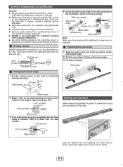
... 3 Fix a wall mount plug (not supplied) into the hole using a hammer, until it can cause damage and injury. The sound bar may get damaged. ● SHARP is not responsible for accidents resulting from falling when mounting on the wall. ● Before mounting, check the wall strength. (Do ...Use appropriate ones. ● Check all screws are fully tightened. (screws are not supplied) Installing the sound bar 1 Align the wall mount slot at the sound bar to the wall mount angle. 2 Slot the sound bar into each hole as below for looseness. ● Select a good location. If not, accidents...
... 3 Fix a wall mount plug (not supplied) into the hole using a hammer, until it can cause damage and injury. The sound bar may get damaged. ● SHARP is not responsible for accidents resulting from falling when mounting on the wall. ● Before mounting, check the wall strength. (Do ...Use appropriate ones. ● Check all screws are fully tightened. (screws are not supplied) Installing the sound bar 1 Align the wall mount slot at the sound bar to the wall mount angle. 2 Slot the sound bar into each hole as below for looseness. ● Select a good location. If not, accidents...
HT-SL70 Operation Manual
Page 11
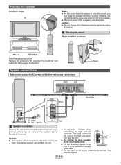
...lower impedance speaker can place the speaker anywhere you like. Placing the system Installation image: TV Notes: ● As the sound from the system is not removable. SUBWOOFER SYSTEM ACTIVE SUBWOOFER SYSTEM HT-SL70 ACTIVE SUBHWT-OSLO7F0ER SYSTEM System connections Make sure to unplug the AC power cord...the TV as shown. Subwoofer Right Left Stand White Sound Bar AC outlet Red AC 120 V ~ 60 Hz Speaker connection Connect the wire without insulation tube to the plus (+) terminal. Caution: ● Do not change the installation direction when the unit is the one on the ...
...lower impedance speaker can place the speaker anywhere you like. Placing the system Installation image: TV Notes: ● As the sound from the system is not removable. SUBWOOFER SYSTEM ACTIVE SUBWOOFER SYSTEM HT-SL70 ACTIVE SUBHWT-OSLO7F0ER SYSTEM System connections Make sure to unplug the AC power cord...the TV as shown. Subwoofer Right Left Stand White Sound Bar AC outlet Red AC 120 V ~ 60 Hz Speaker connection Connect the wire without insulation tube to the plus (+) terminal. Caution: ● Do not change the installation direction when the unit is the one on the ...


