
Service Manual
Page 1
... speaker) and CP-CN300R (surround speakers). • In the interests of HT-CN300 (main unit), CP-CN300F (front speakers), CP-CN300C (center speaker) and CP-CN300R (surround speakers). ONLY) SHARP CORPORATION This document has been published to change without notice. The contents are ...subject to be used for after sales service only. S7250HTCN300/ HOME CINEMA COMMAND MODEL HT-CN300(S) HT-CN300 Home Cinema Command consisting of user-safety the...
... speaker) and CP-CN300R (surround speakers). • In the interests of HT-CN300 (main unit), CP-CN300F (front speakers), CP-CN300C (center speaker) and CP-CN300R (surround speakers). ONLY) SHARP CORPORATION This document has been published to change without notice. The contents are ...subject to be used for after sales service only. S7250HTCN300/ HOME CINEMA COMMAND MODEL HT-CN300(S) HT-CN300 Home Cinema Command consisting of user-safety the...
Service Manual
Page 2
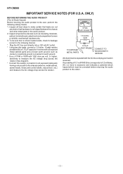
... 1000 ohm per volt, or higher, sensitivity to measure the AC voltage drop across the resistor (See diagram). * Connect the resistor connection to the owner. - 2 - HT-CN300 IMPORTANT SERVICE NOTES (FOR U.S.A. ONLY) BEFORE RETURNING THE AUDIO PRODUCT (Fire & Shock Hazard) Before returning the audio product to earth ground. * Use a VTVM or VOM...
... 1000 ohm per volt, or higher, sensitivity to measure the AC voltage drop across the resistor (See diagram). * Connect the resistor connection to the owner. - 2 - HT-CN300 IMPORTANT SERVICE NOTES (FOR U.S.A. ONLY) BEFORE RETURNING THE AUDIO PRODUCT (Fire & Shock Hazard) Before returning the audio product to earth ground. * Use a VTVM or VOM...
Service Manual
Page 3
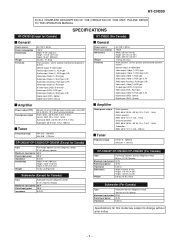
... DESCRIPTION OF THE OPERATION OF THIS UNIT, PLEASE REFER TO THE OPERATION MANUAL. SPECIFICATIONS HT-CN300 (Except for Canada) General Power source Power consumption Dimensions Weight Terminals AC 120 V, 60 Hz 195 W Width: 9-1/8" (230 mm) Height: 14-7/8" ...each Subwoofer (Except for Canada) Type Subwoofer System (Magnetic shield) 6-1/4" (160 mm) Woofer Maximum input power 60 W Rated input power 30 W Impedance 6 ohms HT-CN300 (For Canada) General Power source Power consumption Dimensions Weight Terminals AC 120 V, 60 Hz 195 W Width: 230 mm (9-1/8") Height: 377 mm (14-7/8") Depth: ...
... DESCRIPTION OF THE OPERATION OF THIS UNIT, PLEASE REFER TO THE OPERATION MANUAL. SPECIFICATIONS HT-CN300 (Except for Canada) General Power source Power consumption Dimensions Weight Terminals AC 120 V, 60 Hz 195 W Width: 9-1/8" (230 mm) Height: 14-7/8" ...each Subwoofer (Except for Canada) Type Subwoofer System (Magnetic shield) 6-1/4" (160 mm) Woofer Maximum input power 60 W Rated input power 30 W Impedance 6 ohms HT-CN300 (For Canada) General Power source Power consumption Dimensions Weight Terminals AC 120 V, 60 Hz 195 W Width: 230 mm (9-1/8") Height: 377 mm (14-7/8") Depth: ...
Service Manual
Page 4
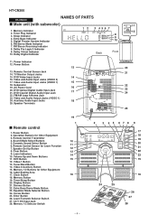
... II Indicator 9. Volume Up and Down Buttons 11. Power Indicator 12. Video and Audio Input Jacks (VIDEO 1) 15 18. Auxiliary Audio Input Jacks 18 25. HT-CN300 HT-CN300 NAMES OF PARTS Main unit (with subwoofer) 1.
... II Indicator 9. Volume Up and Down Buttons 11. Power Indicator 12. Video and Audio Input Jacks (VIDEO 1) 15 18. Auxiliary Audio Input Jacks 18 25. HT-CN300 HT-CN300 NAMES OF PARTS Main unit (with subwoofer) 1.

Service Manual
Page 5
... (left): White Center Speaker: Green Surround Speaker (right): Gray Surround Speaker (left): Blue 4. Note: Fix the remote control sensor on a flat surface. Mounting Slot 5. Front 1 HT-CN300 3 Side 2 3 Bottom 5 4 6 - 5 - Remote Sensor 2. CP-CN300F/CP-CN300C/CP-CN300R 1. Mounting Screw Holes Speaker cushion: Attach the cushions to the bottom of the speakers to...
... (left): White Center Speaker: Green Surround Speaker (right): Gray Surround Speaker (left): Blue 4. Note: Fix the remote control sensor on a flat surface. Mounting Slot 5. Front 1 HT-CN300 3 Side 2 3 Bottom 5 4 6 - 5 - Remote Sensor 2. CP-CN300F/CP-CN300C/CP-CN300R 1. Mounting Screw Holes Speaker cushion: Attach the cushions to the bottom of the speakers to...
Service Manual
Page 6
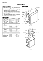
HT-CN300 DISASSEMBLY Caution on static electricity of integrated circuits and other circuits when servicing. Screw C1) x4 6-2 2. Socket E2) x1 3. Socket F3) x1 7 Video PWB 1. PWB 1. ... Follow the below-mentioned notes when disassembling the unit and reassembling it, to disassemble the unit. 2. HT-CN300 Top Cover A Top Cover B (A1)x2 ø3x8mm (D1)x6 ø3x8mm (B1)x2 ø2.5x12mm LCD Cover HT-CN300 STEP REMOVAL PROCEDURE FIGURE 1 Top Cover B 1. Flat Cable C2) x3 3. Socket J2) x4 10 Speaker PWB...
HT-CN300 DISASSEMBLY Caution on static electricity of integrated circuits and other circuits when servicing. Screw C1) x4 6-2 2. Socket E2) x1 3. Socket F3) x1 7 Video PWB 1. PWB 1. ... Follow the below-mentioned notes when disassembling the unit and reassembling it, to disassemble the unit. 2. HT-CN300 Top Cover A Top Cover B (A1)x2 ø3x8mm (D1)x6 ø3x8mm (B1)x2 ø2.5x12mm LCD Cover HT-CN300 STEP REMOVAL PROCEDURE FIGURE 1 Top Cover B 1. Flat Cable C2) x3 3. Socket J2) x4 10 Speaker PWB...

Service Manual
Page 7
... not be disassembled. PWB (J2)x1 (K1)x1 ø3x8mm (J1)x6 ø3x8mm AMP. Subwoofer Box DSP PWB Rear Panel (G1)x3 ø3x8mm HT-CN300 (G2)x1 Tuner PWB Video PWB (J2)x1 Tuner PWB (D1)x19 ø3x8mm Figure 7-1 (H1)x2 ø3x8mm (G2)x1 Audio PWB (J2)x2...
... not be disassembled. PWB (J2)x1 (K1)x1 ø3x8mm (J1)x6 ø3x8mm AMP. Subwoofer Box DSP PWB Rear Panel (G1)x3 ø3x8mm HT-CN300 (G2)x1 Tuner PWB Video PWB (J2)x1 Tuner PWB (D1)x19 ø3x8mm Figure 7-1 (H1)x2 ø3x8mm (G2)x1 Audio PWB (J2)x2...
Service Manual
Page 8
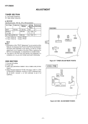
... parts in the FM front end section are prepared in the factory so that its further adjustment is not needed at the field. ADJUSTMENT POINTS - 8 - HT-CN300 ADJUSTMENT TUNER SECTION fL: Low-range frequency fH: High-range frequency • AM IF/RF Signal generator: 400 Hz, 30%, AM modulated Test Stage AM...
... parts in the FM front end section are prepared in the factory so that its further adjustment is not needed at the field. ADJUSTMENT POINTS - 8 - HT-CN300 ADJUSTMENT TUNER SECTION fL: Low-range frequency fH: High-range frequency • AM IF/RF Signal generator: 400 Hz, 30%, AM modulated Test Stage AM...
Service Manual
Page 9
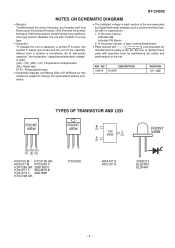
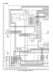
HT-CN300 NOTES ON SCHEMATIC DIAGRAM • Resistor: To differentiate the units of resistors, such symbol as K and M are used: the symbol K means 1000 ohm and the ...
HT-CN300 NOTES ON SCHEMATIC DIAGRAM • Resistor: To differentiate the units of resistors, such symbol as K and M are used: the symbol K means 1000 ohm and the ...

Service Manual
Page 11
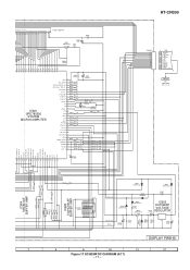
HT-CN300 +B2 M_12V +B3 +9V -B2 -5V -B3 -9V +B4 +5V +B5 +3V3 +B6 FANB -VP VF1 VF2 +B7 +5V 12 VF1 FL690 FL DISPLAY 4 11 ...
HT-CN300 +B2 M_12V +B3 +9V -B2 -5V -B3 -9V +B4 +5V +B5 +3V3 +B6 FANB -VP VF1 VF2 +B7 +5V 12 VF1 FL690 FL DISPLAY 4 11 ...

Service Manual
Page 12
HT-CN300 IC701 TVHC574T LATCH 1 OE VCC 20 2 D0 O0 19 3 D1 O1 18 4 D2 O2 17 5 D3 O3 16 6 D4 O4 15 7 D5 O5 14 8 D6 ...
HT-CN300 IC701 TVHC574T LATCH 1 OE VCC 20 2 D0 O0 19 3 D1 O1 18 4 D2 O2 17 5 D3 O3 16 6 D4 O4 15 7 D5 O5 14 8 D6 ...

Service Manual
Page 13
HT-CN300 R FROM AUDIO SECTION +B4 +5V 37 41 RX2 RX4 CKO RCK CK TDO IC708 DTI1 AK4586VQ DTI2 ADC/DAC/DIR DTI3 CONVERTER TI/EXTCLK RIN ...
HT-CN300 R FROM AUDIO SECTION +B4 +5V 37 41 RX2 RX4 CKO RCK CK TDO IC708 DTI1 AK4586VQ DTI2 ADC/DAC/DIR DTI3 CONVERTER TI/EXTCLK RIN ...
Service Manual
Page 14
... 0.001 C242 1/50 (N.P.) R235 2.2K C Q230 B 2SC2878 B R143 100K R234 820 E R236 100 C233 1/50 (N.P.) CNP203 1 2 3 4 5 6 7 8 CNS204 BI204 TERMINAL PWB-B5 IC202 LM4766T POWER AMP. HT-CN300 A B C AMP. GNDA 5 GNDB 10 VCCB 15 VEE 4 VCCA 2 C221 22/35 (N.P.) C212 22/35 (N.P.) R226 R227 R228 R214 R215 R216 1K 8 +INA 220 7 -INA 22K...
... 0.001 C242 1/50 (N.P.) R235 2.2K C Q230 B 2SC2878 B R143 100K R234 820 E R236 100 C233 1/50 (N.P.) CNP203 1 2 3 4 5 6 7 8 CNS204 BI204 TERMINAL PWB-B5 IC202 LM4766T POWER AMP. HT-CN300 A B C AMP. GNDA 5 GNDB 10 VCCB 15 VEE 4 VCCA 2 C221 22/35 (N.P.) C212 22/35 (N.P.) R226 R227 R228 R214 R215 R216 1K 8 +INA 220 7 -INA 22K...
Service Manual
Page 15
HT-CN300 D201 DS1SS133 Q200 KRC107 M 23 1 C204 100/10 Z201 DZ3.9BSB E R208 R207 Q204 B KTA1271 Y R209 22K C R201 R299 1K R200 820K D200 DS1SS133 Z200 ...
HT-CN300 D201 DS1SS133 Q200 KRC107 M 23 1 C204 100/10 Z201 DZ3.9BSB E R208 R207 Q204 B KTA1271 Y R209 22K C R201 R299 1K R200 820K D200 DS1SS133 Z200 ...
Service Manual
Page 16
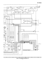
... GREEN IC604 VHC541AF BUFFER AMP. LED699 LE204HT RED F R699 1.5K R698 300 CNP701 TO DSP PWB P20 1 - C660 0.022 1 2 3 4 5 6 Figure 16 SCHEMATIC DIAGRAM (3/17) - 16 - HT-CN300 A B C FW7 1 CNP670 AC_RLY 1 D_GND 2 FUNC_DVD 3 VREC_MUTE 4 CLK 5 V_SW1 6 DATA 7 V_SW2 8 V_MUTE 9 D OSD_CS1 10 10 CON703 TO DSP PWB P20 1 -
... GREEN IC604 VHC541AF BUFFER AMP. LED699 LE204HT RED F R699 1.5K R698 300 CNP701 TO DSP PWB P20 1 - C660 0.022 1 2 3 4 5 6 Figure 16 SCHEMATIC DIAGRAM (3/17) - 16 - HT-CN300 A B C FW7 1 CNP670 AC_RLY 1 D_GND 2 FUNC_DVD 3 VREC_MUTE 4 CLK 5 V_SW1 6 DATA 7 V_SW2 8 V_MUTE 9 D OSD_CS1 10 10 CON703 TO DSP PWB P20 1 -
Service Manual
Page 17
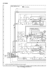
.../6.3 R610 1K C611 12P(CH) X611 C612 18P(CH) R614 10K 1K R672 10K 1K R673 10K 1K R674 10K 1K R675 10K C622 4.7/50 HT-CN300 CNP601 14 13 12 11 10 9 8 7 6 5 4 3 2 1 14 FW8 -20DBATT F_RLY FAN_CONT C_RLY CCB_CE0 S_RLY CLK W_RLY DATA THERMO CCB_DO PROTECT D_GND POWER_LEVEL 1 CNP708 TO DSP...
.../6.3 R610 1K C611 12P(CH) X611 C612 18P(CH) R614 10K 1K R672 10K 1K R673 10K 1K R674 10K 1K R675 10K C622 4.7/50 HT-CN300 CNP601 14 13 12 11 10 9 8 7 6 5 4 3 2 1 14 FW8 -20DBATT F_RLY FAN_CONT C_RLY CCB_CE0 S_RLY CLK W_RLY DATA THERMO CCB_DO PROTECT D_GND POWER_LEVEL 1 CNP708 TO DSP...

Service Manual
Page 18
HT-CN300 A DSP PWB-A1 (1/3) [1,2,3] SW5V 1 +B +B [2,3] UNSW5V 2 [2] DG_CNG 3 [2] FUNCDVD 4 B [2,3] 3.3V 5 +3.3V +B [1,2,3] DGND 6 +B IC702 +B TVHC574T C738 0.022 +B C736 LATCH 0.022 C735 10/16 +B C781 47/16 +B C782 0.1 1 2 3 4 5 VIN ...
HT-CN300 A DSP PWB-A1 (1/3) [1,2,3] SW5V 1 +B +B [2,3] UNSW5V 2 [2] DG_CNG 3 [2] FUNCDVD 4 B [2,3] 3.3V 5 +3.3V +B [1,2,3] DGND 6 +B IC702 +B TVHC574T C738 0.022 +B C736 LATCH 0.022 C735 10/16 +B C781 47/16 +B C782 0.1 1 2 3 4 5 VIN ...

Service Manual
Page 20
HT-CN300 DSP PWB-A1 (2/3) A [1,2,3] UNSW5V 2 +B [1,2,3] DGND 6 [1,3] 3.3V 5 +B L702 2.2µH C744 0.022 +B R926 220 Q703 2SD1898 2 1 3 Z704 3 02CZ3.9X 1 2 C907 47/10 C909 1000/6.3 +B D_GND +3.3V_SWD +3.3V_BACKUP +B +B B ...
HT-CN300 DSP PWB-A1 (2/3) A [1,2,3] UNSW5V 2 +B [1,2,3] DGND 6 [1,3] 3.3V 5 +B L702 2.2µH C744 0.022 +B R926 220 Q703 2SD1898 2 1 3 Z704 3 02CZ3.9X 1 2 C907 47/10 C909 1000/6.3 +B D_GND +3.3V_SWD +3.3V_BACKUP +B +B B ...

Service Manual
Page 21
... 8.38 MHz C902 15P (CH) C903 15P (CH) C905 18P (CH) ATT20DB [3] 44 FANCNT [3] 45 FM SIGNAL R956 47K R957 47K R958 47K R959 47K HT-CN300 39 F_RLY [3] 40 C_RLY [3] 41 S_RLY [3] 42 W_RLY [3] 42 W_SP_RLY [3] 7 DSP_INTREQ [1] 8 DSP_ABOUT [1] 9 ROM [1] 10 DSP_UC17 [1] 11 DSP_UC16 [1] 12 DSP_UC15 [1] 13 DSP_RESET [1] 14 DSP_CS [1] 15 DSP_SCCLK...
... 8.38 MHz C902 15P (CH) C903 15P (CH) C905 18P (CH) ATT20DB [3] 44 FANCNT [3] 45 FM SIGNAL R956 47K R957 47K R958 47K R959 47K HT-CN300 39 F_RLY [3] 40 C_RLY [3] 41 S_RLY [3] 42 W_RLY [3] 42 W_SP_RLY [3] 7 DSP_INTREQ [1] 8 DSP_ABOUT [1] 9 ROM [1] 10 DSP_UC17 [1] 11 DSP_UC16 [1] 12 DSP_UC15 [1] 13 DSP_RESET [1] 14 DSP_CS [1] 15 DSP_SCCLK...

Service Manual
Page 22
HT-CN300 DSP_FROUT[1] DSP_SROUT[1] DSP_FLOUT [1] DSP_COUT [1] DSP_SLOUT[1] DSP_SWOU [T1] C810 10/16 A DSP PWB-A1 (3/3) 27 28 26 25 24 23 C806 10/16 C809 10/16 ...
HT-CN300 DSP_FROUT[1] DSP_SROUT[1] DSP_FLOUT [1] DSP_COUT [1] DSP_SLOUT[1] DSP_SWOU [T1] C810 10/16 A DSP PWB-A1 (3/3) 27 28 26 25 24 23 C806 10/16 C809 10/16 ...


