
Service Manual
Page 1
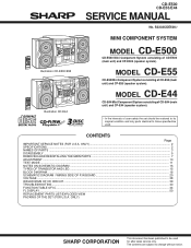
... WAVEFORMS OF CD CIRCUIT ...39 TROUBLESHOOTING ...40 FUNCTION TABLE OF IC ...44 FL DISPLAY ...50 REPLACEMENT PARTS LIST/EXPLODED VIEW PACKING OF THE SET (FOR U.S.A. ONLY) SHARP CORPORATION This document has been published to be used . S3333CDE500// Illustration CD-E500/E55 Illustration CD-E44 MINI COMPONENT SYSTEM MODEL CD-E500 CD-E500 Mini Component System consisting of CD-E55 (main unit) and CP-E55 (speaker system). CD-E500 CD-E55/E44 SERVICE MANUAL No. MODEL CD-E44 CD-E44 Mini Component System consisting...
... WAVEFORMS OF CD CIRCUIT ...39 TROUBLESHOOTING ...40 FUNCTION TABLE OF IC ...44 FL DISPLAY ...50 REPLACEMENT PARTS LIST/EXPLODED VIEW PACKING OF THE SET (FOR U.S.A. ONLY) SHARP CORPORATION This document has been published to be used . S3333CDE500// Illustration CD-E500/E55 Illustration CD-E44 MINI COMPONENT SYSTEM MODEL CD-E500 CD-E500 Mini Component System consisting of CD-E55 (main unit) and CP-E55 (speaker system). CD-E500 CD-E55/E44 SERVICE MANUAL No. MODEL CD-E44 CD-E44 Mini Component System consisting...
Service Manual
Page 2
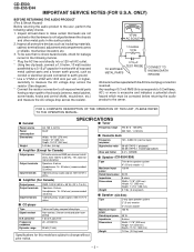
... with all protective devices such as conduit or electrical ground connected to 20 kHz, 10% total harmonic distortion Speakers: 8 ohms Headphones: 16 - 50 ohms (recommended: 32 ohms) Video/Auxiliary (audio signal): 500 mV/47 k ohms s Amplifier (For Canada) Output power Output terminals Input terminals RMS: 100 W (50 W + 50 W) (10 % T.H.D.) Speakers: 8 ohms Headphones: 16 - 50 ohms (recommended: 32 ohms) Video/Auxiliary (audio signal): 500 mV/47 k ohms s CD player Type Signal readout D/A converter Frequency response Dynamic range 3-disc multi-play compact disc player Non-contact...
... with all protective devices such as conduit or electrical ground connected to 20 kHz, 10% total harmonic distortion Speakers: 8 ohms Headphones: 16 - 50 ohms (recommended: 32 ohms) Video/Auxiliary (audio signal): 500 mV/47 k ohms s Amplifier (For Canada) Output power Output terminals Input terminals RMS: 100 W (50 W + 50 W) (10 % T.H.D.) Speakers: 8 ohms Headphones: 16 - 50 ohms (recommended: 32 ohms) Video/Auxiliary (audio signal): 500 mV/47 k ohms s CD player Type Signal readout D/A converter Frequency response Dynamic range 3-disc multi-play compact disc player Non-contact...
Service Manual
Page 3
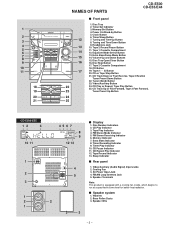
... FM Stereo Mode Indicator 5. CD Repeat Play Indicator 12. Sleep Indicator s Rear panel 1. FM/AM Loop Antenna Jack 5. Tuning and Time Up Button 8. Tape 2 Record Pause Button 14 11. Volume Up and Down Buttons 15. CD Track Down or Fast Reverse, Tape 2 Rewind, Tuner Preset Down Button 22. Tape Play Indicator 4. Cooling Fan 3. s Speaker system 1. Speaker Wire 3 - 3 - Memory/Set Button 4. Headphone Jack 13 10. Tuner (Band) Button 23. Woofers 2. Power On/Stand-by Button 5. CD Play or Repeat, Tape Play Button 25. AC Power Input Jack 4. Equalizer...
... FM Stereo Mode Indicator 5. CD Repeat Play Indicator 12. Sleep Indicator s Rear panel 1. FM/AM Loop Antenna Jack 5. Tuning and Time Up Button 8. Tape 2 Record Pause Button 14 11. Volume Up and Down Buttons 15. CD Track Down or Fast Reverse, Tape 2 Rewind, Tuner Preset Down Button 22. Tape Play Indicator 4. Cooling Fan 3. s Speaker system 1. Speaker Wire 3 - 3 - Memory/Set Button 4. Headphone Jack 13 10. Tuner (Band) Button 23. Woofers 2. Power On/Stand-by Button 5. CD Play or Repeat, Tape Play Button 25. AC Power Input Jack 4. Equalizer...
Service Manual
Page 4
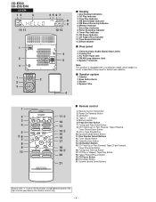
... Button 2 11 3. CD or Tape Stop Button 15 10. Equalizer Mode Select Button 6 7 16 11. CD Random Button 15. Extra Bass Button 21 21. Disc Number Indicators 2. Tape Play Indicator 4. FM Stereo Mode Indicator 5. FM Stereo Receiving Indicator 6. Timer Recording Indicator 9. Timer Play Indicator 10. AC Power Input Jack 4. Speaker Terminals Note: This product is equipped with " " mark in the illustration or highlighted in bold on the right can be operated on the remote control only. - 4 - Woofer 4. CD Button 4. Program Clear Button 4 13 7. Tuner...
... Button 2 11 3. CD or Tape Stop Button 15 10. Equalizer Mode Select Button 6 7 16 11. CD Random Button 15. Extra Bass Button 21 21. Disc Number Indicators 2. Tape Play Indicator 4. FM Stereo Mode Indicator 5. FM Stereo Receiving Indicator 6. Timer Recording Indicator 9. Timer Play Indicator 10. AC Power Input Jack 4. Speaker Terminals Note: This product is equipped with " " mark in the illustration or highlighted in bold on the right can be operated on the remote control only. - 4 - Woofer 4. CD Button 4. Program Clear Button 4 13 7. Tuner...
Service Manual
Page 5
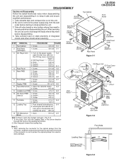
...) x2 6-2 6 Front Panel 1. Screw L1) x1 6-4 2. Inserting the flat head into the hole, push in the arrow direction through the hold on static electricity of the unit. 2. Figure 5-3 Screw B1) x8 5-1 3 CD Player Unit 1. Turn on the power supply, .. 5-2 open the changer manually. (Fig. 5-3) 1. Screw F1) x3 6-1 2. Note 2: 1. After removing the connector for the optical pickup from the...
...) x2 6-2 6 Front Panel 1. Screw L1) x1 6-4 2. Inserting the flat head into the hole, push in the arrow direction through the hold on static electricity of the unit. 2. Figure 5-3 Screw B1) x8 5-1 3 CD Player Unit 1. Turn on the power supply, .. 5-2 open the changer manually. (Fig. 5-3) 1. Screw F1) x3 6-1 2. Note 2: 1. After removing the connector for the optical pickup from the...
Service Manual
Page 10
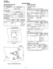
...) *1. Input: Antenna Output: Speaker Terminal • FM IF Signal generator: 10.7 MHz, FM modulated Test Stage Frequency Frequency Display Setting/ Instrument Adjusting Connection Point Tape Motor IF 10.7 MHz 98 MHz T304 *1 (Turn the core of trans- Coverage 87.50 MHz L303 (fL): *1 1.3 V ± 0.1 V TAPE MECHANISM Variable Resistor in motor. 3,000 ± 30 Hz Speaker Terminal (Load resistance: 8 ohms) Test Stage Frequency Frequency Display Setting/ Instrument Adjusting Connection Point FM Band - CD-E500 CD-E55/E44 ADJUSTMENT MECHANISM...
...) *1. Input: Antenna Output: Speaker Terminal • FM IF Signal generator: 10.7 MHz, FM modulated Test Stage Frequency Frequency Display Setting/ Instrument Adjusting Connection Point Tape Motor IF 10.7 MHz 98 MHz T304 *1 (Turn the core of trans- Coverage 87.50 MHz L303 (fL): *1 1.3 V ± 0.1 V TAPE MECHANISM Variable Resistor in motor. 3,000 ± 30 Hz Speaker Terminal (Load resistance: 8 ohms) Test Stage Frequency Frequency Display Setting/ Instrument Adjusting Connection Point FM Band - CD-E500 CD-E55/E44 ADJUSTMENT MECHANISM...
Service Manual
Page 11
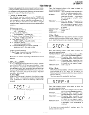
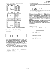
...-by pressing the POWER ON/STAND BY button or return to the ordinary standby mode. Button input diagnosis test mode (TEST06) ........ If focus cannot be pressed.(Focus servo turned on , input is executed. Any other operations are valid. "FF/FWD The pickup slides toward the inner periphery while this mode to take focus. "MEMORY/SET"...... Step 3 Mode While the laser keeps lighting, CD initialization operation flow proceeds...
...-by pressing the POWER ON/STAND BY button or return to the ordinary standby mode. Button input diagnosis test mode (TEST06) ........ If focus cannot be pressed.(Focus servo turned on , input is executed. Any other operations are valid. "FF/FWD The pickup slides toward the inner periphery while this mode to take focus. "MEMORY/SET"...... Step 3 Mode While the laser keeps lighting, CD initialization operation flow proceeds...
Service Manual
Page 12
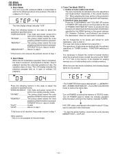
....) The time display always indicates "0:00". CD-E500 CD-E55/E44 4. Outline of ordinary CD playback. 3. Press the following buttons in POWER OFF state and turn on , input is stored in the destinations when the test mode is obtained. (As for frequencies to discard the content of disc, the operation does not stop. Details of tuner test mode Press the "TUNER(BAND)" and "VOLUME UP" buttons in this state to set frequency. 2. However...
....) The time display always indicates "0:00". CD-E500 CD-E55/E44 4. Outline of ordinary CD playback. 3. Press the following buttons in POWER OFF state and turn on , input is stored in the destinations when the test mode is obtained. (As for frequencies to discard the content of disc, the operation does not stop. Details of tuner test mode Press the "TUNER(BAND)" and "VOLUME UP" buttons in this state to set frequency. 2. However...
Service Manual
Page 13
... power is turned off (after WAIT 1 sec), and the mode is obtained, the following procedure to reproduce the timer. 1.Set the current time to 1:00, the timer to ON time 1:05, the function to CD, and volume to the following display lights for one step for 1 sec (WAIT 1 sec inserted). The button operations in (when playback is started) is reproduced. Then pressing the "PLAY" button switches display...
... power is turned off (after WAIT 1 sec), and the mode is obtained, the following procedure to reproduce the timer. 1.Set the current time to 1:00, the timer to ON time 1:05, the function to CD, and volume to the following display lights for one step for 1 sec (WAIT 1 sec inserted). The button operations in (when playback is started) is reproduced. Then pressing the "PLAY" button switches display...
Service Manual
Page 14
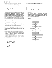
...-IN buttons: REW/PRESET DOWN + CD STOP Since this model is as all the buttons shown below were pressed. PLAY, X-BASS/DEMO, FUNCTION, VOLUME UP/ DOWN, MEMORY/SET, REW, FF, STOP, CD-OPEN/ CLOSE The OK/NG display of keys was pressed after close finish rotate 1 circle - 14 - Button input diagnosis Test Mode (TEST 6) When the test mode is checked whether the "POWER ON/STAND BY" button was not pressed, an error is...
...-IN buttons: REW/PRESET DOWN + CD STOP Since this model is as all the buttons shown below were pressed. PLAY, X-BASS/DEMO, FUNCTION, VOLUME UP/ DOWN, MEMORY/SET, REW, FF, STOP, CD-OPEN/ CLOSE The OK/NG display of keys was pressed after close finish rotate 1 circle - 14 - Button input diagnosis Test Mode (TEST 6) When the test mode is checked whether the "POWER ON/STAND BY" button was not pressed, an error is...
Service Manual
Page 15
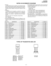
... (ML): Mylar type (P.P.): Polypropylene type • Schematic diagram and Wiring Side of the capacitor without any symbol is used : this model are used: the symbol K means 1000 ohm and the symbol M means 1000 kohm and the resistor without such a symbol is microfarad. DISC 1 X-BASS/DEMO POWER ON/STAND-BY OPEN/CLOSE DISK SKIP VIDEO/AUX TAPE PRESET DOWN PLAY/REPEAT PRESET UP STOP POSITION ON-OFF ON...
... (ML): Mylar type (P.P.): Polypropylene type • Schematic diagram and Wiring Side of the capacitor without any symbol is used : this model are used: the symbol K means 1000 ohm and the symbol M means 1000 kohm and the resistor without such a symbol is microfarad. DISC 1 X-BASS/DEMO POWER ON/STAND-BY OPEN/CLOSE DISK SKIP VIDEO/AUX TAPE PRESET DOWN PLAY/REPEAT PRESET UP STOP POSITION ON-OFF ON...
Service Manual
Page 16
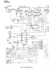
...7 BIAS 8 REC/PLAY 9 REC 10 SOL801 SOLENOID PHOTE INTERRUPTER SWITCHING Q820 Q804 Q817 SOLENOID DRIVER TAPE 1 SW802 INITIALIZE SOL802 SOLENOID PHOTE INTERRUPTER Q809 U_CON5V +B3 Q806 +B2 Q805 Q816 SOLENOID DRIVER CNS803 FROM CNS901 DISPLAY SECTION AUX L R TAPE L R TUNER L R CD L R + + + V V - + DG + Figure 16 BLOCK DIAGRAM (1/4) - 16 - CD-E500 CD-E55/E44 FM ANTENNA AM LOOP ANTENNA B.P.F 3 BF301 2... MPX./AM IF 1 T351 CF352 AM IF 2 4 5 CF351 X351 456 kHz 9 8 17 13 FM MUTE LEVEL VR351 AM OSC OUT AM MIX AM IF GND FM MO/ST IC303 VCC DET VCO L 14 LA1832S FM/AM ...
...7 BIAS 8 REC/PLAY 9 REC 10 SOL801 SOLENOID PHOTE INTERRUPTER SWITCHING Q820 Q804 Q817 SOLENOID DRIVER TAPE 1 SW802 INITIALIZE SOL802 SOLENOID PHOTE INTERRUPTER Q809 U_CON5V +B3 Q806 +B2 Q805 Q816 SOLENOID DRIVER CNS803 FROM CNS901 DISPLAY SECTION AUX L R TAPE L R TUNER L R CD L R + + + V V - + DG + Figure 16 BLOCK DIAGRAM (1/4) - 16 - CD-E500 CD-E55/E44 FM ANTENNA AM LOOP ANTENNA B.P.F 3 BF301 2... MPX./AM IF 1 T351 CF352 AM IF 2 4 5 CF351 X351 456 kHz 9 8 17 13 FM MUTE LEVEL VR351 AM OSC OUT AM MIX AM IF GND FM MO/ST IC303 VCC DET VCO L 14 LA1832S FM/AM ...
Service Manual
Page 22
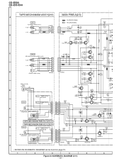
... R807 47K 3 2 Q806 KRC107 M R825 10K 270 H • NOTES ON SCHEMATIC DIAGRAM can be found on page 15. 1 2 3 4 5 6 Figure 22 SCHEMATIC DIAGRAM (3/11) - 22 - CD-E500 CD-E55/E44 Q814 KSC1815 GR C809 82P L(T1) R(T1) L(T2) R(T2) R836 47 TAPE MECHANISM ASS'Y(219) MAIN PWB-A(2/3) A PLAYBACK SIGNAL TAPE 1 RECORD SIGNAL PLAYBACK HEAD (219-7) R-CH L-CH CNW801 1 1 2 2 3 3 TI_R A_GND T1_L C803...
... R807 47K 3 2 Q806 KRC107 M R825 10K 270 H • NOTES ON SCHEMATIC DIAGRAM can be found on page 15. 1 2 3 4 5 6 Figure 22 SCHEMATIC DIAGRAM (3/11) - 22 - CD-E500 CD-E55/E44 Q814 KSC1815 GR C809 82P L(T1) R(T1) L(T2) R(T2) R836 47 TAPE MECHANISM ASS'Y(219) MAIN PWB-A(2/3) A PLAYBACK SIGNAL TAPE 1 RECORD SIGNAL PLAYBACK HEAD (219-7) R-CH L-CH CNW801 1 1 2 2 3 3 TI_R A_GND T1_L C803...
Service Manual
Page 29
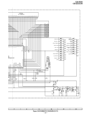
... X-BASS /DEMO R751 1K RX701 GP1UM271 REMOTE SENSOR 123 C709 100/10 C710 0.047 R760 C708 47 100P EQUALIZER VOLUME UP VOLUME DOWN OPEN/CLOSE DISC SKIP VIDEO/AUX TAPE PRESET DOWN PLAY/REPEAT PRESET UP STOP SW719 SW720 SW721 SW703 SW704 SW705 SW706 SW707 SW708 SW709 SW710 R765 75K TUNER (BAND) CD R766 15K REC/PAUSE R767 8.2K MEMORY/SET R768 5.6K TUNING TIME R769 DOWN 3.9K TUNING TIME...
... X-BASS /DEMO R751 1K RX701 GP1UM271 REMOTE SENSOR 123 C709 100/10 C710 0.047 R760 C708 47 100P EQUALIZER VOLUME UP VOLUME DOWN OPEN/CLOSE DISC SKIP VIDEO/AUX TAPE PRESET DOWN PLAY/REPEAT PRESET UP STOP SW719 SW720 SW721 SW703 SW704 SW705 SW706 SW707 SW708 SW709 SW710 R765 75K TUNER (BAND) CD R766 15K REC/PAUSE R767 8.2K MEMORY/SET R768 5.6K TUNING TIME R769 DOWN 3.9K TUNING TIME...
Service Manual
Page 40
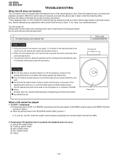
... (5) Others - 40 - Turn the power off any adjustment make certain that the lens is displayed. (1) Check the power to the PICKUP-IN Switch (SW1) position ? CD optical pickup Lens cleaner disc Parts code UDSKA0004AFZZ HOW TO USE 1. If it . 2. All rights reserved. If (1) and (2) are OK, check the system microcomputer (especially the communication line with the eyes. Pressing the CD operation key is taken...
... (5) Others - 40 - Turn the power off any adjustment make certain that the lens is displayed. (1) Check the power to the PICKUP-IN Switch (SW1) position ? CD optical pickup Lens cleaner disc Parts code UDSKA0004AFZZ HOW TO USE 1. If it . 2. All rights reserved. If (1) and (2) are OK, check the system microcomputer (especially the communication line with the eyes. Pressing the CD operation key is taken...
Service Manual
Page 44
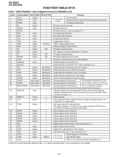
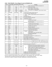
... connected to 0 V, or set them as output Subcode reading clock input terminal. D/A output. 22 SPDO Output ADAVDD/2 Output terminal for Left channel. Terminal functions are identified. The status changes to "H" when the sync signal detected in Reset SLCO Output - Digital system earth terminal. LVDD/2 - Left channel D/A converter Power supply for spindle control. Must be connected to 0 V. 29* DEFECT Output L Defect terminal. 30* V/*P Output H Auto switching monitor output terminal for rough servo phase control. EFMIN Input - RF Output - RF signal input...
... connected to 0 V, or set them as output Subcode reading clock input terminal. D/A output. 22 SPDO Output ADAVDD/2 Output terminal for Left channel. Terminal functions are identified. The status changes to "H" when the sync signal detected in Reset SLCO Output - Digital system earth terminal. LVDD/2 - Left channel D/A converter Power supply for spindle control. Must be connected to 0 V. 29* DEFECT Output L Defect terminal. 30* V/*P Output H Auto switching monitor output terminal for rough servo phase control. EFMIN Input - RF Output - RF signal input...
Service Manual
Page 45
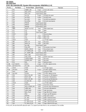
... is not connected to 0 V, or set LOW after first applied power on. 67 DRF Output L Focus detection output port. 68 VDD5 Input - LASER power control signal output port. Chip enable signal input port. 62 CL Input - VCO frequency range adjustment port. 79 LDS Input - Terminal Name Input/Output Setting in Reset Function 44 RVSS 45 RCHO 46 RVDD - Right channel output. or Clock input port for crystal oscillator. and open drain output.) 65 *WRQ Output H Interruption signal output. 66 *RES Input -
... is not connected to 0 V, or set LOW after first applied power on. 67 DRF Output L Focus detection output port. 68 VDD5 Input - LASER power control signal output port. Chip enable signal input port. 62 CL Input - VCO frequency range adjustment port. 79 LDS Input - Terminal Name Input/Output Setting in Reset Function 44 RVSS 45 RCHO 46 RVDD - Right channel output. or Clock input port for crystal oscillator. and open drain output.) 65 *WRQ Output H Interruption signal output. 66 *RES Input -
Service Manual
Page 48
... not connected to GND. 52-67 S20-S35 P5-P20 Output FL(VFD) segment driver. 68 S36 DISC_NO_SW Input Tray disc no. CD-E500 CD-E55/E44 IC701 RH-iX0058SJZZ: System Microcomputer (IX0058SJ) (1/2) Pin No. Port Name Terminal Name Input/Output Function 1 P16 TIMER_LED Output Timer LED control. 2* P17 RDS_DATA Input/Output Open 3* P30 RDS_CLE Input/Output Open 4 P31 CD_CE Output CD DSP CE output. 5 P32 CD_RES Output CD DSP reset. 6 P33 CD_DRF Input CD DRF level detection...
... not connected to GND. 52-67 S20-S35 P5-P20 Output FL(VFD) segment driver. 68 S36 DISC_NO_SW Input Tray disc no. CD-E500 CD-E55/E44 IC701 RH-iX0058SJZZ: System Microcomputer (IX0058SJ) (1/2) Pin No. Port Name Terminal Name Input/Output Function 1 P16 TIMER_LED Output Timer LED control. 2* P17 RDS_DATA Input/Output Open 3* P30 RDS_CLE Input/Output Open 4 P31 CD_CE Output CD DSP CE output. 5 P32 CD_RES Output CD DSP reset. 6 P33 CD_DRF Input CD DRF level detection...
Service Manual
Page 51
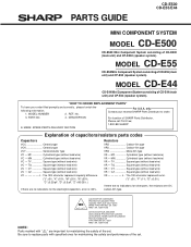
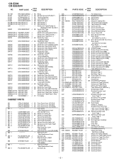
... • • CZ Square type (without lead wire) VC J .. For U.S.A. DESCRIPTION For location of SHARP Parts Distributor, Please call Toll-Free; 1-800-BE-SHARP MARK: SPARE PARTS-DELIVERY SECTION Explanation of CD-E500 (main unit) and CP-E500 (speaker system). Be sure to order. 3. PARTS GUIDE CD-E500 CD-E55/E44 MINI COMPONENT SYSTEM MODEL CD-E500 CD-E500 Mini Component System consisting of capacitors/resistors parts codes Capacitors VCC Ceramic type VCK Ceramic type VCT...
... • • CZ Square type (without lead wire) VC J .. For U.S.A. DESCRIPTION For location of SHARP Parts Distributor, Please call Toll-Free; 1-800-BE-SHARP MARK: SPARE PARTS-DELIVERY SECTION Explanation of CD-E500 (main unit) and CP-E500 (speaker system). Be sure to order. 3. PARTS GUIDE CD-E500 CD-E55/E44 MINI COMPONENT SYSTEM MODEL CD-E500 CD-E500 Mini Component System consisting of capacitors/resistors parts codes Capacitors VCC Ceramic type VCK Ceramic type VCT...
Service Manual
Page 56
...,Cassette,Right AD Cover,Remote Sensor AD Cover,Timer LED AL Rear Panel [CD-E44] Rear Panel [CD-E500 For U.S.A.] AL Rear Panel [CD-E55 For U.S.A.] Rear Panel [CD-E55 For Canada] Rear Panel [CD-E500 For Canada] AE SHARP Badge AD Button,Power [CD-E44/55] AD Button,Power [CD-E500] AF Button,Function [CD-E44/55] AF Button,Function [CD-E500] AF Button,Stop/Play [CD-E44/55] AF Button,Stop/Play [CD-E300] AD Button,X-BASS AF Button,Volume [CD-E44/55] AF Button,Volume [CD-E500] AE Button,Operation [CD-E44/55] AE Button,Operation [CD-E500] Tape Mechanism Ass'y Belt,FF...
...,Cassette,Right AD Cover,Remote Sensor AD Cover,Timer LED AL Rear Panel [CD-E44] Rear Panel [CD-E500 For U.S.A.] AL Rear Panel [CD-E55 For U.S.A.] Rear Panel [CD-E55 For Canada] Rear Panel [CD-E500 For Canada] AE SHARP Badge AD Button,Power [CD-E44/55] AD Button,Power [CD-E500] AF Button,Function [CD-E44/55] AF Button,Function [CD-E500] AF Button,Stop/Play [CD-E44/55] AF Button,Stop/Play [CD-E300] AD Button,X-BASS AF Button,Volume [CD-E44/55] AF Button,Volume [CD-E500] AE Button,Operation [CD-E44/55] AE Button,Operation [CD-E500] Tape Mechanism Ass'y Belt,FF...


