Service Manual
Page 1
.... 00ZUXA260USME FACSIMILE Illustration: UX-A260U MODEL UX-A260 MODEL UX-A260 SELECTION CODE DESTINATION U U.S.A. Chapters 1, 2, 3, 7 and 8 of this manual are omitted because they are important for these parts with " " are partly common to the service manual of CIS unit 5-13 CHAPTER 6. OTHERS [1] Service tools 8-1 [2] Refer to the service manual of the set . SHARP CORPORATION This document has...
.... 00ZUXA260USME FACSIMILE Illustration: UX-A260U MODEL UX-A260 MODEL UX-A260 SELECTION CODE DESTINATION U U.S.A. Chapters 1, 2, 3, 7 and 8 of this manual are omitted because they are important for these parts with " " are partly common to the service manual of CIS unit 5-13 CHAPTER 6. OTHERS [1] Service tools 8-1 [2] Refer to the service manual of the set . SHARP CORPORATION This document has...

Service Manual
Page 3
...10 m) (approx. 30 letter-size pages) Replacement roll (not included): UX-5CR 164 ft. (50 m) roll (one roll yields approx. 150 letter...448 KB (approx. 24 average pages with no documents in individual units. 1 - 1 There may be some deviations from these values in...lb. The performance specifications figures indicated are nominal values of continuous improvement, SHARP reserves the right to 600 mm) Effective scanning width: 8.3" (210... pages max. (letter/A4, 20 lb paper) Recording system: Thermal transfer recording Halftone (grayscale): 64 levels Compression scheme: MH, MR, ...
...10 m) (approx. 30 letter-size pages) Replacement roll (not included): UX-5CR 164 ft. (50 m) roll (one roll yields approx. 150 letter...448 KB (approx. 24 average pages with no documents in individual units. 1 - 1 There may be some deviations from these values in...lb. The performance specifications figures indicated are nominal values of continuous improvement, SHARP reserves the right to 600 mm) Effective scanning width: 8.3" (210... pages max. (letter/A4, 20 lb paper) Recording system: Thermal transfer recording Halftone (grayscale): 64 levels Compression scheme: MH, MR, ...
Service Manual
Page 7
... the UP or DOWN key until the display shows the desired volume level. • Press SPEAKER key again to protect IC's from an overcurrent condition. UX-A260U CHAPTER 2. Output voltage settings POWER SUPPLY PWB (BOTTOM SIDE) TEL/LIU PWB (BOTTOM SIDE) CNPS CNPW CNTH CONTROL PWB (TOP SIDE) CNPN CNLIUA ... The location of output voltage (FACTORY ONLY) 1. KEY: STOP 4. ADJUSTMENTS [1] Adjustments General Since the following adjustments and settings are shown below . Install the power supply unit in the motor drive circuit. SW-B4 DATA No. 3) (step 1) Select "OPTION SETTING".
... the UP or DOWN key until the display shows the desired volume level. • Press SPEAKER key again to protect IC's from an overcurrent condition. UX-A260U CHAPTER 2. Output voltage settings POWER SUPPLY PWB (BOTTOM SIDE) TEL/LIU PWB (BOTTOM SIDE) CNPS CNPW CNTH CONTROL PWB (TOP SIDE) CNPN CNLIUA ... The location of output voltage (FACTORY ONLY) 1. KEY: STOP 4. ADJUSTMENTS [1] Adjustments General Since the following adjustments and settings are shown below . Install the power supply unit in the motor drive circuit. SW-B4 DATA No. 3) (step 1) Select "OPTION SETTING".

Service Manual
Page 10
... are printed. 1. Bit1 - 8 are set . To finish the settings halfway between SW-A1 and SW-O6, press the STOP key. Soft switch content 5. When the unit enters this mode, the check is registered in the entry data send mode. Press FUNCTION 9 8 7 START START DATA No. 1 2 3 45 6 78 S F T SW-A1 = 0 0 0 ...the result of check. Flash memory clear Data in sequence. SW-O6 are set . The soft switch mode is cleared (memory clear). UX-A260U 3. 12. Junk fax number list (*) 6. How to check data conformity. Telephone list data 2. Press key. Press START key ...
... are printed. 1. Bit1 - 8 are set . To finish the settings halfway between SW-A1 and SW-O6, press the STOP key. Soft switch content 5. When the unit enters this mode, the check is registered in the entry data send mode. Press FUNCTION 9 8 7 START START DATA No. 1 2 3 45 6 78 S F T SW-A1 = 0 0 0 ...the result of check. Flash memory clear Data in sequence. SW-O6 are set . The soft switch mode is cleared (memory clear). UX-A260U 3. 12. Junk fax number list (*) 6. How to check data conformity. Telephone list data 2. Press key. Press START key ...

Service Manual
Page 26
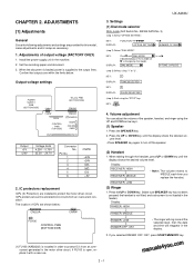
DIAGRAMS [1] Block diagram 4 - 1 manuals4you.com CONTROL PWB UNIT CNPRG FLASH MEMORY 4Mbit DRAM 4Mbit FLASH ROM 2Mbit VBT CLOCK 32.256MHz CLOCK 32.768kHz AMPLIFIER SPEAKER AMPLIFIER 1CHIP FAX ENGINE (SCE214V) CPU I/F ... MOTOR I/F DOCUMENT SENSOR FRONT SENSOR CONTACT IMAGE SENSOR DRIVER PMMOTOR RTC CPU IA(CX20438) FAX MODEM DSP CORE PIO +3.3V SENSOR I/F THERMAL HEAD I/F SIO WATCHDOG TIMER RECORDING PAPER THERMAL HEAD P-IN FILM SENSOR SENSOR FET IMAGING FILM PANEL I/F REGULATOR +24V OPERATION PPAANNEELL LCD STABILIZER HANDSET LINE SURGE PROTECT/ FILTER TEL/LIU...
DIAGRAMS [1] Block diagram 4 - 1 manuals4you.com CONTROL PWB UNIT CNPRG FLASH MEMORY 4Mbit DRAM 4Mbit FLASH ROM 2Mbit VBT CLOCK 32.256MHz CLOCK 32.768kHz AMPLIFIER SPEAKER AMPLIFIER 1CHIP FAX ENGINE (SCE214V) CPU I/F ... MOTOR I/F DOCUMENT SENSOR FRONT SENSOR CONTACT IMAGE SENSOR DRIVER PMMOTOR RTC CPU IA(CX20438) FAX MODEM DSP CORE PIO +3.3V SENSOR I/F THERMAL HEAD I/F SIO WATCHDOG TIMER RECORDING PAPER THERMAL HEAD P-IN FILM SENSOR SENSOR FET IMAGING FILM PANEL I/F REGULATOR +24V OPERATION PPAANNEELL LCD STABILIZER HANDSET LINE SURGE PROTECT/ FILTER TEL/LIU...

Service Manual
Page 27
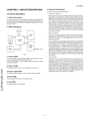
4 - 2 TX/RX MOTOR CAM SW THERMAL HEAD 15 CONTACT IMAGE SENSOR 7 LCD UNIT 14 CNLCD OPERATION PANEL PWB NUIT CNPN-A 6 CNMT 2 CNCSW CNTH CNLIUA CONTROL PWB UNIT CNCIS CNPN CNPW CNSP 3 16 SPEAKER HANDSET 4 CNHJ CNLNJ 14 TEL/LIU PWB UNIT CNLIUA TEL LINE 6 CNPS POWER SUPPLY PWB UNIT AC CORD [2] Wiring diagram UX-A260U
4 - 2 TX/RX MOTOR CAM SW THERMAL HEAD 15 CONTACT IMAGE SENSOR 7 LCD UNIT 14 CNLCD OPERATION PANEL PWB NUIT CNPN-A 6 CNMT 2 CNCSW CNTH CNLIUA CONTROL PWB UNIT CNCIS CNPN CNPW CNSP 3 16 SPEAKER HANDSET 4 CNHJ CNLNJ 14 TEL/LIU PWB UNIT CNLIUA TEL LINE 6 CNPS POWER SUPPLY PWB UNIT AC CORD [2] Wiring diagram UX-A260U
Service Manual
Page 29
... [1] Circuit description 1. This binary data is rotated to move the document down to the thermal head. The data is DMA transferred to receive data. General description The compact design of the control PWB is then converted from...via the 1 chip fax engine (SCE214V) which is sensed via the 1 chip fax engine (SCE214V). CHAPTER 5. UX-A260U 3. Similar to the transmitting operation, the image signal from parallel to serial form to be ready to the...LIU PWB This PWB controls connection of the telephone line to the unit. 3) Power supply PWB This PWB provides voltages of the...
... [1] Circuit description 1. This binary data is rotated to move the document down to the thermal head. The data is DMA transferred to receive data. General description The compact design of the control PWB is then converted from...via the 1 chip fax engine (SCE214V) which is sensed via the 1 chip fax engine (SCE214V). CHAPTER 5. UX-A260U 3. Similar to the transmitting operation, the image signal from parallel to serial form to be ready to the...LIU PWB This PWB controls connection of the telephone line to the unit. 3) Power supply PWB This PWB provides voltages of the...

Service Manual
Page 30
...A timeout circuit controls the power control of control PWB 1. Line times from 50ns to control the whole unit. 1) SCE214V (IC3) : pin-176 QFP (FAX CONTROLLER) 1 chip fax engine has Internal Integrated ...a 500 ms timer that supports NOR, NAND, and Serial NAND-type flash memory. UX-A260U [2] Circuit description of the motors. The ROM stores all the program object code... selectable line times are determined by line basis provide support for thermal or thermal transfer printer support. The SCE214V includes a thermal ADC (TADC) function utilizing a D/A converter and a comparator to...
...A timeout circuit controls the power control of control PWB 1. Line times from 50ns to control the whole unit. 1) SCE214V (IC3) : pin-176 QFP (FAX CONTROLLER) 1 chip fax engine has Internal Integrated ...a 500 ms timer that supports NOR, NAND, and Serial NAND-type flash memory. UX-A260U [2] Circuit description of the motors. The ROM stores all the program object code... selectable line times are determined by line basis provide support for thermal or thermal transfer printer support. The SCE214V includes a thermal ADC (TADC) function utilizing a D/A converter and a comparator to...

Service Manual
Page 39
... Level3 Level4 Level5 OGM playback speaker Level1 volume setting Level2 Level3 Level4 Level5 ICM record speaker Level1 volume setting Level2 Level3 Level4 Level5 1 1 1 0 0 0 1 1 1 1 0 1 0 0 1 1 0 1 1 0 1 1 0 0 0 0 1 0 1 0 1 0 1 0 1 0 0 0 1 1 0 1 1 0 0 0 0 0 1 1 0 1 1 0 0 0 VOL C 1 1 1 0 0 0 1 1 0 1 1 1 1 1 1 0 0 0 0 1 0 0 0 0 5 - 11 UX-A260U manuals4you.com CI detection circuit • CI is detected by the photo coupler which is DTMF signal sending in the existing...
... Level3 Level4 Level5 OGM playback speaker Level1 volume setting Level2 Level3 Level4 Level5 ICM record speaker Level1 volume setting Level2 Level3 Level4 Level5 1 1 1 0 0 0 1 1 1 1 0 1 0 0 1 1 0 1 1 0 1 1 0 0 0 0 1 0 1 0 1 0 1 0 1 0 0 0 1 1 0 1 1 0 0 0 0 0 1 1 0 1 1 0 0 0 VOL C 1 1 1 0 0 0 1 1 0 1 1 1 1 1 1 0 0 0 0 1 0 0 0 0 5 - 11 UX-A260U manuals4you.com CI detection circuit • CI is detected by the photo coupler which is DTMF signal sending in the existing...

Service Manual
Page 41
...circuit through detection of voltage of T1 Subwinding. Block diagram 3.15A/125V AC IN Noise Filter Circuit Rectifying Smoothing Circuit Switching Circuit Control Circuit UX-A260U FUSE 4A/32V +24V +5V Fig. 7 Photo Coupler 2-1. Switching circuit This circuit includes MOS FET Q1 and the gate drive...and the main scanning density of Q1, looking at signal from photo coupler PC1. Control circuit This circuit controls output voltage of CIS unit 1. Waveforms The following clock is supplied from the rectifying/smoothing section is composed of L1 and C1, which puts the original paper...
...circuit through detection of voltage of T1 Subwinding. Block diagram 3.15A/125V AC IN Noise Filter Circuit Rectifying Smoothing Circuit Switching Circuit Control Circuit UX-A260U FUSE 4A/32V +24V +5V Fig. 7 Photo Coupler 2-1. Switching circuit This circuit includes MOS FET Q1 and the gate drive...and the main scanning density of Q1, looking at signal from photo coupler PC1. Control circuit This circuit controls output voltage of CIS unit 1. Waveforms The following clock is supplied from the rectifying/smoothing section is composed of L1 and C1, which puts the original paper...

Service Manual
Page 57
... R4 (10k ) R1 (10k) R5 (10k) R6 (10k) N.M. DG DG DG Note: Since the parts of PWB cannot be supplied, change it as a unit. 3 2 1 4 3 2 1 [4] Operation Panel PWB circuit 1/1 UX-A260U 6 - 16 CNPN-10 SEN0 D CNPN-11 SEN1 CNPN-12 SEN2 CNPN-13 SEN3 CNPN-14 SEN4 CNPN-15 SEN5 CNPN-16 SEN6...
... R4 (10k ) R1 (10k) R5 (10k) R6 (10k) N.M. DG DG DG Note: Since the parts of PWB cannot be supplied, change it as a unit. 3 2 1 4 3 2 1 [4] Operation Panel PWB circuit 1/1 UX-A260U 6 - 16 CNPN-10 SEN0 D CNPN-11 SEN1 CNPN-12 SEN2 CNPN-13 SEN3 CNPN-14 SEN4 CNPN-15 SEN5 CNPN-16 SEN6...

Service Manual
Page 58
UX-A260U Operation panel PWB parts layout (Top side) Operation panel PWB parts layout (Bottom side) Note: Since the parts of PWB cannot be supplied, change it as a unit. 6 - 17 manuals4you.com
UX-A260U Operation panel PWB parts layout (Top side) Operation panel PWB parts layout (Bottom side) Note: Since the parts of PWB cannot be supplied, change it as a unit. 6 - 17 manuals4you.com
Service Manual
Page 60
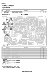
... 8. List NO. Description Refer to the service manual of UX-P100U. 3. PARTS CODE 1 CPWBF3201SCS1 2 PSHEZ3579SCZZ Extension board unit (TEL/LIU PWB) Shading wave memory standard paper DESCRIPTION Extension board unit TEL/LIU PWB TP1 PH2 KA PIN (BROWN) TP3 DG (ORANGE) PH1 C K E A... [1] Service tools 1. Shading paper Refer to the service manual of UX-P100U. [2] IC signal name Refer to the service manual of UX-P100U. [3] Changing the record paper size Refer to the service manual of UX-P100U. PARTS CODE 1 QCNWG471BSCZZ 2 QCNWG206BSCZZ 3 QCNWG202BSCZZ 4 QCNWG205BSCZZ ...
... 8. List NO. Description Refer to the service manual of UX-P100U. 3. PARTS CODE 1 CPWBF3201SCS1 2 PSHEZ3579SCZZ Extension board unit (TEL/LIU PWB) Shading wave memory standard paper DESCRIPTION Extension board unit TEL/LIU PWB TP1 PH2 KA PIN (BROWN) TP3 DG (ORANGE) PH1 C K E A... [1] Service tools 1. Shading paper Refer to the service manual of UX-P100U. [2] IC signal name Refer to the service manual of UX-P100U. [3] Changing the record paper size Refer to the service manual of UX-P100U. PARTS CODE 1 QCNWG471BSCZZ 2 QCNWG206BSCZZ 3 QCNWG202BSCZZ 4 QCNWG205BSCZZ ...
Service Manual
Page 61
CONTENTS 1 Cabinet, etc. 2 Top cover/Sub frame 3 Upper cabinet/Document guide upper 4 Drive unit 5 Packing material & Accessories 6 Control PWB unit 7 TEL/LIU PWB unit 8 Power supply PWB unit 9 Operation panel PWB unit Index Because parts marked with " " are indispensable for the machine safety maintenance and operation, it must be replaced with the parts specific to the product specification. PARTS GUIDE UX-A260U MODEL UX-A260 MODEL UX-A260 SELECTION CODE DESTINATION U U.S.A.
CONTENTS 1 Cabinet, etc. 2 Top cover/Sub frame 3 Upper cabinet/Document guide upper 4 Drive unit 5 Packing material & Accessories 6 Control PWB unit 7 TEL/LIU PWB unit 8 Power supply PWB unit 9 Operation panel PWB unit Index Because parts marked with " " are indispensable for the machine safety maintenance and operation, it must be replaced with the parts specific to the product specification. PARTS GUIDE UX-A260U MODEL UX-A260 MODEL UX-A260 SELECTION CODE DESTINATION U U.S.A.

Service Manual
Page 63
... lever ass'y C PO roller ass'y E Control PWB unit(Within ROM) E TEL/LIU PWB unit E Wire holder(PWB only) C Panel cable C Band...C Back roller C CIS guide,left C CIS guide,right C CIS cable B CIS unit D Lower cabinet C Ink ribbon spool 1 C Ink ribbon spool 2 C Head spring A C...spring C C Head cover C Head guide,left C Head guide,right C Head cable B Thermal head D Front cover C Rubber leg C Bottom plate C Stopper plate C Film sensor lever ...C Panel cable cover C Control PWB cover B AC cord ass'y E Power supply PWB unit D Decoration panel C Static brush C Earth sheet C Up spring C Head spring D ...
... lever ass'y C PO roller ass'y E Control PWB unit(Within ROM) E TEL/LIU PWB unit E Wire holder(PWB only) C Panel cable C Band...C Back roller C CIS guide,left C CIS guide,right C CIS cable B CIS unit D Lower cabinet C Ink ribbon spool 1 C Ink ribbon spool 2 C Head spring A C...spring C C Head cover C Head guide,left C Head guide,right C Head cable B Thermal head D Front cover C Rubber leg C Bottom plate C Stopper plate C Film sensor lever ...C Panel cable cover C Control PWB cover B AC cord ass'y E Power supply PWB unit D Decoration panel C Static brush C Earth sheet C Up spring C Head spring D ...

Service Manual
Page 65
...D C C C E C C C C E C C C C C C C C C D C E Panel case 12 key Start key Function key Operation panel PWB unit Tact switch FRSNS sensor ORGSNS sensor Panel cable LCD unit Separate rubber Separate plate Feed plate Separate spring Feed spring Document guide upper Separate rubber sheet Speed key Function 2 key Decoration panel Screw(2x6...) Operation panel unit - 4 - [3] Upper cabinet/Document guide upper 21 1 901 5 6 9 10 UX-...
...D C C C E C C C C E C C C C C C C C C D C E Panel case 12 key Start key Function key Operation panel PWB unit Tact switch FRSNS sensor ORGSNS sensor Panel cable LCD unit Separate rubber Separate plate Feed plate Separate spring Feed spring Document guide upper Separate rubber sheet Speed key Function 2 key Decoration panel Screw(2x6...) Operation panel unit - 4 - [3] Upper cabinet/Document guide upper 21 1 901 5 6 9 10 UX-...

Service Manual
Page 66
DESCRIPTION manuals4you.com UX-A260U [4] Drive unit B1 22 1 23 7 16 4 11 8 21 14 3 20 9 10 2 13 5 10 15 18 15 6 12 19 17 NO. PARTS CODE [4] Drive unit 1 CGERH2314XH05 2 CLEVP2359XH01 3 CLEVP2360XH01 4 CLEVP2361XH01 5 CLEVP2362XH01 6 LFRM-2226XHZZ 7 LPLTM3190XHZZ 8 MCAMP2028XHZZ 9 MSPRD3298XHZZ 10 NGERH2380XHZZ 11 ...lever ass'y A AD C Planet gear lever ass'y B AD C Planet gear lever ass'y C AD C Planet gear lever ass'y D AQ C Drive unit frame AG C Motor plate AE C Cam AE C Cam hold spring AC C Reduction gear,17/36Z AB C Idler gear,23Z AD C Slip gear AD ...
DESCRIPTION manuals4you.com UX-A260U [4] Drive unit B1 22 1 23 7 16 4 11 8 21 14 3 20 9 10 2 13 5 10 15 18 15 6 12 19 17 NO. PARTS CODE [4] Drive unit 1 CGERH2314XH05 2 CLEVP2359XH01 3 CLEVP2360XH01 4 CLEVP2361XH01 5 CLEVP2362XH01 6 LFRM-2226XHZZ 7 LPLTM3190XHZZ 8 MCAMP2028XHZZ 9 MSPRD3298XHZZ 10 NGERH2380XHZZ 11 ...lever ass'y A AD C Planet gear lever ass'y B AD C Planet gear lever ass'y C AD C Planet gear lever ass'y D AQ C Drive unit frame AG C Motor plate AE C Cam AE C Cam hold spring AC C Reduction gear,17/36Z AB C Idler gear,23Z AD C Slip gear AD ...

Service Manual
Page 71
...(I2164) B Zener diode(HZ9C3) B Zener diode(HZ27) B Zener diode(HZ2C1) B Zener diode(HZ2C1) B Zener diode(HZ2A1) B Zener diode(HZ2A1) E TEL/LIU PWB unit AF AC AF N AC AF AC N AL AK AD N AD N AD N AD AD AD AC AD AD N AD N AD N AD N C Capacitor(275WV 0....C Capacitor(250WV 0.01µF) C Capacitor(1KWV 4700PF) C Base post ass'y(B 2P3-VH) C Connector(IMSA-9110S-06) B Diode(10EDB60) B Diode(10EDB60) B Diode(10EDB60) B Diode(10EDB60) - 10 - UX-A26U [D2] [D3] [D100] [D101] [IC101] [L4] [L8] [PC3] [PC4] [PH1] [PH2] [Q102] [Q103] [Q104] [Q105] [Q106] [R1] [R2] [R7] [...
...(I2164) B Zener diode(HZ9C3) B Zener diode(HZ27) B Zener diode(HZ2C1) B Zener diode(HZ2C1) B Zener diode(HZ2A1) B Zener diode(HZ2A1) E TEL/LIU PWB unit AF AC AF N AC AF AC N AL AK AD N AD N AD N AD AD AD AC AD AD N AD N AD N AD N C Capacitor(275WV 0....C Capacitor(250WV 0.01µF) C Capacitor(1KWV 4700PF) C Base post ass'y(B 2P3-VH) C Connector(IMSA-9110S-06) B Diode(10EDB60) B Diode(10EDB60) B Diode(10EDB60) B Diode(10EDB60) - 10 - UX-A26U [D2] [D3] [D100] [D101] [IC101] [L4] [L8] [PC3] [PC4] [PH1] [PH2] [Q102] [Q103] [Q104] [Q105] [Q106] [R1] [R2] [R7] [...


