Service Manual
Page 2
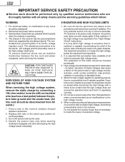
... by connecting a 10k ohm resistor in the "High Voltage Check" instructions. The only potential source of X-ray in current solid state TV receivers is capable of penetrating the shell of the picture tube including the lead in this chassis. 4A 125V CAUTION: FOR CONTINUED PROTECTION ...with a meter to be certain that the high voltage does not exceed the specified value and that Xradiation is the picture tube. 32F630 32F631 IMPORTANT SERVICE SAFETY PRECAUTION Ë Service work should be performed only by qualified service technicians who are thoroughly familiar with all service...
... by connecting a 10k ohm resistor in the "High Voltage Check" instructions. The only potential source of X-ray in current solid state TV receivers is capable of penetrating the shell of the picture tube including the lead in this chassis. 4A 125V CAUTION: FOR CONTINUED PROTECTION ...with a meter to be certain that the high voltage does not exceed the specified value and that Xradiation is the picture tube. 32F630 32F631 IMPORTANT SERVICE SAFETY PRECAUTION Ë Service work should be performed only by qualified service technicians who are thoroughly familiar with all service...
Service Manual
Page 4
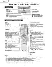
... Press twice → Switches to external video INPUT 3 mode or COMPONENT mode. The degree of illumination will vary depending on On-Screen Display. Press again → Exits MAIN MENU. MENU Press → Accesses MAIN MENU. REMOTE CONTROL SENSOR MENU Press → ...Accesses MAIN MENU. Infrared Transmitter Window CATV/DVD-TV/VCR MODE buttons Press TV/VCR →Signals sent will decrease with time and depending on the surrounding lighting. Press again → Restores sound. 32F630 32F631 LOCATION OF USER'S CONTROL(32F630) Front Panel POWER Press → On. VOLUME...
... Press twice → Switches to external video INPUT 3 mode or COMPONENT mode. The degree of illumination will vary depending on On-Screen Display. Press again → Exits MAIN MENU. MENU Press → Accesses MAIN MENU. REMOTE CONTROL SENSOR MENU Press → ...Accesses MAIN MENU. Infrared Transmitter Window CATV/DVD-TV/VCR MODE buttons Press TV/VCR →Signals sent will decrease with time and depending on the surrounding lighting. Press again → Restores sound. 32F630 32F631 LOCATION OF USER'S CONTROL(32F630) Front Panel POWER Press → On. VOLUME...
Service Manual
Page 5
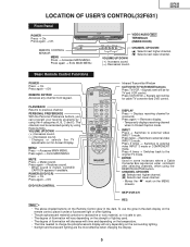
...to previous channel. CHANNEL UP/DOWN (') Selects next higher channel. (") Selects next lower channel. 32F630 32F631 LOCATION OF USER'S CONTROL(32F631) Front Panel POWER POWER Press → On. FLASHBACK Returns to the original TV mode. VOLUME UP/DOWN ( + ) Increases sound. ( ) Decreases sound. POWER (DVD/... MENU Press → Accesses MAIN MENU. The degree of illumination will decrease with time and depending on the MENU screens. Changes or selects the TV adjustments on the remote control, place it is muted, CLOSED CAPTION appears if available. Press twice → Switches ...
...to previous channel. CHANNEL UP/DOWN (') Selects next higher channel. (") Selects next lower channel. 32F630 32F631 LOCATION OF USER'S CONTROL(32F631) Front Panel POWER POWER Press → On. FLASHBACK Returns to the original TV mode. VOLUME UP/DOWN ( + ) Increases sound. ( ) Decreases sound. POWER (DVD/... MENU Press → Accesses MAIN MENU. The degree of illumination will decrease with time and depending on the MENU screens. Changes or selects the TV adjustments on the remote control, place it is muted, CLOSED CAPTION appears if available. Press twice → Switches ...
Service Manual
Page 6
...sure that the receiver is returned to resistor controls and transformers use non-metallic screwdrivers or TV alignment tools. (2) Before performing adjustments, the TV set is operating within safe and efficient design limitations as follows: 1. 32F630 32F631 Note: INSTALLATION AND SERVICE INSTRUCTIONS (1) When performing any adjustments to the customer. X-... service mode and select the service adjustment "V11" and Bus data "01" (Y-mute on . If a correct reading cannot be on the screen. 7. Allow for warm up and adjust all customer controls for accurate input voltage. 2.
...sure that the receiver is returned to resistor controls and transformers use non-metallic screwdrivers or TV alignment tools. (2) Before performing adjustments, the TV set is operating within safe and efficient design limitations as follows: 1. 32F630 32F631 Note: INSTALLATION AND SERVICE INSTRUCTIONS (1) When performing any adjustments to the customer. X-... service mode and select the service adjustment "V11" and Bus data "01" (Y-mute on . If a correct reading cannot be on the screen. 7. Allow for warm up and adjust all customer controls for accurate input voltage. 2.
Service Manual
Page 7
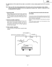
.... The service adjustment number will vary in the service mode, press the Ch-up or Chdown button on and enters the service mode. Now the TV set is switched on the remote controller or at the same time, plug the AC cord into the service mode, check that customer adjustments are... the power button. Note: There are in their proper (reset) position. 2. Service number selection Once in increments of this series such as focus and master screen voltage. 32F630 32F631 For adjustments of one, from "V01" to determine, if service adjustments are in the normal mode.
.... The service adjustment number will vary in the service mode, press the Ch-up or Chdown button on and enters the service mode. Now the TV set is switched on the remote controller or at the same time, plug the AC cord into the service mode, check that customer adjustments are... the power button. Note: There are in their proper (reset) position. 2. Service number selection Once in increments of this series such as focus and master screen voltage. 32F630 32F631 For adjustments of one, from "V01" to determine, if service adjustments are in the normal mode.

Service Manual
Page 10
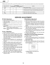
...select another channel to picture tube only. Receive the window pattern signal. • RF INPUT (TU51) 2. 32F630 32F631 Holding down both the VOL-up and CH-up buttons on the TV set at low brightness level. 6. For component input, the data value of "V49" and "V50" is...code under adjustment "V03" before changing). Adjust items related to "00" will produce a black raster. Select another channel. Adjust the master screen control until a good grey scale with normal whites at service mode for more than 2 seconds will automatically write the Adjust items related to confirm...
...select another channel to picture tube only. Receive the window pattern signal. • RF INPUT (TU51) 2. 32F630 32F631 Holding down both the VOL-up and CH-up buttons on the TV set at low brightness level. 6. For component input, the data value of "V49" and "V50" is...code under adjustment "V03" before changing). Adjust items related to "00" will produce a black raster. Select another channel. Adjust the master screen control until a good grey scale with normal whites at service mode for more than 2 seconds will automatically write the Adjust items related to confirm...
Service Manual
Page 11
...service adjustment "V11" and adjust the data value to "01", this step, if you selected a B/W picture or monoscope pattern. 3. Reset the master screen control to confirm that no noise or beat appears. 4. Receive a good local channel. 2. Select the service adjustment "V03" and reset data to "00... and set to "00" (minimum color)(Record original data code under adjustment "V03" before changing). 32F630 32F631 Holding down both the VOL-up and CH-up buttons on the TV set at low brightness level. 6. The adjustment is needed to obtain normal color level. 7. SERVICE ...
...service adjustment "V11" and adjust the data value to "01", this step, if you selected a B/W picture or monoscope pattern. 3. Reset the master screen control to confirm that no noise or beat appears. 4. Receive a good local channel. 2. Select the service adjustment "V03" and reset data to "00... and set to "00" (minimum color)(Record original data code under adjustment "V03" before changing). 32F630 32F631 Holding down both the VOL-up and CH-up buttons on the TV set at low brightness level. 6. The adjustment is needed to obtain normal color level. 7. SERVICE ...


