Service Manual
Page 1
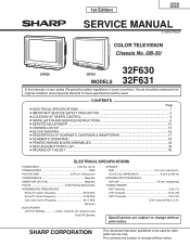
...; ELECTRICAL SPECIFICATIONS ...1 » IMPORTANT SERVICE SAFETY PRECAUTION 2 » LOCATION OF USER'S CONTROL ...4 » INSTALLATION AND SERVICE INSTRUCTIONS 6 » SERVICE ADJUSTMENT ...10 » CHASSIS LAYOUT ...13 » BLOCK DIAGRAM ...15 » DESCRIPTION OF SCHEMATIC DIAGRAMS & WAVEFORMS 17 » SCHEMATIC DIAGRAMS ...18 » PRINTED WIRING BOARD ASSEMBLIES 34 » REPLACEMENT PARTS LIST ...39 » PACKING OF THE SET ...49 ELECTRICAL SPECIFICATIONS POWER INPUT 120V AC, 60 Hz POWER RATING 160W PICTURE SIZE 3074 cm2 (476sq inch) CONVERGENCE...
...; ELECTRICAL SPECIFICATIONS ...1 » IMPORTANT SERVICE SAFETY PRECAUTION 2 » LOCATION OF USER'S CONTROL ...4 » INSTALLATION AND SERVICE INSTRUCTIONS 6 » SERVICE ADJUSTMENT ...10 » CHASSIS LAYOUT ...13 » BLOCK DIAGRAM ...15 » DESCRIPTION OF SCHEMATIC DIAGRAMS & WAVEFORMS 17 » SCHEMATIC DIAGRAMS ...18 » PRINTED WIRING BOARD ASSEMBLIES 34 » REPLACEMENT PARTS LIST ...39 » PACKING OF THE SET ...49 ELECTRICAL SPECIFICATIONS POWER INPUT 120V AC, 60 Hz POWER RATING 160W PICTURE SIZE 3074 cm2 (476sq inch) CONVERGENCE...
Service Manual
Page 2
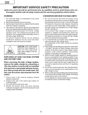
... to the high voltage circuitry. 6. Replace with tube of the same type number for the B+ voltage regulator circuit. When trouble shooting and taking test measurements on a receiver with excessive high voltage, avoid being unnecessarily close to keep the high voltage below the maximum level specified. 2. Disconnect AC power before servicing. 3. The calibration of this meter should always be...
... to the high voltage circuitry. 6. Replace with tube of the same type number for the B+ voltage regulator circuit. When trouble shooting and taking test measurements on a receiver with excessive high voltage, avoid being unnecessarily close to keep the high voltage below the maximum level specified. 2. Disconnect AC power before servicing. 3. The calibration of this meter should always be...
Service Manual
Page 3
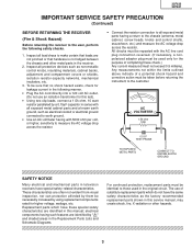
... metal cabinet parts and a known earth ground, such as the factory recommended necessarily increased by using replacement components replacement parts shown in this service manual, may rated for higher voltage, wattage, etc. electrical components having such features are identified in this test). • Using two clip leads, connect a 1.5k ohm, 10 watt resistor paralleled by "å" and shaded areas in the Replacement Parts Lists and...
... metal cabinet parts and a known earth ground, such as the factory recommended necessarily increased by using replacement components replacement parts shown in this service manual, may rated for higher voltage, wattage, etc. electrical components having such features are identified in this test). • Using two clip leads, connect a 1.5k ohm, 10 watt resistor paralleled by "å" and shaded areas in the Replacement Parts Lists and...
Service Manual
Page 4
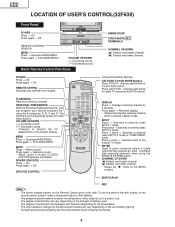
... Closed Caption mode. Press 4 times → Switches back to external video INPUT 1 mode. The degree of illumination will be for TV and VCR control. Press again → Off. Changes or selects the TV adjustments on the Remote Control glow in some instances where a Cable Converter Box requires an enter command after selecting channels, when using these buttons. MUTE Press → Mutes sound. POWER (DVD/VCR) Press → On. Temporarily displays receiving channel when in -the-dark display on the MENU screens. Press 3 times → Switches...
... Closed Caption mode. Press 4 times → Switches back to external video INPUT 1 mode. The degree of illumination will be for TV and VCR control. Press again → Off. Changes or selects the TV adjustments on the Remote Control glow in some instances where a Cable Converter Box requires an enter command after selecting channels, when using these buttons. MUTE Press → Mutes sound. POWER (DVD/VCR) Press → On. Temporarily displays receiving channel when in -the-dark display on the MENU screens. Press 3 times → Switches...
Service Manual
Page 5
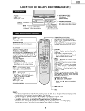
...8594; Displays receiving channel for cable TV converter and DVD control. Temporarily displays receiving channel when in the dark. Press 3 times → Switches to previous channel. The degree of lighting used. VOL + CH PULL-OPEN VIDEO/AUDIO IN 2 TERMINALS (INSIDE DOOR) MENU - CHANNEL UP/DOWN (') Selects next higher channel. (") Selects next lower channel. FLASHBACK Returns to external video INPUT 3 mode or COMPONENT mode. Press again → Exits MAIN MENU. Press again → Restores sound. POWER REMOTE CONTROL SENSOR MENU Press → Accesses MAIN MENU. Press...
...8594; Displays receiving channel for cable TV converter and DVD control. Temporarily displays receiving channel when in the dark. Press 3 times → Switches to previous channel. The degree of lighting used. VOL + CH PULL-OPEN VIDEO/AUDIO IN 2 TERMINALS (INSIDE DOOR) MENU - CHANNEL UP/DOWN (') Selects next higher channel. (") Selects next lower channel. FLASHBACK Returns to external video INPUT 3 mode or COMPONENT mode. Press again → Exits MAIN MENU. Press again → Restores sound. POWER REMOTE CONTROL SENSOR MENU Press → Accesses MAIN MENU. Press...
Service Manual
Page 6
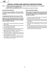
... AC cord and plug the AC cord power on , CRT Cut Off). 4. 32F630 32F631 Note: INSTALLATION AND SERVICE INSTRUCTIONS (1) When performing any adjustments to resistor controls and transformers use non-metallic screwdrivers or TV alignment tools. (2) Before performing adjustments, the TV set is returned to the customer. If the operation of the horizontal oscillator does not stop in test signal. 3. Operate receiver for malfunctioning components. Enter the service mode and select the service adjustment...
... AC cord and plug the AC cord power on , CRT Cut Off). 4. 32F630 32F631 Note: INSTALLATION AND SERVICE INSTRUCTIONS (1) When performing any adjustments to resistor controls and transformers use non-metallic screwdrivers or TV alignment tools. (2) Before performing adjustments, the TV set is returned to the customer. If the operation of the horizontal oscillator does not stop in test signal. 3. Operate receiver for malfunctioning components. Enter the service mode and select the service adjustment...
Service Manual
Page 7
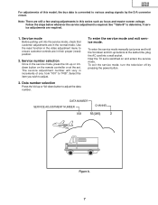
... the normal mode. The service adjustment number will vary in this model, the bus data is converted to various analog signals by pressing the power button. To enter the service mode and exit service mode. DATA NUMBER SERVICE ADJUSTMENT NUMBER CHANNEL V01 55(085) 2 Figure A. 7 Use the reset function in the video adjustment menu to ensure customer controls are still a few analog adjustments in increments of this series such as focus and master screen voltage. Select the item...
... the normal mode. The service adjustment number will vary in this model, the bus data is converted to various analog signals by pressing the power button. To enter the service mode and exit service mode. DATA NUMBER SERVICE ADJUSTMENT NUMBER CHANNEL V01 55(085) 2 Figure A. 7 Use the reset function in the video adjustment menu to ensure customer controls are still a few analog adjustments in increments of this series such as focus and master screen voltage. Select the item...
Service Manual
Page 8
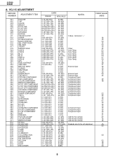
Color Temp. Color Temp. Color Temp. 32F630 32F631 A. VCJ IC ADJUSTMENT SERVICE NUMBER ADJUSTMENT ITEM V01 PICTURE V02 TINT V03 COLOR V05 BRIGHT V06 R CUT-OFF V07 G CUT-OFF V08 B CUT-OFF V09 G/R DRIVE V10 B DRIVE V11 Y-MUTE/V-STOP V12 SHARP V13 DC RESTORATION V14 BLACK STRETCH V15 ABL START POINT V16 ABL GAIN V17 γ POINT V19 ENERGY SAVE V24 LOW-G V25 LOW...
Color Temp. Color Temp. Color Temp. 32F630 32F631 A. VCJ IC ADJUSTMENT SERVICE NUMBER ADJUSTMENT ITEM V01 PICTURE V02 TINT V03 COLOR V05 BRIGHT V06 R CUT-OFF V07 G CUT-OFF V08 B CUT-OFF V09 G/R DRIVE V10 B DRIVE V11 Y-MUTE/V-STOP V12 SHARP V13 DC RESTORATION V14 BLACK STRETCH V15 ABL START POINT V16 ABL GAIN V17 γ POINT V19 ENERGY SAVE V24 LOW-G V25 LOW...
Service Manual
Page 9
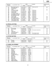
...) NOTES Offset toward D13. 16:9 Format 16:9 Format 16:9 Format 16:9 Format 16:9 Format 16:9 Format 16:9 Format 16:9 Format 16:9 Format 16:9 Format 16:9 Format Offset toward D30 16:9 Format 16:9 Format 16:9 Format B. SPECIAL SETTING SERVICE NUMBER ADJUSTMENT ITEM EX1 FAO VOLUME EX2 CC-POSITION EX3 INT EX4 A-ATT EX5 TUNER data EX6 Think chip-Slice LEVEL EX7 RLY DELAY TIME EX8 ADG ON TIME DATA RANGE INITIAL VALUE NOTES...
...) NOTES Offset toward D13. 16:9 Format 16:9 Format 16:9 Format 16:9 Format 16:9 Format 16:9 Format 16:9 Format 16:9 Format 16:9 Format 16:9 Format 16:9 Format Offset toward D30 16:9 Format 16:9 Format 16:9 Format B. SPECIAL SETTING SERVICE NUMBER ADJUSTMENT ITEM EX1 FAO VOLUME EX2 CC-POSITION EX3 INT EX4 A-ATT EX5 TUNER data EX6 Think chip-Slice LEVEL EX7 RLY DELAY TIME EX8 ADG ON TIME DATA RANGE INITIAL VALUE NOTES...

Service Manual
Page 10
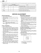
... channel to obtain normal color level. 7. Select the service adjustment "V11" and reset data to obtain normal brightness range. Reset the master screen control to "00". Sub-picture and Sub-Bright Adjustments 1. AB LUMINESCENCE CONFIRMATION A: 95±10cd/m2 B: 1.5±0.5cd/m2 10 Enter the service mode and select the service adjustment "R01". 3. Set the data value to obtain normal color level. For component input, the data value of "V46" red...
... channel to obtain normal color level. 7. Select the service adjustment "V11" and reset data to obtain normal brightness range. Reset the master screen control to "00". Sub-picture and Sub-Bright Adjustments 1. AB LUMINESCENCE CONFIRMATION A: 95±10cd/m2 B: 1.5±0.5cd/m2 10 Enter the service mode and select the service adjustment "R01". 3. Set the data value to obtain normal color level. For component input, the data value of "V46" red...
Service Manual
Page 11
... the service mode to select another channel to "00" (minimum color)(Record original data code under adjustment "V03" before changing). Note 2 : Setting the data to obtain normal color level. Adjust the service adjustments "V06" red, "V07" green and "V08" blue to obtain a good grey scale with normal whites is adjusted to set the luminance as shown in figure "A" and "B" as below respectively. • COMPONENT INPUT 3. Select the service adjustment "V03" and reset...
... the service mode to select another channel to "00" (minimum color)(Record original data code under adjustment "V03" before changing). Note 2 : Setting the data to obtain normal color level. Adjust the service adjustments "V06" red, "V07" green and "V08" blue to obtain a good grey scale with normal whites is adjusted to set the luminance as shown in figure "A" and "B" as below respectively. • COMPONENT INPUT 3. Select the service adjustment "V03" and reset...
Service Manual
Page 12
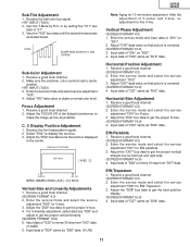
...SCREEN FORMAT 4:3) 2. Receive a good local channel. 2. DISPLAY OF TEXT BOX TEXT BOX | A-B | / 2 A B SPEC INSPECTION:| A-B | / 2 =< 5mm Vertical-Size and Linearity Adjustments 1. Input data of "D34" same as "D02" data. Input data of "D24" same as "D04" data. Adjust "D02" data value so that picture is centered. (SCREEN FORMAT 16:9) 3. EW-Trapezium 1. Enter the service mode and select the service adjustment "D08" for V-size. 3. Make sure the customer color control is centered. (SCREEN FORMAT 16:9) 4. Focus Adjustment 1. C Display Position Adjustment 1. Input...
...SCREEN FORMAT 4:3) 2. Receive a good local channel. 2. DISPLAY OF TEXT BOX TEXT BOX | A-B | / 2 A B SPEC INSPECTION:| A-B | / 2 =< 5mm Vertical-Size and Linearity Adjustments 1. Input data of "D34" same as "D02" data. Input data of "D24" same as "D04" data. Adjust "D02" data value so that picture is centered. (SCREEN FORMAT 16:9) 3. EW-Trapezium 1. Enter the service mode and select the service adjustment "D08" for V-size. 3. Make sure the customer color control is centered. (SCREEN FORMAT 16:9) 4. Focus Adjustment 1. C Display Position Adjustment 1. Input...
Service Manual
Page 13
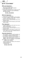
... is displayed almost at the center of IC3001. 3. Feed the following stereo pilot signal to pin (39) of the data range. Enter the service mode and select the service adjustment "M03". 3. for widebando SIGNAL 2 Adj. Vary the "M01" bus data until "OK" appears in position on the screen. SETTING VOLTAGE ADJ spec : 490±10mVrms CHK spec: 490±20mVrms MTS VCO Adjustment 1. 32F630...
... is displayed almost at the center of IC3001. 3. Feed the following stereo pilot signal to pin (39) of the data range. Enter the service mode and select the service adjustment "M03". 3. for widebando SIGNAL 2 Adj. Vary the "M01" bus data until "OK" appears in position on the screen. SETTING VOLTAGE ADJ spec : 490±10mVrms CHK spec: 490±20mVrms MTS VCO Adjustment 1. 32F630...
Service Manual
Page 18
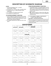
WAVEFORMS 17 This circuit diagram is omitted. (K=kΩ=1000Ω, M=MΩ) 2. 32F630 32F631 DESCRIPTION OF SCHEMATIC DIAGRAM NOTES: 1. The unit of the picture tube depend on a standard gated color bar signal, the tint setting adjusted for normal picture unless otherwise indicated. 2. All capacitors are 1/16 watt, unless otherwise noted. 3. Photographs taken on the tint, color level and picture control. 2. All voltages measured with DVM...
WAVEFORMS 17 This circuit diagram is omitted. (K=kΩ=1000Ω, M=MΩ) 2. 32F630 32F631 DESCRIPTION OF SCHEMATIC DIAGRAM NOTES: 1. The unit of the picture tube depend on a standard gated color bar signal, the tint setting adjusted for normal picture unless otherwise indicated. 2. All capacitors are 1/16 watt, unless otherwise noted. 3. Photographs taken on the tint, color level and picture control. 2. All voltages measured with DVM...
Service Manual
Page 28
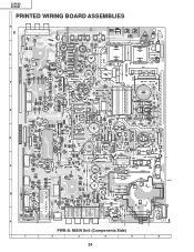
32F630 32F631 PRINTED WIRING BOARD ASSEMBLIES H G F E D C B A PWB-A: MAIN Unit (Components Side) 1 2 3 4 5 6 34
32F630 32F631 PRINTED WIRING BOARD ASSEMBLIES H G F E D C B A PWB-A: MAIN Unit (Components Side) 1 2 3 4 5 6 34
Service Manual
Page 32
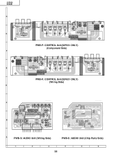
32F630 32F631 H G PWB-F: CONTROL Unit(32F631 ONLY) (Component Side) F E PWB-F: CONTROL Unit(32F631 ONLY) (Wiring Side) D C B A PWB-S: AUDIO Unit (Wiring Side) PWB-S: AUDIO Unit (Chip Parts Side) 1 2 3 4 5 6 38
32F630 32F631 H G PWB-F: CONTROL Unit(32F631 ONLY) (Component Side) F E PWB-F: CONTROL Unit(32F631 ONLY) (Wiring Side) D C B A PWB-S: AUDIO Unit (Wiring Side) PWB-S: AUDIO Unit (Chip Parts Side) 1 2 3 4 5 6 38
Service Manual
Page 33
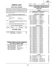
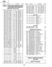
... this service manual may create shock, fire or other hazards. REF. Main Unit(32F630) - PWB-A DUNTKB567WEX8 - Ref. Part No. 5 Description Code PARTS LIST PARTS REPLACEMENT Replacement parts which does no have these special safety characteristics identified in the Replacement Parts Lists and Schematic Diagrams. The use of SHARP Parts Distributor, Please call Toll-Free; 1800-BE-SHARP 5 MARK: SPARE PARTS-DELIVERY SECTION ' MARK: X-RAY RELATED PARTS Ref. DESCRIPTION in this manual ; Part No. 5 Description Code PICTURE TUBE...
... this service manual may create shock, fire or other hazards. REF. Main Unit(32F630) - PWB-A DUNTKB567WEX8 - Ref. Part No. 5 Description Code PARTS LIST PARTS REPLACEMENT Replacement parts which does no have these special safety characteristics identified in the Replacement Parts Lists and Schematic Diagrams. The use of SHARP Parts Distributor, Please call Toll-Free; 1800-BE-SHARP 5 MARK: SPARE PARTS-DELIVERY SECTION ' MARK: X-RAY RELATED PARTS Ref. DESCRIPTION in this manual ; Part No. 5 Description Code PICTURE TUBE...
Service Manual
Page 38
...; X Balun AA MISCELLANEOUS PARTS QPWBFB567WJN2 X Printed Wiring Board AT å ACC701 QACCDA012WJPZ X AC Cord AE FH701 QFSHD1013CEZZ+ X Fuse Holder AA FH702 QFSHD1014CEZZ+ X Fuse Holder AA å F701 QFS-B4023CEZZ X Fuse, 4A/125V AB J904 QJAKGA031WJZZ X Front In Jack(32F630) AC J921 QSOCD0430CEZZ X S-Video Terminal AC J1401 QTANJ1101SEZZ X In Out Jack AF P361 QPLGN0461CEZZA X Plug, 4Pin(S1-4) AB...
...; X Balun AA MISCELLANEOUS PARTS QPWBFB567WJN2 X Printed Wiring Board AT å ACC701 QACCDA012WJPZ X AC Cord AE FH701 QFSHD1013CEZZ+ X Fuse Holder AA FH702 QFSHD1014CEZZ+ X Fuse Holder AA å F701 QFS-B4023CEZZ X Fuse, 4A/125V AB J904 QJAKGA031WJZZ X Front In Jack(32F630) AC J921 QSOCD0430CEZZ X S-Video Terminal AC J1401 QTANJ1101SEZZ X In Out Jack AF P361 QPLGN0461CEZZA X Plug, 4Pin(S1-4) AB...
Service Manual
Page 42
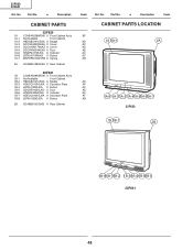
... Cabinet HBDGB3141CESA X Badge HDECQ0105GJKA X Decration Plate JBTN-0128GJKA X Button GDORF0105GJKC X Door HiNDPA433WJSA X Indicator HDECQ0104GJKA X Decration Plate JBTN-0129GJKA X Button 2B GCABB0160GJKB X Rear Cabinet Code Ref. Part No. 5 Description Code CABINET PARTS LOCATION BF AD 1A 1A-1 2A AC AD AE AC AC... AB AD AF AC AE AC AF 1A-8 1A-3 1A-2 1A-41A-51A-61A-7 AB 32F630 1B 1B-1 2B...
... Cabinet HBDGB3141CESA X Badge HDECQ0105GJKA X Decration Plate JBTN-0128GJKA X Button GDORF0105GJKC X Door HiNDPA433WJSA X Indicator HDECQ0104GJKA X Decration Plate JBTN-0129GJKA X Button 2B GCABB0160GJKB X Rear Cabinet Code Ref. Part No. 5 Description Code CABINET PARTS LOCATION BF AD 1A 1A-1 2A AC AD AE AC AC... AB AD AF AC AE AC AF 1A-8 1A-3 1A-2 1A-41A-51A-61A-7 AB 32F630 1B 1B-1 2B...

Service Manual
Page 43
5 Polyethylene Sheet PACKING OF THE SET 5 Polyethylene Bag 32F630 32F631 Operation Manual Infrared R/C Unit 5 Batteries 5Buffer Material FRONT 5 Packing Case 5 MARK : Not replacement items. REAR Use tape to fix the bottom side of packing case. Use 12 staples to fix the top side of packing case. 49
5 Polyethylene Sheet PACKING OF THE SET 5 Polyethylene Bag 32F630 32F631 Operation Manual Infrared R/C Unit 5 Batteries 5Buffer Material FRONT 5 Packing Case 5 MARK : Not replacement items. REAR Use tape to fix the bottom side of packing case. Use 12 staples to fix the top side of packing case. 49


