
Assembly Manual
Page 4
Some parts are packaged on the outside of Contents Hardware 2 Exploded View 4 Parts List 5 Assembly Instructions 6 Important Contact Numbers 19 Attention! CONTENTS Table of the styrofoam packaging. 1 When unpacking the box, please inspect all styrofoam and packaging before discarding.
Some parts are packaged on the outside of Contents Hardware 2 Exploded View 4 Parts List 5 Assembly Instructions 6 Important Contact Numbers 19 Attention! CONTENTS Table of the styrofoam packaging. 1 When unpacking the box, please inspect all styrofoam and packaging before discarding.

Assembly Manual
Page 5
Hardware M8 x 20L HEX HEAD THREAD LOCK (4) M5 x 10L PHILLIPS HEAD (4) M8 WASHER REGULAR (36) M8 x 15L BUTTON HEAD (32) M8 WASHER WIDE (4) M8 x 20L BUTTON HEAD (4) M8 WAVE WASHER (2) Note: Please verify you are missing items, are short quantities, or have all correct parts and quantities before assembling unit. If you have damaged components, please contact Schwinn at 1.800.864.1270. 2
Hardware M8 x 20L HEX HEAD THREAD LOCK (4) M5 x 10L PHILLIPS HEAD (4) M8 WASHER REGULAR (36) M8 x 15L BUTTON HEAD (32) M8 WASHER WIDE (4) M8 x 20L BUTTON HEAD (4) M8 WAVE WASHER (2) Note: Please verify you are missing items, are short quantities, or have all correct parts and quantities before assembling unit. If you have damaged components, please contact Schwinn at 1.800.864.1270. 2

Assembly Manual
Page 6
If you have damaged components, please contact Schwinn at 1.800.864.1270. 3 HARDWARE COTTER PIN (2) STAPLEDTOTHE HARDWARE CARD WRENCHES (2) M8 WASHER LOCKING (40) M8 x 25L FLAT HEAD THREAD LOCK (6) ALLENWRENCH (1) END CAPS (2) Note: Please verify you are missing items, are short quantities, or have all correct parts and quantities before assembling unit.
If you have damaged components, please contact Schwinn at 1.800.864.1270. 3 HARDWARE COTTER PIN (2) STAPLEDTOTHE HARDWARE CARD WRENCHES (2) M8 WASHER LOCKING (40) M8 x 25L FLAT HEAD THREAD LOCK (6) ALLENWRENCH (1) END CAPS (2) Note: Please verify you are missing items, are short quantities, or have all correct parts and quantities before assembling unit.
Assembly Manual
Page 8
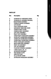
HPAARRTDSWLAISRTE PARTS LIST Ref. Description Qty A SCHWINN 431 HARDWARE CARDS 1 B SCHWINN 431 ASSEMBLY MANUAL 1 C MAIN FRAME Assembly 1 D CONSOLE HANDLE ASSEMBLY 1 E CUP HOLDER 1 F PIVOT SHOULDER COVER 2 G ...Handlebar ASSEMBLY 1 P FRONT STABILIZER ASSEMBLY 1 Q REAR STABILIZER ASSEMBLY 1 R RIGHT Leg ASSEMBLY 1 S LEFT Leg ASSEMBLY 1 T 131/231/431 CONSOLE ASSEMBLY 1 U 110VAC Adaptor, 9V - 1A 1 V extrusion ASSEMBLY 2 W foot mount plate 2 X ARM PIVOT ROD 1 Y 45 mm ROUND COVER 2 Z EXTRUSION...
HPAARRTDSWLAISRTE PARTS LIST Ref. Description Qty A SCHWINN 431 HARDWARE CARDS 1 B SCHWINN 431 ASSEMBLY MANUAL 1 C MAIN FRAME Assembly 1 D CONSOLE HANDLE ASSEMBLY 1 E CUP HOLDER 1 F PIVOT SHOULDER COVER 2 G ...Handlebar ASSEMBLY 1 P FRONT STABILIZER ASSEMBLY 1 Q REAR STABILIZER ASSEMBLY 1 R RIGHT Leg ASSEMBLY 1 S LEFT Leg ASSEMBLY 1 T 131/231/431 CONSOLE ASSEMBLY 1 U 110VAC Adaptor, 9V - 1A 1 V extrusion ASSEMBLY 2 W foot mount plate 2 X ARM PIVOT ROD 1 Y 45 mm ROUND COVER 2 Z EXTRUSION...
Assembly Manual
Page 10
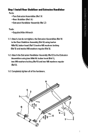
... M8 washers locking (Ref 5) and two M8 washers regular (Ref 3). 1-3 Completely tighten all of the hardware. 5 3 1 Q V Z 3 5 5 1 3 7 ASSEMBLY INSTRUCTIONS Step 1 Install Rear Stabilizer and Extrusion Handlebar Parts: • Two Extrusion Assemblies (Ref.
... M8 washers locking (Ref 5) and two M8 washers regular (Ref 3). 1-3 Completely tighten all of the hardware. 5 3 1 Q V Z 3 5 5 1 3 7 ASSEMBLY INSTRUCTIONS Step 1 Install Rear Stabilizer and Extrusion Handlebar Parts: • Two Extrusion Assemblies (Ref.
Assembly Manual
Page 11
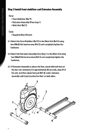
ASSEMBLY INSTRUCTIONS Step 2 Install front stabilizer and Extrusion Assembly Parts: • Front Stabilizer (Ref P) • Extrusion Assembly (From step 1) • Main Unit (Ref C) Tools: • Supplied Allen Wrench 2-1 Attach the Front Stabilizer (Ref P) to the ...
ASSEMBLY INSTRUCTIONS Step 2 Install front stabilizer and Extrusion Assembly Parts: • Front Stabilizer (Ref P) • Extrusion Assembly (From step 1) • Main Unit (Ref C) Tools: • Supplied Allen Wrench 2-1 Attach the Front Stabilizer (Ref P) to the ...
Assembly Manual
Page 12
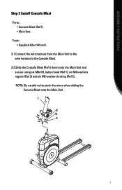
NOTE: Be careful not to the wire harness in the Console Mast. 3-2 Slide the Console Mast (Ref I 3 5 1 9 ASSEMBLY INSTRUCTIONS Step 3 Install Console Mast Parts: • Console Mast (Ref I) • Main Unit Tools: • Supplied Allen Wrench 3-1 Connect the wire harness from the Main Unit to pinch the wires when sliding the Console Mast onto the Main Unit I ) down onto the Main Unit and secure using six M8x15L button head (Ref 1), six M8 washers regular (Ref 3) and six M8 washers locking (Ref 5).
NOTE: Be careful not to the wire harness in the Console Mast. 3-2 Slide the Console Mast (Ref I 3 5 1 9 ASSEMBLY INSTRUCTIONS Step 3 Install Console Mast Parts: • Console Mast (Ref I) • Main Unit Tools: • Supplied Allen Wrench 3-1 Connect the wire harness from the Main Unit to pinch the wires when sliding the Console Mast onto the Main Unit I ) down onto the Main Unit and secure using six M8x15L button head (Ref 1), six M8 washers regular (Ref 3) and six M8 washers locking (Ref 5).
Assembly Manual
Page 13
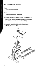
W2 8 D I ) and the Contact Heart Rate Wire (Ref W2) from the Mast (Ref I W1 10 ASSEMBLY INSTRUCTIONS Step 4 Install Console Handlebar Parts: • Console Handlebar (Ref D) Tools: • Supplied Phillips Head Screwdriver 4-1 Feed the Wire Harness (Ref W1) from the Console Handlebar through the hole in the Console Handlebar (Ref D). 4-2 Secure the Console Handlebar to the Mast using four M5x10L phillps screws (Ref 8).
W2 8 D I ) and the Contact Heart Rate Wire (Ref W2) from the Mast (Ref I W1 10 ASSEMBLY INSTRUCTIONS Step 4 Install Console Handlebar Parts: • Console Handlebar (Ref D) Tools: • Supplied Phillips Head Screwdriver 4-1 Feed the Wire Harness (Ref W1) from the Console Handlebar through the hole in the Console Handlebar (Ref D). 4-2 Secure the Console Handlebar to the Mast using four M5x10L phillps screws (Ref 8).
Assembly Manual
Page 14
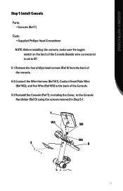
T W3 W1 W2 9 D 11 ASSEMBLY INSTRUCTIONS Step 5 Install Console Parts: • Console (Ref T) Tools: • Supplied Phillips Head Screwdriver NOTE: Before installing the console, make sure the toggle switch on the back of the Console (...
T W3 W1 W2 9 D 11 ASSEMBLY INSTRUCTIONS Step 5 Install Console Parts: • Console (Ref T) Tools: • Supplied Phillips Head Screwdriver NOTE: Before installing the console, make sure the toggle switch on the back of the Console (...
Assembly Manual
Page 15
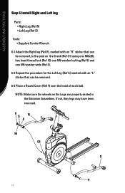
... with an "L" sticker that can be removed. 6-3 Place a Round Cover (Ref Y) over the head of each bolt. ASSEMBLY INSTRUCTIONS Step 6 Install Right and Left leg Parts: • Right Leg (Ref R) • Left Leg (Ref S) Tools: • Supplied Combo Wrench 6-1 Attach the Right leg (Ref R), marked with an "R" sticker that can be...
... with an "L" sticker that can be removed. 6-3 Place a Round Cover (Ref Y) over the head of each bolt. ASSEMBLY INSTRUCTIONS Step 6 Install Right and Left leg Parts: • Right Leg (Ref R) • Left Leg (Ref S) Tools: • Supplied Combo Wrench 6-1 Attach the Right leg (Ref R), marked with an "R" sticker that can be...
Assembly Manual
Page 16
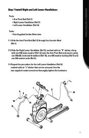
... an "L"sticker that can be removed. Use the two supplied combo wrenches thoroughly tighten the hardware. ASSEMBLY INSTRUCTIONS Step 7 Install Right and Left Lower Handlebars Parts: • Arm Pivot Rod (Ref X) • Right Lower Handlebar (Ref O) • Left Lower Handlebar (Ref N) Tools: • Two Supplied Combo Wrenches 7-1 Slide the Arm Pivot...
... an "L"sticker that can be removed. Use the two supplied combo wrenches thoroughly tighten the hardware. ASSEMBLY INSTRUCTIONS Step 7 Install Right and Left Lower Handlebars Parts: • Arm Pivot Rod (Ref X) • Right Lower Handlebar (Ref O) • Left Lower Handlebar (Ref N) Tools: • Two Supplied Combo Wrenches 7-1 Slide the Arm Pivot...
Assembly Manual
Page 17
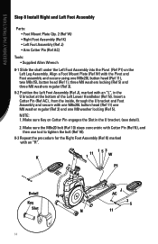
... Left Foot Assembly (Ref J), marked with an "R". K 11 1 153 W P1 Detail Key Slot J AC 3 5 N 11 14 ASSEMBLY INSTRUCTIONS Step 8 Install Right and Left Foot Assembly Parts: • Foot Mount Plate Qty. 2 (Ref W) • Right Foot Assembly (Ref K) • Left Foot Assembly (Ref J) • Arm Cotter Pin (Ref AC) Tools: • Supplied...
... Left Foot Assembly (Ref J), marked with an "R". K 11 1 153 W P1 Detail Key Slot J AC 3 5 N 11 14 ASSEMBLY INSTRUCTIONS Step 8 Install Right and Left Foot Assembly Parts: • Foot Mount Plate Qty. 2 (Ref W) • Right Foot Assembly (Ref K) • Left Foot Assembly (Ref J) • Arm Cotter Pin (Ref AC) Tools: • Supplied...

Assembly Manual
Page 18
ASSEMBLY INSTRUCTIONS Step 9 Install Upper Handlebar Covers and Upper Handlebars Parts: • Upper Handlebar Cover Qty. 2 (Ref G) • Right Upper Handlebar (Ref L) • Left Upper Handlebar (Ref M) Tools: • Supplied Allen Wrench 9-1 At the bottom of ...
ASSEMBLY INSTRUCTIONS Step 9 Install Upper Handlebar Covers and Upper Handlebars Parts: • Upper Handlebar Cover Qty. 2 (Ref G) • Right Upper Handlebar (Ref L) • Left Upper Handlebar (Ref M) Tools: • Supplied Allen Wrench 9-1 At the bottom of ...
Assembly Manual
Page 19
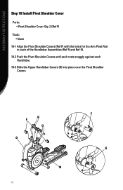
F O 16 F G N ASSEMBLY INSTRUCTIONS Step 10 Install Pivot Shoulder Cover Parts: • Pivot Shoulder Cover Qty. 2 (Ref F) Tools: • None 10-1 Align the Pivot Shoulder Covers (Ref F) with the holes for the Arm Pivot Rod in each of the Handlebar Assemblies (Ref N and Ref O). 10-2 Push the Pivot Shoulder Covers until each rests snuggly against each Handlebar. 10-3 Slide the Upper Handlebar Covers (G) into place over the Pivot Shoulder Covers.
F O 16 F G N ASSEMBLY INSTRUCTIONS Step 10 Install Pivot Shoulder Cover Parts: • Pivot Shoulder Cover Qty. 2 (Ref F) Tools: • None 10-1 Align the Pivot Shoulder Covers (Ref F) with the holes for the Arm Pivot Rod in each of the Handlebar Assemblies (Ref N and Ref O). 10-2 Push the Pivot Shoulder Covers until each rests snuggly against each Handlebar. 10-3 Slide the Upper Handlebar Covers (G) into place over the Pivot Shoulder Covers.
Assembly Manual
Page 20
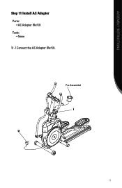
Pre-Assembled I U 17 ASSEMBLY INSTRUCTIONS Step 11 Install AC Adapter Parts: • AC Adapter (Ref U) Tools: • None 11-1 Connect the AC Adapter (Ref U).
Pre-Assembled I U 17 ASSEMBLY INSTRUCTIONS Step 11 Install AC Adapter Parts: • AC Adapter (Ref U) Tools: • None 11-1 Connect the AC Adapter (Ref U).

Owner's Manual
Page 2
...level of your personal fitness goals. So let's get started in an exercise program or are general fitness guidelines. This Schwinn® elliptical trainer should enable you 'll be an efficient, easy and fun way to : p Increase your energy level p Increase...Manual in good shape, this Schwinn® elliptical trainer is designed to be able to a slimmer and healthier body. Take your Schwinn® exercise elliptical trainer. The on Schwinn® craftsmanship and durability as you for making the Schwinn® elliptical trainer a part of fitness. CONGRATULATIONS! Also included...
...level of your personal fitness goals. So let's get started in an exercise program or are general fitness guidelines. This Schwinn® elliptical trainer should enable you 'll be an efficient, easy and fun way to : p Increase your energy level p Increase...Manual in good shape, this Schwinn® elliptical trainer is designed to be able to a slimmer and healthier body. Take your Schwinn® exercise elliptical trainer. The on Schwinn® craftsmanship and durability as you for making the Schwinn® elliptical trainer a part of fitness. CONGRATULATIONS! Also included...
Owner's Manual
Page 4
...stop and consult your physician. 5. Contact Nautilus Customer Service. 6. Care should be taken when mounting and dismounting the Elliptical exercise machine. This machine contains moving parts. Disconnect all Warnings on exercise equipment, and parents and others in a stable position. 10. If, at any ...using this equipment, observe the following definition applies to play on this machine. #!54)/. 3. This machine is designed for loose parts or signs of their respective responsibilities. The pedals should be in charge of children should be aware of wear. Use Caution....
...stop and consult your physician. 5. Contact Nautilus Customer Service. 6. Care should be taken when mounting and dismounting the Elliptical exercise machine. This machine contains moving parts. Disconnect all Warnings on exercise equipment, and parents and others in a stable position. 10. If, at any ...using this equipment, observe the following definition applies to play on this machine. #!54)/. 3. This machine is designed for loose parts or signs of their respective responsibilities. The pedals should be in charge of children should be aware of wear. Use Caution....
Owner's Manual
Page 29
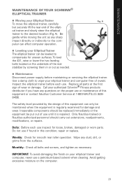
...the 431, raise or lower the two leveling bolts located on your elliptical trainer and computer free of the rear stabilizer by the design of wear or damage. Daily: Before each use until it is regularly examined for loose, broken, damaged or worn parts.... for smooth rear roller operation. Call your authorized Schwinn® Fitness products distributor if you have any dust, dirt, or grime from the surfaces. MAINTENANCE MAINTENANCE OF YOUR SCHWINN® Elliptical trainer n Moving your Elliptical Trainer The elliptical trainer can be leveled to compensate for uneven surfaces...
...the 431, raise or lower the two leveling bolts located on your elliptical trainer and computer free of the rear stabilizer by the design of wear or damage. Daily: Before each use until it is regularly examined for loose, broken, damaged or worn parts.... for smooth rear roller operation. Call your authorized Schwinn® Fitness products distributor if you have any dust, dirt, or grime from the surfaces. MAINTENANCE MAINTENANCE OF YOUR SCHWINN® Elliptical trainer n Moving your Elliptical Trainer The elliptical trainer can be leveled to compensate for uneven surfaces...

Owner's Manual
Page 31
... it in your doctor before beginning any other . Get a physical exam. If you stay on track. Set aside an area or a room in . Make fitness a part of times a day, "I am living a healthier lifestyle by exercising several years or new to an exercise program, be sure to accept new beliefs. Affirmations will...
... it in your doctor before beginning any other . Get a physical exam. If you stay on track. Set aside an area or a room in . Make fitness a part of times a day, "I am living a healthier lifestyle by exercising several years or new to an exercise program, be sure to accept new beliefs. Affirmations will...

Owner's Manual
Page 33
... we perform daily tasks, play or exercise. Also, try Nautilus' new SelectTech® dumbbells, which provide you need complicated equipment or fancy machines. The best part is recommended that you have learned through a range of minutes. For example, you don't have to do everything you a wide variety of dumbbells, or you...
... we perform daily tasks, play or exercise. Also, try Nautilus' new SelectTech® dumbbells, which provide you need complicated equipment or fancy machines. The best part is recommended that you have learned through a range of minutes. For example, you don't have to do everything you a wide variety of dumbbells, or you...


