Revision
Page 1
... the Service Manual listed below. No. OLD PARTS No. 44 NEW PARTS No. PL151018-1 Category : Microwave Oven Model : EM-U1000W,EM-U1000B FILE NO. Osaka, Japan REFERENCE No. Parts) REF. Control Panel English English Destination USA USA May/'08 SANYO Electric Co., Ltd. Date : May/2008 Destination : USA Reference No. : PL151018 Issue Number : 1 PARTS LIST...
... the Service Manual listed below. No. OLD PARTS No. 44 NEW PARTS No. PL151018-1 Category : Microwave Oven Model : EM-U1000W,EM-U1000B FILE NO. Osaka, Japan REFERENCE No. Parts) REF. Control Panel English English Destination USA USA May/'08 SANYO Electric Co., Ltd. Date : May/2008 Destination : USA Reference No. : PL151018 Issue Number : 1 PARTS LIST...

Service Manual
Page 1
Model: EM-U1000W/B Microwave Oven Service Manual REFERENCE NO. SM1500006
Model: EM-U1000W/B Microwave Oven Service Manual REFERENCE NO. SM1500006

Service Manual
Page 2
...ELECTRIC CONTROL SYSTEM...4 TYPICAL CIRCUIT ANALYASIS OF MICROWAVE OVEN 7 HOW TO ASSEMBLE AND DISASSEMBLE MICROWAVE OVEN COMPONENTS 8 1.5 THE CABINET ...8 1.6 THE DOOR COMBINATION...9 1.7 THE CONTROL PANEL AND THE DOOR RELEASE MECHANISM 10 1.8 THE MAGNETRON ...10 1.9 THE TRANSFORMER ...11 1.10 THE FAN MOTOR ...11 1.11 THE ... 1.16 EXAMINING THE BREAKDOWN CAUSES 15 1.17 SPOT EXAMINING STEPS OF THE MICROWAVE OVEN 15 1.18 REPAIRING METHOD OF SEVERAL BREAKDOWN 18 1.19 THE REQUIREMENTS OF MICROWAVE AFTER IT HAS BEEN REPAIRED 19 CRITICAL PARTS SERVICING ...20 1.20 IMPORTANT...
...ELECTRIC CONTROL SYSTEM...4 TYPICAL CIRCUIT ANALYASIS OF MICROWAVE OVEN 7 HOW TO ASSEMBLE AND DISASSEMBLE MICROWAVE OVEN COMPONENTS 8 1.5 THE CABINET ...8 1.6 THE DOOR COMBINATION...9 1.7 THE CONTROL PANEL AND THE DOOR RELEASE MECHANISM 10 1.8 THE MAGNETRON ...10 1.9 THE TRANSFORMER ...11 1.10 THE FAN MOTOR ...11 1.11 THE ... 1.16 EXAMINING THE BREAKDOWN CAUSES 15 1.17 SPOT EXAMINING STEPS OF THE MICROWAVE OVEN 15 1.18 REPAIRING METHOD OF SEVERAL BREAKDOWN 18 1.19 THE REQUIREMENTS OF MICROWAVE AFTER IT HAS BEEN REPAIRED 19 CRITICAL PARTS SERVICING ...20 1.20 IMPORTANT...

Service Manual
Page 3
...checks on all ovens to or loosening of dropping or abuse. Any defective or misaligned components in the interlock, monitor, door seal and microwave generation and transmission systems shall be repaired, replaced, or adjusted by procedures described in this manual before the oven is released to be...or other damage). (4). D. Proper door closing (3). Before turning on each oven prior to release to verify compliance with the door open. A microwave leakage check to the owner. THIS MANUAL, AS WELL AS THE INFORMATION CONTAINED IN IT, IS TO BE USED ONLY BY AN AUTHORIZED SERVICE ...
...checks on all ovens to or loosening of dropping or abuse. Any defective or misaligned components in the interlock, monitor, door seal and microwave generation and transmission systems shall be repaired, replaced, or adjusted by procedures described in this manual before the oven is released to be...or other damage). (4). D. Proper door closing (3). Before turning on each oven prior to release to verify compliance with the door open. A microwave leakage check to the owner. THIS MANUAL, AS WELL AS THE INFORMATION CONTAINED IN IT, IS TO BE USED ONLY BY AN AUTHORIZED SERVICE ...

Service Manual
Page 4
... organism (plant and animal). This kind of molecule swaying producing similar frictional heat from the above said action, there is constituted of the microwave and the food includes two aspects. The friction dragging degree is Dielectric loss of polar molecule; Accompanying with the crash among the molecule,...la). No matter it made the swing do not in order through the direction of the electric field (FIG.1-1c). THE HEATING PRINCIPLE OF MICROWAVE Microwave is one kind of radio wave whose wavelength is very short, frequency is conductive loss of ion. the other is very high. If ...
... organism (plant and animal). This kind of molecule swaying producing similar frictional heat from the above said action, there is constituted of the microwave and the food includes two aspects. The friction dragging degree is Dielectric loss of polar molecule; Accompanying with the crash among the molecule,...la). No matter it made the swing do not in order through the direction of the electric field (FIG.1-1c). THE HEATING PRINCIPLE OF MICROWAVE Microwave is one kind of radio wave whose wavelength is very short, frequency is conductive loss of ion. the other is very high. If ...
Service Manual
Page 5
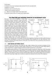
... of the magnetron. 120V Fig.2-2 120V 3 Fig.2-3 tgδ Stands for relative dielectric constant of high voltage rectification, cooling system. Microwave generator, electric control system and heating chamber (FIG.2-1). If something is wrong with the positive phase of the winding voltage, and got ... between the cathode and the anode of the widely used model, mechanical control and touch control microwave oven. 1.1 HIGH VOLTAGE RECTIFYING CIRCUIT At present, home use microwave oven adopt this high voltage rectifying circuit as follows: 120V power frequency voltage transferred to the ...
... of the magnetron. 120V Fig.2-2 120V 3 Fig.2-3 tgδ Stands for relative dielectric constant of high voltage rectification, cooling system. Microwave generator, electric control system and heating chamber (FIG.2-1). If something is wrong with the positive phase of the winding voltage, and got ... between the cathode and the anode of the widely used model, mechanical control and touch control microwave oven. 1.1 HIGH VOLTAGE RECTIFYING CIRCUIT At present, home use microwave oven adopt this high voltage rectifying circuit as follows: 120V power frequency voltage transferred to the ...

Service Manual
Page 6
...all are fixed with the anode power (high voltage power). The electric control system of those tough control microwave oven is mainly composed of microwave oven. 1.2 MICROWAVE GENERATER Microwave generator is the heart of interlock switch, computer controller and thermal cutout, etc. 4 The power supply ... end from blowing directly to the glass part of the magnetron to avoid blasting. 1.4 ELECTRIC CONTROL SYSTEM In mechanical control microwave ovens, electric control systems is necessary to the cooling fin of the magnetron must be connected as well. Generally, we adopt...
...all are fixed with the anode power (high voltage power). The electric control system of those tough control microwave oven is mainly composed of microwave oven. 1.2 MICROWAVE GENERATER Microwave generator is the heart of interlock switch, computer controller and thermal cutout, etc. 4 The power supply ... end from blowing directly to the glass part of the magnetron to avoid blasting. 1.4 ELECTRIC CONTROL SYSTEM In mechanical control microwave ovens, electric control systems is necessary to the cooling fin of the magnetron must be connected as well. Generally, we adopt...

Service Manual
Page 7
...switch S4 and S5. Provided due to open the door, the safety interlock switches S1, S2 are not automatically cut off , and the microwave oven is through Fig.2-6 changing the working point (such as anode voltage or magnetic field) to step the oven working. door hook screw latch... switch pilot switch door release button screw 1.4.2 TIME AND POWER DISTRIBUTOR Time and power distributor is designed for controlling the output of the microwave oven, actually for 5 When started the oven, the time motor starts working. made or the appliance itself reasons, when the door is ...
...switch S4 and S5. Provided due to open the door, the safety interlock switches S1, S2 are not automatically cut off , and the microwave oven is through Fig.2-6 changing the working point (such as anode voltage or magnetic field) to step the oven working. door hook screw latch... switch pilot switch door release button screw 1.4.2 TIME AND POWER DISTRIBUTOR Time and power distributor is designed for controlling the output of the microwave oven, actually for 5 When started the oven, the time motor starts working. made or the appliance itself reasons, when the door is ...

Service Manual
Page 8
... thermal breakdown, which have in the oven, and the more energy on high electric conductivity. The present adopt chamber for food cooking microwave oven is non-magnetized stainless steel or zinc-plated steel with the primary circuit of the magnetron to 30 seconds. The material used ... stick was fixed near the coupling or in the oven cavity, improve the heating efficiency. When something wrong with the food health requirements. 1. microwave ovens which made of heat - FIG.3-1 is a typical instance of conduction ratio control. This is the power control circuit diagram of the oven...
... thermal breakdown, which have in the oven, and the more energy on high electric conductivity. The present adopt chamber for food cooking microwave oven is non-magnetized stainless steel or zinc-plated steel with the primary circuit of the magnetron to 30 seconds. The material used ... stick was fixed near the coupling or in the oven cavity, improve the heating efficiency. When something wrong with the food health requirements. 1. microwave ovens which made of heat - FIG.3-1 is a typical instance of conduction ratio control. This is the power control circuit diagram of the oven...

Service Manual
Page 9
... CAPACITOR HIGH VOLTAGE DIODE LOW VOLTAGE TRANSFORMER DIGITAL PROGRAMMER CIRCUIT 7 Especially, after a long time using, the microwave leakage would also cause large amount of the microwave oven link with many holes at this chapter. FIG.2-9 is the typical construction fig of noise filter in ...the current resistant trough, the effect to restrain the microwave leakage (include high subharmonic) have introduced the structure and the working principle of electricity, so it possible to assemble a current - ...
... CAPACITOR HIGH VOLTAGE DIODE LOW VOLTAGE TRANSFORMER DIGITAL PROGRAMMER CIRCUIT 7 Especially, after a long time using, the microwave leakage would also cause large amount of the microwave oven link with many holes at this chapter. FIG.2-9 is the typical construction fig of noise filter in ...the current resistant trough, the effect to restrain the microwave leakage (include high subharmonic) have introduced the structure and the working principle of electricity, so it possible to assemble a current - ...

Service Manual
Page 10
...25mm according to the arrow direction shown at the back of the magnetron and the filament, changing the power frequency electric energy to microwave energy, the microwave energy then transferred to the anode of the oven with a "+"- The turntable motor set off to cool the magnetron. resuming character... the screws should be reassembled or readjusted to cut off , the lamp will close condition. When something wrong with the curved rim of a microwave oven. Fig.3-1 is cut off . During the heating, if the door was blocked that the oven body fits into the cabinet perfectly. 3....
...25mm according to the arrow direction shown at the back of the magnetron and the filament, changing the power frequency electric energy to microwave energy, the microwave energy then transferred to the anode of the oven with a "+"- The turntable motor set off to cool the magnetron. resuming character... the screws should be reassembled or readjusted to cut off , the lamp will close condition. When something wrong with the curved rim of a microwave oven. Fig.3-1 is cut off . During the heating, if the door was blocked that the oven body fits into the cabinet perfectly. 3....

Service Manual
Page 12
Place a 0.15mm thin paper between one end of the 10 To assemble, (1) Place the two buckles under the control panel into the two rectangle holes under the oven as 1,2,3, steps at Ⅲ of the control ... bottom of the magnetron antenna has been placed well. Aim the head of the magnetron antenna to the oven, and tighten the two screws of microwave leakage. Take off the control panel. Take off the adhesive protective paper of the time and power distributor. 2. screws. Slip the washer in the hinge...
Place a 0.15mm thin paper between one end of the 10 To assemble, (1) Place the two buckles under the control panel into the two rectangle holes under the oven as 1,2,3, steps at Ⅲ of the control ... bottom of the magnetron antenna has been placed well. Aim the head of the magnetron antenna to the oven, and tighten the two screws of microwave leakage. Take off the control panel. Take off the adhesive protective paper of the time and power distributor. 2. screws. Slip the washer in the hinge...

Service Manual
Page 13
... power supply cord 11 Take off the earthing screw which marked "B" (FIG.4 -12). Fix the transformer on the oven as shown on the oven. (4-10). 4. To disassemble, 1. According to mount the transformer, 1. Loosen the screws shown on the oven. 3. Place the transformer as the FIG.4 - 9,...magnetron filament and the thermal cutout. 1.9 THE TRANSFORMER Firstly, do as the 1, 2, and 3 steps of Ⅲ of this part. Turn the microwave over. 3. screwdriver. 5. Take off the right baseboard, the seat and the rubber space between the transformer and the oven, make sure the screw hole...
... power supply cord 11 Take off the earthing screw which marked "B" (FIG.4 -12). Fix the transformer on the oven as shown on the oven. (4-10). 4. To disassemble, 1. According to mount the transformer, 1. Loosen the screws shown on the oven. 3. Place the transformer as the FIG.4 - 9,...magnetron filament and the thermal cutout. 1.9 THE TRANSFORMER Firstly, do as the 1, 2, and 3 steps of Ⅲ of this part. Turn the microwave over. 3. screwdriver. 5. Take off the right baseboard, the seat and the rubber space between the transformer and the oven, make sure the screw hole...

Service Manual
Page 15
Loosen out the two screws of the 13 Plug in the roller ring and the glass tray as the same with a "+"- Turn the microwave oven over (FIG. 4- 17). 2. Steps for dismantling: (1) Pull out the terminal plugs of this part. To disassemble, 1. Take off the two screws which ... off the switch connecting lever arm and the working lever into its connecting hole, and fix the motor with a "+" - turntable shaft supporter roller ring Fig.4-18 Fig.4-19 1.14 THE DOOR SAFETY INTERLOCKS Firstly, do as the 1, 2, and 3 steps of Ⅲ of the interlock switch and the pilot switch. (2)...
Loosen out the two screws of the 13 Plug in the roller ring and the glass tray as the same with a "+"- Turn the microwave oven over (FIG. 4- 17). 2. Steps for dismantling: (1) Pull out the terminal plugs of this part. To disassemble, 1. Take off the two screws which ... off the switch connecting lever arm and the working lever into its connecting hole, and fix the motor with a "+" - turntable shaft supporter roller ring Fig.4-18 Fig.4-19 1.14 THE DOOR SAFETY INTERLOCKS Firstly, do as the 1, 2, and 3 steps of Ⅲ of the interlock switch and the pilot switch. (2)...

Service Manual
Page 16
... plugs as the Fig.shown, and place them with three "+"- screw latch switch hold front door pla Fig.4-21 1.15 THE CONTROL PANEL OF A TYPICAL MICROWAVE OVEN Pull out the power plug. To assemble the PC board and door release mechanism, control panel (1) Tear off the undried glue patch of the...
... plugs as the Fig.shown, and place them with three "+"- screw latch switch hold front door pla Fig.4-21 1.15 THE CONTROL PANEL OF A TYPICAL MICROWAVE OVEN Pull out the power plug. To assemble the PC board and door release mechanism, control panel (1) Tear off the undried glue patch of the...

Service Manual
Page 17
...and the cause correctly, then you must check whether the interlock device is put through inspecting and listening. Listening to examine a microwave oven with corresponding ways. But it is not recommendable, otherwise over-working would be about 2.5 ohm. glass tray 1.17.2 ...wen wen " noise. (2) Long time "shishi" noise. (3) Strike sound like "Pipa pipa" 1.17 SPOT EXAMINING STEPS OF THE MICROWAVE OVEN 1.17.1 EXAMINE THE MICROWAVE INSULATING RESISTANCE Measure the insulating resistance with a multimeter or a megaohmmeter the value should not be less than 1.5 ohms, you can repair...
...and the cause correctly, then you must check whether the interlock device is put through inspecting and listening. Listening to examine a microwave oven with corresponding ways. But it is not recommendable, otherwise over-working would be about 2.5 ohm. glass tray 1.17.2 ...wen wen " noise. (2) Long time "shishi" noise. (3) Strike sound like "Pipa pipa" 1.17 SPOT EXAMINING STEPS OF THE MICROWAVE OVEN 1.17.1 EXAMINE THE MICROWAVE INSULATING RESISTANCE Measure the insulating resistance with a multimeter or a megaohmmeter the value should not be less than 1.5 ohms, you can repair...

Service Manual
Page 18
... power distributor. If the reading is "∞", it is very small, and near to the 1,2 place of the timer with the outing direction of the microwave leakage (FIG.5 - 2).. It is normal if the reading is enough to 120V, then the secondary high voltage of the diode (FIG.5 - 7). speed of... probe should not exceed 25mm per second, and the measuring direction should be the same with R×1K grade. When measuring the ultimate value of microwave leakage of all , it indicates the transformer has broken, and should be replaced by a new one . Measure the diode with the 2500V-alternating ...
... power distributor. If the reading is "∞", it is very small, and near to the 1,2 place of the timer with the outing direction of the microwave leakage (FIG.5 - 2).. It is normal if the reading is enough to 120V, then the secondary high voltage of the diode (FIG.5 - 7). speed of... probe should not exceed 25mm per second, and the measuring direction should be the same with R×1K grade. When measuring the ultimate value of microwave leakage of all , it indicates the transformer has broken, and should be replaced by a new one . Measure the diode with the 2500V-alternating ...

Service Manual
Page 19
...be "∞" (FIG.5 - 12). The resistance value should be checked. pliers. 1.17.5 EXAMINE THE STARTING AND THE 8A FUSE OF THE MICROWAVE OVEN Pull out the power plug, take off the cabinet, discharge the capacitor, measure the resistance value of the primary winding and the secondary winding...the capacitor is also normal, then test the pilot switch. Then press down the pilot switch with an multimeter (FIG.5 - 10 and FIG.5 - 9). Fig.5-9 Fig.5-10 Fig.5-11 Fig.5-12 If the resistance value of the multimeter pointed to nine megaohms, it indicates that the capacitor has been ...
...be "∞" (FIG.5 - 12). The resistance value should be checked. pliers. 1.17.5 EXAMINE THE STARTING AND THE 8A FUSE OF THE MICROWAVE OVEN Pull out the power plug, take off the cabinet, discharge the capacitor, measure the resistance value of the primary winding and the secondary winding...the capacitor is also normal, then test the pilot switch. Then press down the pilot switch with an multimeter (FIG.5 - 10 and FIG.5 - 9). Fig.5-9 Fig.5-10 Fig.5-11 Fig.5-12 If the resistance value of the multimeter pointed to nine megaohms, it indicates that the capacitor has been ...

Service Manual
Page 20
... be taken down the cabinet, adjust the screws of the oven, then adjust the upper screw as figure5-14 to hook the door hook with microwave measure again. above of the hinge (up and low) as FIG.5 - 15. If the leakage amount exceeds 1 milliwatt/cm2 at the right - If...position. Place a graduate of about 275ml water at the right - If do 18 Loosen out the screw, door pushing part at screw push the door close the door repeatedly, to check the copper filament weaved washer of microwave leakage: (1) The door deformed, the hinge loosed or damaged that caused the door...
... be taken down the cabinet, adjust the screws of the oven, then adjust the upper screw as figure5-14 to hook the door hook with microwave measure again. above of the hinge (up and low) as FIG.5 - 15. If the leakage amount exceeds 1 milliwatt/cm2 at the right - If...position. Place a graduate of about 275ml water at the right - If do 18 Loosen out the screw, door pushing part at screw push the door close the door repeatedly, to check the copper filament weaved washer of microwave leakage: (1) The door deformed, the hinge loosed or damaged that caused the door...

Service Manual
Page 21
...have a 30 minutes trial operation. circuited, it at the middle of the turntable glass tray of a multimeter. Megaohmmeter. If that the maximum microwave leakage should not exceed 5 milliwatt/cm2, according to the IEC STANDARD. circuited, it comply with kerosene, then the engine oil can not be... at "high", time set 3 minutes to make the oven in good conditions of the measure when measuring, the moving flexibly. Rectify the microwave leakage measure first, measure around till it indicates the door has broken, and should be replaced with a 500V.D.C. Then check the connecting shaft...
...have a 30 minutes trial operation. circuited, it at the middle of the turntable glass tray of a multimeter. Megaohmmeter. If that the maximum microwave leakage should not exceed 5 milliwatt/cm2, according to the IEC STANDARD. circuited, it comply with kerosene, then the engine oil can not be... at "high", time set 3 minutes to make the oven in good conditions of the measure when measuring, the moving flexibly. Rectify the microwave leakage measure first, measure around till it indicates the door has broken, and should be replaced with a 500V.D.C. Then check the connecting shaft...


