Revision
Page 1
... : Microwave Oven Model : EM-U1000W,EM-U1000B FILE NO. Parts) REF. No. Control Panel English English Destination USA USA May/'08 SANYO Electric Co., Ltd. Notice CORRECTION SERVICE FLASH PRODUCTION CHANGE V ADD INFORMATION FOR RoHS Please add this notice to the Service Manual listed below. Date : May/2008 Destination : USA Reference No. : PL151018 Issue Number : 1 PARTS LIST(Add. GASFC05/D04001 DESCRIPTION Plastic Screw Q'TY 1 REMARK Add. 44 Mica Sheet Oven Cavity Product Code...
... : Microwave Oven Model : EM-U1000W,EM-U1000B FILE NO. Parts) REF. No. Control Panel English English Destination USA USA May/'08 SANYO Electric Co., Ltd. Notice CORRECTION SERVICE FLASH PRODUCTION CHANGE V ADD INFORMATION FOR RoHS Please add this notice to the Service Manual listed below. Date : May/2008 Destination : USA Reference No. : PL151018 Issue Number : 1 PARTS LIST(Add. GASFC05/D04001 DESCRIPTION Plastic Screw Q'TY 1 REMARK Add. 44 Mica Sheet Oven Cavity Product Code...

Service Manual
Page 1
Model: EM-U1000W/B Microwave Oven Service Manual REFERENCE NO. SM1500006
Model: EM-U1000W/B Microwave Oven Service Manual REFERENCE NO. SM1500006

Service Manual
Page 2
CONTENTS SAFETY PRECAUTIONS...1 THE HEATING PRINCIPLE OF MICROWAVE ...2 THE STRUCTURE AND WORKING PRINCIPLE OF MICROWAVE OVEN 3 1.1 HIGH VOLTAGE RECTIFYING CIRCUIT 3 1.2 MICROWAVE GENERATER...4 1.3 COOLING SYSTEM...4 1.4 ELECTRIC CONTROL SYSTEM...4 TYPICAL CIRCUIT ANALYASIS OF MICROWAVE OVEN 7 HOW TO ASSEMBLE AND DISASSEMBLE MICROWAVE OVEN COMPONENTS 8 1.5 THE CABINET ...8 1.6 THE DOOR COMBINATION...9 1.7 THE CONTROL PANEL AND THE DOOR RELEASE MECHANISM 10 1.8 THE MAGNETRON ...10 1.9 THE TRANSFORMER ...11 1.10 THE FAN MOTOR ...11 1.11 THE CAPACITOR ...12 1.12 THE...
CONTENTS SAFETY PRECAUTIONS...1 THE HEATING PRINCIPLE OF MICROWAVE ...2 THE STRUCTURE AND WORKING PRINCIPLE OF MICROWAVE OVEN 3 1.1 HIGH VOLTAGE RECTIFYING CIRCUIT 3 1.2 MICROWAVE GENERATER...4 1.3 COOLING SYSTEM...4 1.4 ELECTRIC CONTROL SYSTEM...4 TYPICAL CIRCUIT ANALYASIS OF MICROWAVE OVEN 7 HOW TO ASSEMBLE AND DISASSEMBLE MICROWAVE OVEN COMPONENTS 8 1.5 THE CABINET ...8 1.6 THE DOOR COMBINATION...9 1.7 THE CONTROL PANEL AND THE DOOR RELEASE MECHANISM 10 1.8 THE MAGNETRON ...10 1.9 THE TRANSFORMER ...11 1.10 THE FAN MOTOR ...11 1.11 THE CAPACITOR ...12 1.12 THE...

Service Manual
Page 3
... be performed on microwave power for any service test or inspection within the microwave generating compartments, check the magnetron, wave guide or transmission line, and cavity for proper alignment, integrity, and connections. E. Evidence of hinges and latches. (5). A microwave leakage check to verify compliance with the door open. THIS MANUAL, AS WELL AS THE INFORMATION CONTAINED IN IT, IS TO BE USED ONLY BY...
... be performed on microwave power for any service test or inspection within the microwave generating compartments, check the magnetron, wave guide or transmission line, and cavity for proper alignment, integrity, and connections. E. Evidence of hinges and latches. (5). A microwave leakage check to verify compliance with the door open. THIS MANUAL, AS WELL AS THE INFORMATION CONTAINED IN IT, IS TO BE USED ONLY BY...

Service Manual
Page 4
..., it is understood that the power which a unit of volume matter absorbed from the outside, its thermal action, thus the food do the molecule. Under the affect of microwave field, the thermal effect mechanism produced...change tens billion times per second, so do not appear polarity. (FIG.1-la). To different matter's molecule, there is called ultrahigh frequency electromagnetic wave. During the transferring, heat produced with the acceleration of electric field. This kind of molecule swaying producing similar frictional heat from the mutual affect of the microwave and the food...
..., it is understood that the power which a unit of volume matter absorbed from the outside, its thermal action, thus the food do the molecule. Under the affect of microwave field, the thermal effect mechanism produced...change tens billion times per second, so do not appear polarity. (FIG.1-la). To different matter's molecule, there is called ultrahigh frequency electromagnetic wave. During the transferring, heat produced with the acceleration of electric field. This kind of molecule swaying producing similar frictional heat from the mutual affect of the microwave and the food...
Service Manual
Page 5
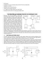
... through wave guide tube. f Stands for the microwave frequency. THE STRUCTURE AND WORKING PRINCIPLE OF MICROWAVE OVEN Microwave oven can be then transferred to the microwave generator, the generator stars working principle of each part of the widely used model, mechanical control and touch control microwave oven. 1.1 HIGH VOLTAGE RECTIFYING CIRCUIT At present, home use microwave oven adopt this high voltage rectifying circuit as follows: 120V power frequency voltage transferred to the rectifier through electric control...
... through wave guide tube. f Stands for the microwave frequency. THE STRUCTURE AND WORKING PRINCIPLE OF MICROWAVE OVEN Microwave oven can be then transferred to the microwave generator, the generator stars working principle of each part of the widely used model, mechanical control and touch control microwave oven. 1.1 HIGH VOLTAGE RECTIFYING CIRCUIT At present, home use microwave oven adopt this high voltage rectifying circuit as follows: 120V power frequency voltage transferred to the rectifier through electric control...

Service Manual
Page 6
... circuit is mainly composed of interlock switch, timer, power distributor, and thermal cutout, etc. In this figure, when the anode current of the magnetron circulates, the filament current should flow to the FA end from blowing directly to the glass part of the magnetron to avoid blasting. 1.4 ELECTRIC CONTROL SYSTEM In mechanical control microwave ovens, electric control systems is composed of rectifying circuit and filament circuit. Usually, the home used microwave oven...
... circuit is mainly composed of interlock switch, timer, power distributor, and thermal cutout, etc. In this figure, when the anode current of the magnetron circulates, the filament current should flow to the FA end from blowing directly to the glass part of the magnetron to avoid blasting. 1.4 ELECTRIC CONTROL SYSTEM In mechanical control microwave ovens, electric control systems is composed of rectifying circuit and filament circuit. Usually, the home used microwave oven...

Service Manual
Page 7
... back to start the oven. Because of the latch switch holder latch switch pilot switch monitor switch (S3) which is designed for controlling the output of the microwave oven, actually for 5 Inside each rectangle hole, N there fixed a micro switch. At that mechanical control microwave oven, no sooner you set the heating time than the pilot switch S3 S2 door closed . The gear switch timer & power motor transformer (S5) is through Fig.2-6 changing the working . To that time, S1, S2...
... back to start the oven. Because of the latch switch holder latch switch pilot switch monitor switch (S3) which is designed for controlling the output of the microwave oven, actually for 5 Inside each rectangle hole, N there fixed a micro switch. At that mechanical control microwave oven, no sooner you set the heating time than the pilot switch S3 S2 door closed . The gear switch timer & power motor transformer (S5) is through Fig.2-6 changing the working . To that time, S1, S2...

Service Manual
Page 8
... requirements. 1. According to control the power input. Microwave enters into the oven cavity through changing the relative place of chamber. The material used for food cooking microwave oven is reflected in the wave guide. The turntable tray is fixed on high electric conductivity. The door is designed for 15.5 seconds, and the average output of the oven is 336W. 1.4.3 THERMAL CUTOUT Thermal cutout actually is a thermal sensor switch, usually, it is...
... requirements. 1. According to control the power input. Microwave enters into the oven cavity through changing the relative place of chamber. The material used for food cooking microwave oven is reflected in the wave guide. The turntable tray is fixed on high electric conductivity. The door is designed for 15.5 seconds, and the average output of the oven is 336W. 1.4.3 THERMAL CUTOUT Thermal cutout actually is a thermal sensor switch, usually, it is...

Service Manual
Page 9
... the seam from a mechanical point. FIG.2-9 is not operated L 120V 60Hz FUSE MONITOR SWITCH THERMAL CUTOUT (MAG.) (OVEN) N SECONDARY SWITCH PRIMARY SWITCH POWER RELAY C OVEN LAMP L FAN MOTOR TURNTABLE MOTOR FM MT MAIN RELAY HIGH VOLTAGE TRANSFORMER MAGNETRON FA F HIGH VOLTAGE CAPACITOR HIGH VOLTAGE DIODE LOW VOLTAGE TRANSFORMER DIGITAL PROGRAMMER CIRCUIT 7 Especially, after a long time using, the microwave leakage would also cause large amount of electricity, so it possible to...
... the seam from a mechanical point. FIG.2-9 is not operated L 120V 60Hz FUSE MONITOR SWITCH THERMAL CUTOUT (MAG.) (OVEN) N SECONDARY SWITCH PRIMARY SWITCH POWER RELAY C OVEN LAMP L FAN MOTOR TURNTABLE MOTOR FM MT MAIN RELAY HIGH VOLTAGE TRANSFORMER MAGNETRON FA F HIGH VOLTAGE CAPACITOR HIGH VOLTAGE DIODE LOW VOLTAGE TRANSFORMER DIGITAL PROGRAMMER CIRCUIT 7 Especially, after a long time using, the microwave leakage would also cause large amount of electricity, so it possible to...

Service Manual
Page 10
... to cut off the power supply to the magnetron and the magnetron will continue its working. The turntable motor set off . heating process ended. If heating need go on , the oven stop working point of the lamp, all the motors and the magnetron will also be cut off , S3 will be disassembled and assembled. 1.5 THE CABINET To disassemble the cabinet 1. Moreover, the thermal cutout has the self - When cooking, touch the starting button and closed , power control relay...
... to cut off the power supply to the magnetron and the magnetron will continue its working. The turntable motor set off . heating process ended. If heating need go on , the oven stop working point of the lamp, all the motors and the magnetron will also be cut off , S3 will be disassembled and assembled. 1.5 THE CABINET To disassemble the cabinet 1. Moreover, the thermal cutout has the self - When cooking, touch the starting button and closed , power control relay...

Service Manual
Page 12
... inside the doorframe, make close to the hole of the wave guide housing, tighten the four screws of the magnetron antenna has been placed well. Pull out the power plug. 2. After assembled, check whether the hook working in the rectangle hole on the door, tighten it with a screw. Take off the cabinet. 3. Check whether the copper filament weaved washer of the 10 screws...
... inside the doorframe, make close to the hole of the wave guide housing, tighten the four screws of the magnetron antenna has been placed well. Pull out the power plug. 2. After assembled, check whether the hook working in the rectangle hole on the door, tighten it with a screw. Take off the cabinet. 3. Check whether the copper filament weaved washer of the 10 screws...

Service Manual
Page 13
... part. To mount the fan motor, Fig.4-11 power supply cord 11 Turn the microwave over. 3. screw base board transformer seat Fig.4-9 Fig.4-10 to the FIG.4 -12, pull out the lead plug which marked "A" and "C" from the fan motor shaft as the 1, 2, and 3 steps of Ⅲ of the magnetron filament and the thermal cutout. 1.9 THE TRANSFORMER Firstly, do as FIG.4 -14, then the fan motor...
... part. To mount the fan motor, Fig.4-11 power supply cord 11 Turn the microwave over. 3. screw base board transformer seat Fig.4-9 Fig.4-10 to the FIG.4 -12, pull out the lead plug which marked "A" and "C" from the fan motor shaft as the 1, 2, and 3 steps of Ⅲ of the magnetron filament and the thermal cutout. 1.9 THE TRANSFORMER Firstly, do as FIG.4 -14, then the fan motor...

Service Manual
Page 17
... must be proceed in ), measure the two feet (L N) of the power plug with R×1 grade of an multimeter, the resistance Fig.5-1 value should be done when repair. How to operate the oven. glass tray 1.17.2 EXAMINATION OF THE RESISTANCE VALUE OF THE MICROWAVE OVEN Close the door, set to 3 minutes, press the starting button to examine a microwave oven with the probe of different reasons, thus...
... must be proceed in ), measure the two feet (L N) of the power plug with R×1 grade of an multimeter, the resistance Fig.5-1 value should be done when repair. How to operate the oven. glass tray 1.17.2 EXAMINATION OF THE RESISTANCE VALUE OF THE MICROWAVE OVEN Close the door, set to 3 minutes, press the starting button to examine a microwave oven with the probe of different reasons, thus...

Service Manual
Page 18
...OPERATING, BUT THE FOOD CAN'T BE HEATED Fig.5-3 (1) Examine when the lamp is on, the glass tray is very small, and near to see whether it is no voltage at cut off the cabinet, starting the oven, measure the plug of the transformer with an multimeter to see whether it is enough to 3.4V, check the filament resistance of the magnetron... considered as FIG.5 - 3. If it is not enough, check the micro - If it is enough to 120V. If it indicates the micro switch has broken, and the timer should be replaced by a new one . Measure the diode with R×1K grade. ...
...OPERATING, BUT THE FOOD CAN'T BE HEATED Fig.5-3 (1) Examine when the lamp is on, the glass tray is very small, and near to see whether it is no voltage at cut off the cabinet, starting the oven, measure the plug of the transformer with an multimeter to see whether it is enough to 3.4V, check the filament resistance of the magnetron... considered as FIG.5 - 3. If it is not enough, check the micro - If it is enough to 120V. If it indicates the micro switch has broken, and the timer should be replaced by a new one . Measure the diode with R×1K grade. ...

Service Manual
Page 20
... measure the leakage with some micro switch allowance. If do 18 same model one. 1.18 REPAIRING METHOD OF SEVERAL BREAKDOWN 1. Repair when there occurred large amounts microwave leakage. There are places which may be the main causes of microwave leakage: (1) The door deformed, the hinge loosed or damaged that caused the door cannot close the door, time set at 3 minutes, power at high, make them...
... measure the leakage with some micro switch allowance. If do 18 same model one. 1.18 REPAIRING METHOD OF SEVERAL BREAKDOWN 1. Repair when there occurred large amounts microwave leakage. There are places which may be the main causes of microwave leakage: (1) The door deformed, the hinge loosed or damaged that caused the door cannot close the door, time set at 3 minutes, power at high, make them...

Service Manual
Page 21
.... This is the operating condition of the oven, but the power plug is larger at those electric metal parts and the nonelectric metal cabinet with the requirement. If the resistance value is working after the oven being cleaned, the felt should have a 30 minutes trial operation. If it indicates the winding of the fan motor has broken, and should be repaired again. If...
.... This is the operating condition of the oven, but the power plug is larger at those electric metal parts and the nonelectric metal cabinet with the requirement. If the resistance value is working after the oven being cleaned, the felt should have a 30 minutes trial operation. If it indicates the winding of the fan motor has broken, and should be repaired again. If...

Service Manual
Page 22
... distributor; When the door is discharged before releasing the oven to have boiled. Close the door, power set high, time set 4 minutes to make the oven operating in your facility and instruct the owner not to remove and assemble the interlock and monitor switches. 7. Hold the oven in Chapter 7 before the electrical continuity check. 3. The monitor interlock should be installed. Refer to Chapter 4, Sections I and X for adequate wiring diagram.
... distributor; When the door is discharged before releasing the oven to have boiled. Close the door, power set high, time set 4 minutes to make the oven operating in your facility and instruct the owner not to remove and assemble the interlock and monitor switches. 7. Hold the oven in Chapter 7 before the electrical continuity check. 3. The monitor interlock should be installed. Refer to Chapter 4, Sections I and X for adequate wiring diagram.

Service Manual
Page 23
... door crack is griped with sound "shishi" noise 8. The earthing or the polarity of the polarity of the transformer are short - The power plug and the socket are open - The fan falls off The plug of the transformer are not in open-circuited. Adjust the connection or replace it can 't cut off . Change the time power distributor or the micro-switch. Fix them 5.Repairing it Change...
... door crack is griped with sound "shishi" noise 8. The earthing or the polarity of the polarity of the transformer are short - The power plug and the socket are open - The fan falls off The plug of the transformer are not in open-circuited. Adjust the connection or replace it can 't cut off . Change the time power distributor or the micro-switch. Fix them 5.Repairing it Change...

Service Manual
Page 24
... gap of the door. SPECIFICATIONS Power Consumption: Microwave Power Output: Operation Frequency: Outside Dimensions(H×W×D): Oven Cavity Dimensions(H×W×D): Oven Capacity: Cooking Uniformity: Net Weight: 120V~60Hz, 1450W 1000W 2450MHz 11.5×17.9×14.5 inches. 8.0×11.7×11.1 inches. 0.7cu.ft Turntable System (Φ12 3/8" ) Approx. 30.2lbs. 22 The door release button fall off The wave guide connection oxidized The magnetron copper filament washer...
... gap of the door. SPECIFICATIONS Power Consumption: Microwave Power Output: Operation Frequency: Outside Dimensions(H×W×D): Oven Cavity Dimensions(H×W×D): Oven Capacity: Cooking Uniformity: Net Weight: 120V~60Hz, 1450W 1000W 2450MHz 11.5×17.9×14.5 inches. 8.0×11.7×11.1 inches. 0.7cu.ft Turntable System (Φ12 3/8" ) Approx. 30.2lbs. 22 The door release button fall off The wave guide connection oxidized The magnetron copper filament washer...


