
User Manual
Page 5
... 8. The data buffer allows the unit to change without notice. Different print densities can be selected by using your new SRP-350. ※ NOTE The socket-outlet shall be near the equipment and it 's original size. 7. Characters can be scaled...Ethernet (IFA-E TYPE), RS-232 + USB (IFA-SU TYPE). 4. Rev. 1.02 - 5 - Bar code printing is possible by DIP switches. Low noise thermal printing. 3. ■ Introduction SRP-350 The SRP-350 Roll Printer are designed for use with electronic instruments such as follows: 1. Peripheral units drive circuit enables control of the...
... 8. The data buffer allows the unit to change without notice. Different print densities can be selected by using your new SRP-350. ※ NOTE The socket-outlet shall be near the equipment and it 's original size. 7. Characters can be scaled...Ethernet (IFA-E TYPE), RS-232 + USB (IFA-SU TYPE). 4. Rev. 1.02 - 5 - Bar code printing is possible by DIP switches. Low noise thermal printing. 3. ■ Introduction SRP-350 The SRP-350 Roll Printer are designed for use with electronic instruments such as follows: 1. Peripheral units drive circuit enables control of the...

User Manual
Page 6
......21 Rev. 1.02 - 6 - Specification ...20 5. ■ Table of Contents SRP-350 1. Hexadecimal Dumping 19 4. Setting Up the Printer 7 1-1 Unpacking...7 1-2 Connecting the Cables 8 1-2-1 Serial Interface (RS-232C 8 1-2-2 Serial Interface (RS-485 9 1-2-3 Parallel Interface (IEEE1284 10 1-2-4 USB Interface 11 1-3 Connecting the Drawer 11 1-4 Setting the Dip Switches 12 1-4-1 Serial Interface 12 1-4-2 Parallel & USB Interface 13 1-5 Installing or...
......21 Rev. 1.02 - 6 - Specification ...20 5. ■ Table of Contents SRP-350 1. Hexadecimal Dumping 19 4. Setting Up the Printer 7 1-1 Unpacking...7 1-2 Connecting the Cables 8 1-2-1 Serial Interface (RS-232C 8 1-2-2 Serial Interface (RS-485 9 1-2-3 Parallel Interface (IEEE1284 10 1-2-4 USB Interface 11 1-3 Connecting the Drawer 11 1-4 Setting the Dip Switches 12 1-4-1 Serial Interface 12 1-4-2 Parallel & USB Interface 13 1-5 Installing or...

User Manual
Page 8
...SRP-350 1-2 Connecting the Cables You can connect up the three cables to the connector panel on the back of the printer, which is shown below: ※ NOTE Before connecting any of the cables, make sure that both the printer... and the host are turned off. 1-2-1 Serial Interface (RS-232C) IFA-S TYPE ON Interface connector Drawer kick-out Power supply connector connector ※ When the Dip Switch is ... Set Ready Signal Ground Data Terminal Ready They all connect to the printer. PRINTER SIDE (25P) HOST SIDE (25P) PRINTER SIDE (25P) HOST SIDE (9P) Pin No. 1 2 3 4 5...
...SRP-350 1-2 Connecting the Cables You can connect up the three cables to the connector panel on the back of the printer, which is shown below: ※ NOTE Before connecting any of the cables, make sure that both the printer... and the host are turned off. 1-2-1 Serial Interface (RS-232C) IFA-S TYPE ON Interface connector Drawer kick-out Power supply connector connector ※ When the Dip Switch is ... Set Ready Signal Ground Data Terminal Ready They all connect to the printer. PRINTER SIDE (25P) HOST SIDE (25P) PRINTER SIDE (25P) HOST SIDE (9P) Pin No. 1 2 3 4 5...

User Manual
Page 9
1-2-2 Serial Interface (RS-485) SRP-350 IFA-SF TYPE ON Interface connector Drawer kick-out Power supply connector connector ※ When the Dip Switch is "ON" on the Serial Interface Board, DTR and RTS are connected each other. PRINTER SIDE HOST SIDE Pin No. 1 2 3 4 5 7 8 9 10 11 Signal name FGND SD2 SD1 RD2 RD1 SGND DR2 DR1 CS2 CS1 Direction - Output Input Function Frame Ground Send Data Receive Data Signal Ground Same as DTR(RS-232) Same as DSR(RS-232) Rev. 1.02 - 9 - Output Output Input Input -
1-2-2 Serial Interface (RS-485) SRP-350 IFA-SF TYPE ON Interface connector Drawer kick-out Power supply connector connector ※ When the Dip Switch is "ON" on the Serial Interface Board, DTR and RTS are connected each other. PRINTER SIDE HOST SIDE Pin No. 1 2 3 4 5 7 8 9 10 11 Signal name FGND SD2 SD1 RD2 RD1 SGND DR2 DR1 CS2 CS1 Direction - Output Input Function Frame Ground Send Data Receive Data Signal Ground Same as DTR(RS-232) Same as DSR(RS-232) Rev. 1.02 - 9 - Output Output Input Input -
User Manual
Page 12
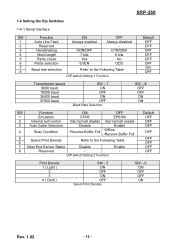
... ) 2 3 4 ( Dark ) SW - 5 ON OFF ON OFF Select Print Density SW - 6 ON OFF OFF ON Rev. 1.02 - 12 - SRP-350 1-4 Setting the Dip Switches 1-4-1 Serial Interface SW Function ON OFF 1 Auto Line Feed Always enabled Always disabled 2 Reserved - - 3 Handshaking XON/OFF DTR/DSR 4 Word length 7 bits ...8 bits 5 Parity check Yes No 6 Parity selection EVEN ODD 7 8 Baud rate selection Refer to the Following Table DIP switch Setting 1 Function Default OFF OFF OFF OFF OFF OFF ON OFF Transmission speed 9600 baud 19200 baud 38400 baud 57600 baud SW - 7 ...
... ) 2 3 4 ( Dark ) SW - 5 ON OFF ON OFF Select Print Density SW - 6 ON OFF OFF ON Rev. 1.02 - 12 - SRP-350 1-4 Setting the Dip Switches 1-4-1 Serial Interface SW Function ON OFF 1 Auto Line Feed Always enabled Always disabled 2 Reserved - - 3 Handshaking XON/OFF DTR/DSR 4 Word length 7 bits ...8 bits 5 Parity check Yes No 6 Parity selection EVEN ODD 7 8 Baud rate selection Refer to the Following Table DIP switch Setting 1 Function Default OFF OFF OFF OFF OFF OFF ON OFF Transmission speed 9600 baud 19200 baud 38400 baud 57600 baud SW - 7 ...

User Manual
Page 13
OFF 6 Reserved - - OFF 8 Reserved - - OFF DIP switch Setting 1 Function SW Function ON OFF 1 Emulation STAR EPSON 2 Internal bell control Internal bell disable Internal bell enable 3 Auto Cutter Selection ...Full 5 6 Select Print Density Refer to the Following Table 7 Near End Sensor Status Disable Enable 8 Reserved - - OFF 3 Reserved - - OFF 5 Reserved - - OFF 4 Reserved - - DIP switch Setting 2 Function Default OFF OFF OFF OFF OFF OFF OFF OFF Print Density 1 ( Light ) 2 3 4 ( Dark ) SW - 5 ON OFF ON OFF Select Print Density SW - 6...
OFF 6 Reserved - - OFF 8 Reserved - - OFF DIP switch Setting 1 Function SW Function ON OFF 1 Emulation STAR EPSON 2 Internal bell control Internal bell disable Internal bell enable 3 Auto Cutter Selection ...Full 5 6 Select Print Density Refer to the Following Table 7 Near End Sensor Status Disable Enable 8 Reserved - - OFF 3 Reserved - - OFF 5 Reserved - - OFF 4 Reserved - - DIP switch Setting 2 Function Default OFF OFF OFF OFF OFF OFF OFF OFF Print Density 1 ( Light ) 2 3 4 ( Dark ) SW - 5 ON OFF ON OFF Select Print Density SW - 6...
User Manual
Page 16
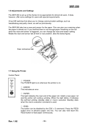
It has DIP switches that there is not enough paper remaining on . ○ ERROR This indicates an error. ○ PAPER This light indicates the near end of the paper roll. The SRP-350 also has a near -end sensor setting. Install a new paper roll and the printer will continue printing. If you ...find that allow you to be disabled by the ESC c 5 command. SRP-350 1-6 Adjustments and Settings The SRP-350 is set up at front or rear ...
It has DIP switches that there is not enough paper remaining on . ○ ERROR This indicates an error. ○ PAPER This light indicates the near end of the paper roll. The SRP-350 also has a near -end sensor setting. Install a new paper roll and the printer will continue printing. If you ...find that allow you to be disabled by the ESC c 5 command. SRP-350 1-6 Adjustments and Settings The SRP-350 is set up at front or rear ...

User Manual
Page 18
...The PAPER LED light blinks). The self-test begins. 2-3 The self-test prints the current printer status, which provides the control ROM version and the DIP switch setting. 2-4 After printing the current printer status, self-test printing will print the following ; 2-1 Make sure paper roll has been ...the FEED button. Self-test printing. The printer prints a pattern using the built-in character set. 2-6 The self-test automatically ends and cuts the paper after printing the following. *** COMPLETED *** 2-7 The printer is ready to continue printing. SRP-350 2. Please press the FEED button 2-5 ...
...The PAPER LED light blinks). The self-test begins. 2-3 The self-test prints the current printer status, which provides the control ROM version and the DIP switch setting. 2-4 After printing the current printer status, self-test printing will print the following ; 2-1 Make sure paper roll has been ...the FEED button. Self-test printing. The printer prints a pattern using the built-in character set. 2-6 The self-test automatically ends and cuts the paper after printing the following. *** COMPLETED *** 2-7 The printer is ready to continue printing. SRP-350 2. Please press the FEED button 2-5 ...


